1900 MITSUBISHI DIAMANTE brake rotor
[x] Cancel search: brake rotorPage 10 of 408
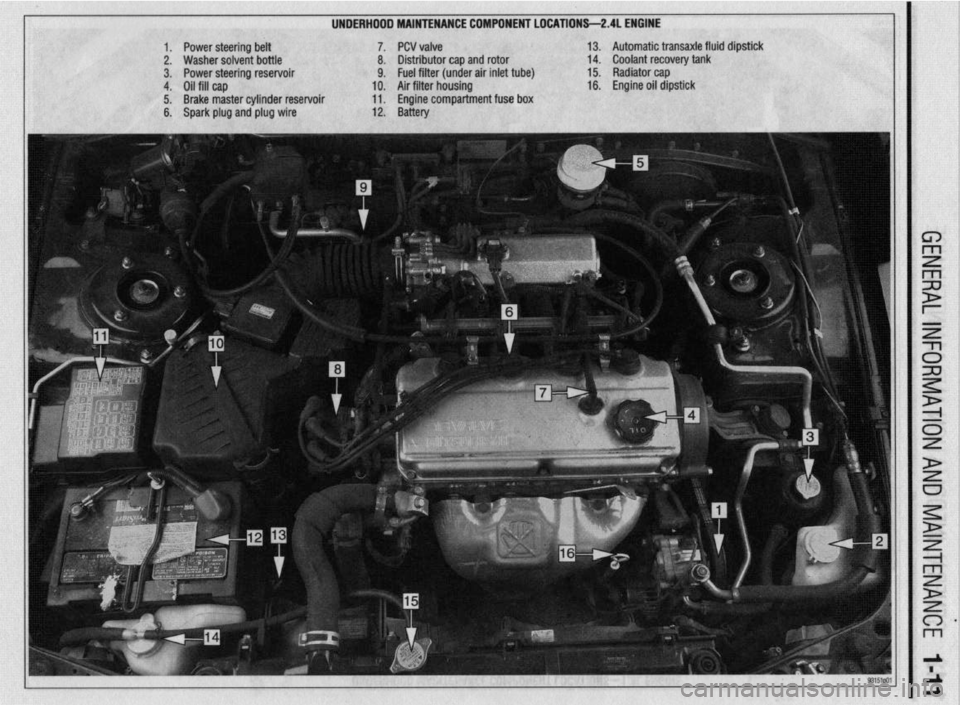
UNDERHDDD MAINTENANCE COMPONENT LOCATIONS-2AL ENGINE
II
1. Power steering belt 7. PCV valve
2. Washer solvent bottle 8. Distributor cap and rotor
3. Power steering reservoir 9. Fuel filter (under air inlet tube)
4. Oil fill cap 10. Air filter housing
5. Brake master cylinder reservoir 11. Engine compartment fuse box
6. Spark plug and plug wire 12. Battery 13. Automatic transaxle fluid dipstick
14. Coolant recovery tank
15. Radiator cap
16. Engine oil dipstick
Page 294 of 408
DRIVETRAiN 7-15
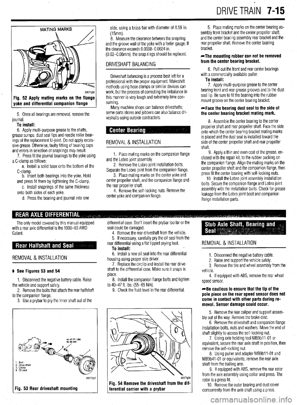
MATING MARKS
/
89577Q5E Fig. 52 Apply mating marks on the flange
yoke and differential companion flange
5. Once all bearings are removed, remove the
journal.
To install:
6. Apply multi-purpose grease to the shafts,
grease sumps, dust seal lips and needle roller bear-
ings of the replacement U-joint Do not apply exces-
sive grease Otherwse, faulty fitting of bearing caps
and errors in selection of snaprings may result.
7. Press fit the journal bearings to the yoke using
a C-clamp as follows:
a. Install a solid base onto the bottom of the
C-clamp.
b. Insert both bearings into the yoke. Hold
and press fit them by tightening the C-clamp.
c. Install snaprings of the same thickness
onto both sides of each yoke.
d. Press the bearing and journal into one side, using a brass bar with diameter of 0.59 in.
(15mm).
8. Measure the clearance between the snapring
and the groove wall of the yoke with a feeler gauge. If
the clearance exceeds 0.0008-0.0024 in.
(0.02-O.O6mm), the snap rings should be replaced.
DRIVESHAFT BALANCING
Driveshaft balancing is a process best left for a
professional wrth the proper equipment. Makeshift
methods using hose clamps or similar devices can
work, but the process of correcting the imbalance in
this manner is very tough and extremely time con-
suming.
Many machine shops can balance driveshafts;
some parts stores and jobbers can also balance dri-
veshafts using outside contractors.
REMOVAL&INSTALLATION
1. Place matmg marks on the companron flange
and the Lobro joint assembly
2. Remove the Lobro joint installation bolts.
Separate the Lobro joint from the companion flange.
3. Place mating marks on the center yoke and
center propeller shaft, and the companion flange and
the rear propeller shaft.
4. Remove the self-locking nuts. Remove the
center yoke and companion flange. 5. Place mating marks on the center bearing as-
sembly front bracket and the center propeller shaft,
and the center bearing assembly rear bracket and the
rear propeller shaft. Remove the center bearing
bracket.
*The mounting rubber can not be removed
from the center bearing bracket.
6. Pull out the front and rear center bearings
with a commercially available puller
To install:
7. Apply multi-purpose grease to the center
bearing front and rear grease grooves and to the dust
seal lip Be sure to fit the bearing into the rubber
mount groove on the center bearing bracket.
*Face the bearing dust seal to the side of
the center bearing bracket mating mark.
8. Assemble the center bearing to the center
propeller shaft and rear propeller shaft. Face the side
onto which the center bearing bracket mating marks
IS placed and the dust seal is installed toward the
side of the center propeller shaft and rear propeller
shaft.
9 Apply a thin and even coat of the grease, en-
closed with the repair kit, to the rubber packing on
the companion flange. Align the mating marks on the
center propeller shaft and the companion flange, then
press fit the center bearing with self-locking nuts.
10 Install the Lobro joint assembly installation
bolts. Secure the companron flange and Lobro joint
assembly with the installation bolts Check for grease
leakage from the Lobro joint boot and companion
flange installabon parts.
The only model covered by this manual equipped
with a rear axle differential is the 1990-93 AWD
Galant.
REMOVAL &INSTALLATION
# See Figures 53 and 54
1. Disconnect the negative battery cable. Raise
the vehicle and support safely.
2. Remove the bolts that attach the rear halfshaft
to the comoanion flanae.
3. Use’a prybar topry the inner shaft out of the
I Fig. 53 Rear driveshaft mounting
89577g5
differential case. Don’t insert the prybar too far or the
seal could be damaged.
4 Remove the rear driveshaft from the vehicle.
5. If necessary, carefully pry the oil seal from the
rear differential using a flat tipped prying tool.
To install:
6. Install a new oil seal into the rear differential
housing using proper size driver.
7. Replace the circlip and install the rear drive-
shaft to the differential case. Make sure it snaps in
place.
8. Install the companion flange bolts and tighten
to 40-47 ft. Ibs. (55-65 Nm).
9. Check the fluid level in the rear differential.
69577958 Fig. 54 Remove the driveshaft from the dif-
ferential carrier with a prybar
REMOVAL &INSTALLATION
1. Disconnect the negative battery cable.
2. Raise and support the vehicle safely.
3 Remove the tire and wheel assembly from the
vehicle.
4 If equipped with ABS, remove the rear wheel
speed sensor.
*Be cautious to ensure that the tip of the
pole piece on the rear speed sensor does not
come in contact with other parts during re-
moval. Sensor damage could occur.
5. Remove the rear caliper and support assem-
bly out of the way. Remove the brake disc.
6. Remove the driveshaft and companion flange
installation bolts, nuts and washers. Move the end of
shaft slightly to access the self-locking nut.
7. Using axle holding tool MBSbll-01 or
equivalent, secure the rear axle shaft in position, then
remove the self-locking nut.
8. Using puller and adapter MBSbll-01 and
MB9b41-01 or equivalents, remove the rear axle
shaft from the trailing arm
9. If equipped with ABS, remove the rear rotor
from the axle assembly using collar and press. The
rotor is a press fit.
10 Remove the outer bearing and dust cover
concurrently from the axle shaft using a press.
Page 295 of 408
.
7-16 DRIVETRAIN
11. Using puller, remove the oil seal and inner 18. While holding the rear axle shaft in positron
bearing from the trailing arm. using holding fixture tool MB9g67-01 or equivalent,
12. Inspect the companion flange and axle shaft tighten a new self-locking nut to 159 ft. Ibs. (220 Nm).
for wear or damage. Inspect the dust cover for defor- 19. Install the drive shaft nuts, washers and bolts.
mation or damage. Inspect the bearings for burning Tighten to 40-47 ft. Ibs. (55-65 Nm).
or declaration. Replace components as required 20. Install the rear brake disc, caliper assembly
To install: and parking brake.
13. Using the proper driver, press fit the inner
bearing onto the trailing arm. Press fit the oil seal
onto the trailing arm with the depression in the oil
seal facing upward, and until it contacts the shoulder
on the inner arm. 21. Install the tire and wheel assembly and lower
the vehrcle. Check the parking brake stroke and ad-
just as required.
22. Before moving the vehicle, pump the brakes
until a firm pedal is achieved.
*When tapping the oil seal in, use a plastic
hammer to lightly tap the top and circumfer-
ence of the seal installation tool, press fitting
gradually and evenly.
14. Press fit the dust covers onto the axle until it
contacts the axle shaft shoulder. Install the innermost
cover so the deDression is facino
UDWard.
REMOVAL &INSTALLATION
1. Raise the vehicle and support safely.
2. Matchmark the driveshaft and comoanion . ,
*When tapping the oil seal in, use a plastic
hammer to lightly tap the top and circumfer-
ence of the seal installation tool, press fitting
gradually and evenly. flange and remove the shaft. Don’t let it hang from the
transaxle. Tie It up to the underbody.
3. Hold the companion flange stationary and re-
move the large self-locking nut in the center of the
comoanion flanoe.
15. Apply multi-purpose grease around the entire 4: Using a Gller, remove the flange. Pry the old
circumference of the Inner side of the outer bearing seal out.
seal lip. Press fit the outer bearing to the axle shaft so
To install: that the bearrng seal lip surface is facing towards the 5. Apply a thin coat of multi-purpose grease to the
axle shaft flange. seal lip and the companion flange seal contacting sur-
16. Press fit the rear rotor to the axle shaft with face. Install the new seal with an appropriate driver.
the rear rotor groove surface towards the axle shaft 6. Install the companion flange. Install a new lock-
flange. nut and torque to 116-159 fl Ibs. (157-220 Nm). The
17. Install the rear axle shaft to the trailing arm rotation torque of the drive pinion should be about 4
temporarily. Install the companion flange to the rear inch Ibs. for new or reused, oiled bearings
axle shaft, then install a new self-locking nut. 7. Install the driveshaft.
REMOVAL &INSTALLATION
1. Raise the vehicle and support safely.
2. Drain the differential gear oil and remove the
center exhaust pipe.
3. Matchmark and remove the rear driveshaft.
4. Remove the rear halfshafts.
5. Remove the center exhaust pipe and muffler
assembly, as required.
6. Remove or disconnect the 4 wheel steering
oil pump.
7. The large mounting bolts that hold the differ-
ential carrier support plate to the underbody may use
self-locking nuts. Before removing them, support the
rear axle assembly in the middle with a transaxle
jack. Remove the nuts, then remove the support
plate(s) and the square dynamic damper from the rear
of the carrier.
8 Lower the differential carrier and remove from
the vehicle.
To install: 9. Raise the rear differential carrier into position
and install support member bolts. Install new lock-
nuts on all support bolts.
10. Install the 4 wheel steering oil pump.
11. Install new circlips on both rear driveshafts
and install.
12. Install the propeller shaft.
13. Install the center exhaust pipe and muffler.
14. Lower the vehicle.
15. With the vehicle level, fill the rear differential.
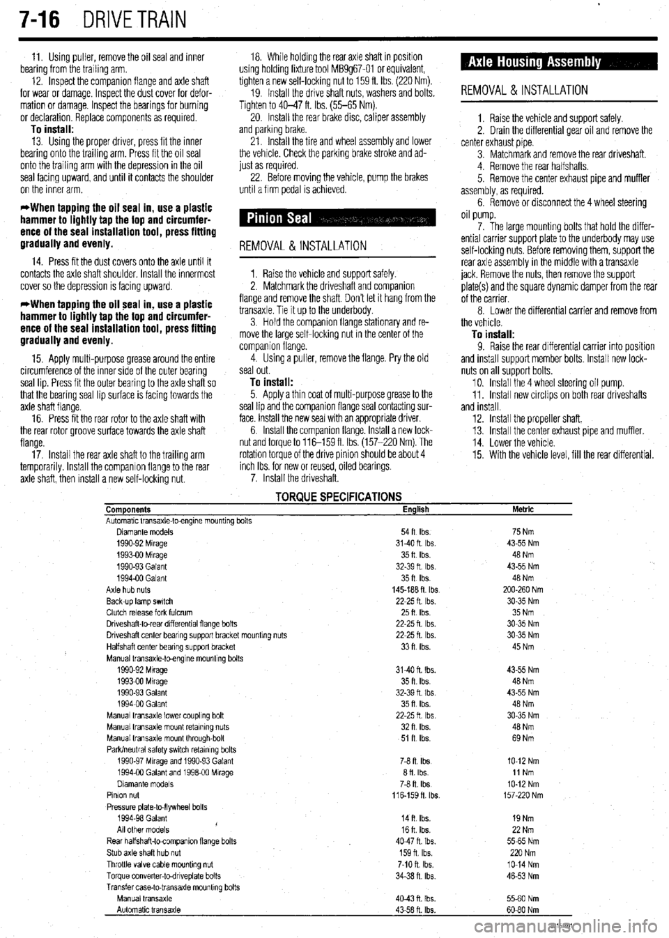
TORQUE SPECIFICATIONS Components English
Automatic Vansaxle-toengme mountrng bolts
Diamante models 54ft Ibs.
1990-92 Mrrage 3140ft Ibs.
199390 Mrrage 35ft Ibs.
1990-93 Galant 32-39 ft Ibs.
199400 Galant 35ft Ibs.
Axle hub nuts 145-188 ft tbs
Back-up lamp swatch 22-25 ft Ibs.
Clutch release fork fulcrum 25ft Ibs
Driveshaft-to-rear drfferentral flange bolts 22-25 fl lb?..
Driveshaft center bearrng support bracket mountrng nuts 22-25 fl. Ibs.
Halfshaft center bearing support bracket 33ft Ibs.
Manual transaxle-toengrne mountrng bolts
1990-92 Mtrage 3140 ft. Ibs.
1993-00 Mrrage 35 ft. Ibs.
1990-93 Galant 32-39 fl I bs.
199400 Galant 35ft Ibs.
Manual transaxle lower coupling bolt 22-25ft Ibs
Manual transaxle mount retaining nuts 32ft Ibs.
Manual transaxle mount through-bolt 51 R Ibs.
Park/neutral safety swatch retainrng bolts
1990-97 Mrrage and 1990-93 Galant 76 ft. Ibs
1994-00 Galant and 199600 Mirage afl Ibs
Dramante models
78 fl. Ibs
Pinion nut
116-159fl lb?..
Pressure plate-to-flywheel bolts
1994-98 Galant
14ft Ibs.
/
All other models 16ft Ibs.
Rear halfshaft-tocompanron flange bolts 4047ft Ibs.
Stub axle shaft hub nut 159n Ibs.
Throttle valve cable mounting nut 7-10 ft. Ibs.
Torque converter-todnveplate bolts 34-38 n. ibs
Transfer case-to-transaxle mounttng bolts
Manual transaxle
4043n Ibs.
Automatic transaxle
43-58 ft. Ibs. Metric
75 Nm
43-55 Nm
48 Nm
43-55 Nm
48 Nm
200-260 Nm
30-35 Nm
35 Nm
30-35 Nm
30-35 Nm
45 Nm
43-55 Nm
48 Nm
43-55 Nm
48 Nm
30-35 Nm
40 Nm
69 Nm
IO-12 Nm
11 Nm
IO-12 Nm
157-220 Nm
19 Nm
22 Nm
5565 Nm
220 Nm
lo-14 Nm
46-53 Nm
5560 Nm
60-80 Nm
93157co1
Page 297 of 408
.
8-2 SUSPENSION AND STEERING
b
REMOVAL &INSTALLATION
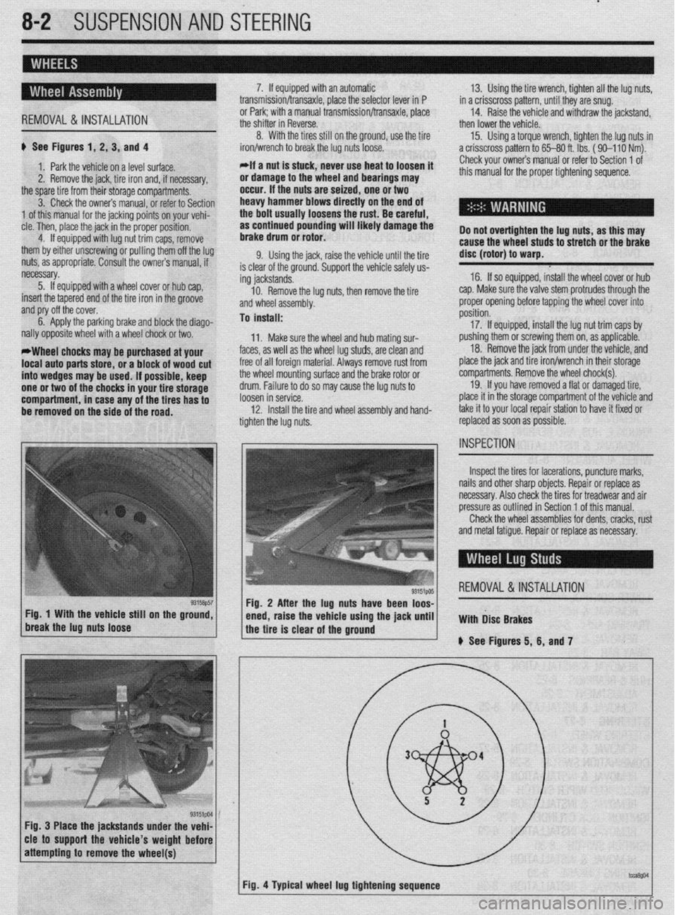
# See Figures 1, 2, 3, and 4
1. Park the vehicle on a level surface.
2. Remove the jack, tire iron and, if necessary,
the spare tire from their storage compartments.
3. Check the owners manual, or refer to Section
1 of this manual for the jacking points on your vehi-
cle. Then, place the jack in the proper position,
4. If equipped with lug nut trim caps, remove
them by either unscrewing or pulling them off the lug
nuts, as appropriate. Consult the owners manual, if
necessary.
5. If equipped with a wheel cover or hub cap,
insert the tapered end of the tire iron in the groove
and pry off the cover.
6. Apply the parking brake and block the diago-
nally opposite wheel with a wheel chock or two.
*Wheel chocks may be purchased at your
local auto parts store, or a block of wood cut
into wedges may be used. If possible, keep
one or two of the chocks in your tire storage
compartment, in case any of the tires has to
be removed on the side of the road. 7. If equipped with an automatic
transmission/transaxle, place the selector lever in P
or Park; with a manual transmission/transaxle, place
the shifter in Reverse.
8. With the tires still on the ground, use the tire
iron/wrench to break the lug nuts loose.
*If a nut is stuck, never use heat to loosen it
or damage to the wheel and bearings may
occur. If the nuts are seized, one or two
heavy hammer blows directly on the end of
the bolt usually loosens the rust. Be careful,
as continued pounding will likely damage the
brake drum or rotor.
9. Using the jack, raise the vehicle until the tire
is clear of the ground. Support the vehicle safely us-
ing jackstands.
10. Remove the lug nuts, then remove the tire
and wheel assembly.
To install:
11. Make sure the wheel and hub mating sur-
faces, as well as the wheel lug studs, are clean and
free of all foreign material. Always remove rust from
the wheel mounting surface and the brake rotor or
drum. Failure to do so may cause the lug nuts to
loosen in service.
12. Install the tire and wheel assembly and hand-
tighten the lug nuts. 13. Using the tire wrench, tighten all the lug nuts,
in a crisscross pattern, until they are snug.
14. Raise the vehicle and withdraw the jackstand,
then lower the vehicle.
15. Using a torque wrench, tighten the lug nuts in
a crisscross pattern to 65-80 ft. lbs. ( 90-l 10 Nm).
Check your owners manual or refer to Section 1 of
this manual for the proper tightening sequence.
Do not overtighten the lug nuts, as this may
cause the wheel studs to stretch or the brake
disc (rotor) to warp.
16. If so equipped, install the wheel cover or hub
cap. Make sure the valve stem protrudes through the
proper opening before tapping the wheel cover into
position.
17. If equipped, install the lug nut trim caps by
pushing them or screwing them on, as applicable.
18. Remove the jack from under the vehicle, and
place the jack and tire iron/wrench in their storage
compartments. Remove the wheel chock(s).
19. If you have removed a flat or damaged tire,
place it in the storage compartment of the vehicle and
take it to your local repair station to have it fixed or
replaced as soon as possible.
Inspect the tires for lacerations, puncture marks,
nails and other sharp objects. Repair or replace as
necessary. Also check the tires for treadwear and air
pressure as outlined in Section 1 of this manual.
Check the wheel assemblies for dents, cracks, rust
and metal fatigue. Repair or replace as necessary.
REMOVAL&INSTALLATION
Fig. 3 Place the jackstands under the vehi-
cle to support the vehicle’s weight before
Page 298 of 408
SUSPENSION AND STEERiNG 8-3
STUD
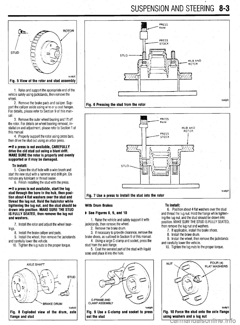
Fig. 5 View of the rotor and stud assembly
1. Raise and support the appropriate end of the
vehicle safely using jackstands, then remove the
wheel.
2. Remove the brake pads and caliper. Sup-
port the caliper aside using wire or a coat hanger.
For details, please refer to Section 9 of this man-
ual.
3 Remove the outer wheel bearing
and liff off
the rotor. For details on wheel bearing removal, in-
stallation and adjustment, please refer to Section 1 of
this manual.
4. Properly support the rotor using press bars,
then drive the stud out using an arbor press.
*If a press is not available, CAREFULLY
drive the old stud out using a blunt drift.
MAKE SURE the rotor is properly and evenly
supported or it may be damaged.
To install:
5. Clean the stud hole with a wire brush and
start the new stud with a hammer and drift pin. Do
not use any lubricant or thread sealer.
6. Finish installing the stud with the press.
*If a press is not available, start the lug
stud through the bore in the hub, then posi-
tion about 4 flat washers over the stud and
thread the lug nut. Hold the hub/rotor while
tightening the lug nut, and the stud should be
drawn into position. MAKE SURE THE STUD
IS FULLY SEATED, then remove the lug nut
and washers.
7. Install the rotor and adjust the wheel bear-
ings
8. Install the brake caliper and pads.
9. Install the wheel, then remove the jackstands
and carefully lower the vehicle.
10. Tighten the lug nuts to the proper torque.
AXLE SHAFT
Im3goa
3g. 8 Exploded view of the drum, axle
lange and stud
PRESS RAM
PRESS
STOCK
Fig. 6 Pressing the stud from the rotor
tcca$Oi Fig. 7 Use a press to install the stud into the rotor
With Drum Brakes To install:
6. Position about 4 flat washers over the stud p See Figures 8, 9, and 10
1. Raise the vehicle and safely support it with
jackstands, then remove the wheel.
2. Remove the brake drum.
3. If necessary to provide clearance, remove the
brake shoes, as outlined in Section 9 of this manual.
4. Using a large C-clamp and socket, press the
stud from the axle flange.
5. Coat the serrated part of the stud with liquid
soap and place it into the hole. and thread the lug nut. Hold the flange while tighten-
ing the lug nut, and the stud should be drawn into
position. MAKE SURE THE STUD IS FULLY SEATED,
then remove the lug nut and washers.
7. If applicable, install the brake shoes.
8. Install the brake drum.
9. Install the wheel. then remove the iackstands
and carefully lower the vehicle.
10. Tighten the lug nuts to the proper torque.
C-FRAME AND
CLAMP ASSEMBLY
Fig. 9 Use a C-clamp and socket to press
out the stud
NUT FLAT WASHERS
Fig. 10 Force the stud onto the axle flange
using washers and a lug nut
Page 310 of 408
SUSPENSION AND STEERING 845
144-188 ft. Ibs. (200-260 Nm). Rotate the hub ing knuckle and install a new nut. Tighten to 52 ft. 3. Remove the cotter pin, halfshaft nut and
to seat the bearing.
Ibs. (72 Nm). washer.
e. Mount the knuckle assembly in a vise.
12. Install the halfshaft into the hub/knuckle as- 4. If equipped with ABS, remove the Vehicle
Check the hub assembly turning torque and end- sembly.
Speed Sensor (VSS).
play as follows: 13. Install the two front strut lower mounting bolts
5. Remove the caliper and brake pads. Support
l Using a torque wrench and socket
and tighten to 80-94 ft. Ibs. (110-130 Nm) on Mirage
the caliper out of the way using wire.
MB990998 or equivalent, turn the hub in the or 65-76 ft. Ibs. (90-105 Nm) on Diamante models. 6. Remove the brake rotor from the hub assembly.
knuckle assembly. Note the reading on the torque
14. Install the tie rod end and tighten the nut to 7. Disconnect the upper ball joint from the
wrench and compare to the desired reading of 16
25 ft. lbs. (34 Nm) for Mirage and 21 ft. Ibs. (29 Nm) steering knuckle and pull the knuckle outward.
inch Ibs. (1.8 Nm) or less. This is known as the ‘on Diamante models
8. From the back of the knuckle, remove the
breakaway torque.
15. Install the brake disc and caliper assembly. ‘four bolts securing the hub to the knuckle.
l Check for roughness when turning the
16. If equipped with Active-ECS, connect the
9. Remove the hub and bearing assembly from
bearing.
height sensor and tighten the mounting bolt to 15 ft.
the knuckle.
0 Mount a dial indicator on the hub so the
Ibs. (20 Nm).
pointer contacts the machined surface on the hub.
17. Install the front speed sensor, if removed.
*The hub assembly is not serviceable and
l Check the end-play.
18. Install the washer and new locknut to the end should not be disassembled.
l Compare the reading to the limit of 0.002
in. (0.05mm). of the halfshaft. Tighten the locknut snugly to To install: 144-188 ft. Ibs. (200-260 Nm).
f. If the starting torque or the hub end-play
19. Install the tire and wheel assembly onto the 10. Install the hub to the steering knuckle and
are not within specifications while the nut is tighten the mounting bolts to 65 ft. Ibs. (88 Nm).
vehicle.
11.
tightened to 144-188 ft. Ibs. (200-260 Nm), the
Lower the vehicle to the ground. Connect the upper ball joint to the steering
20.
bearing, hub or knuckle have probably not been ‘knuckle and tighten the self-locking nut to 21 ft. Ibs.
(28 Nm).
installed correctly. Repeat the disassembly and 1994-98 Galant 12.
‘assembly procedure and recheck starting torque Install the axle washer and nut. Tighten the
and end-play. nut to 145-188 ft. Ibs. (200-260 Nm).
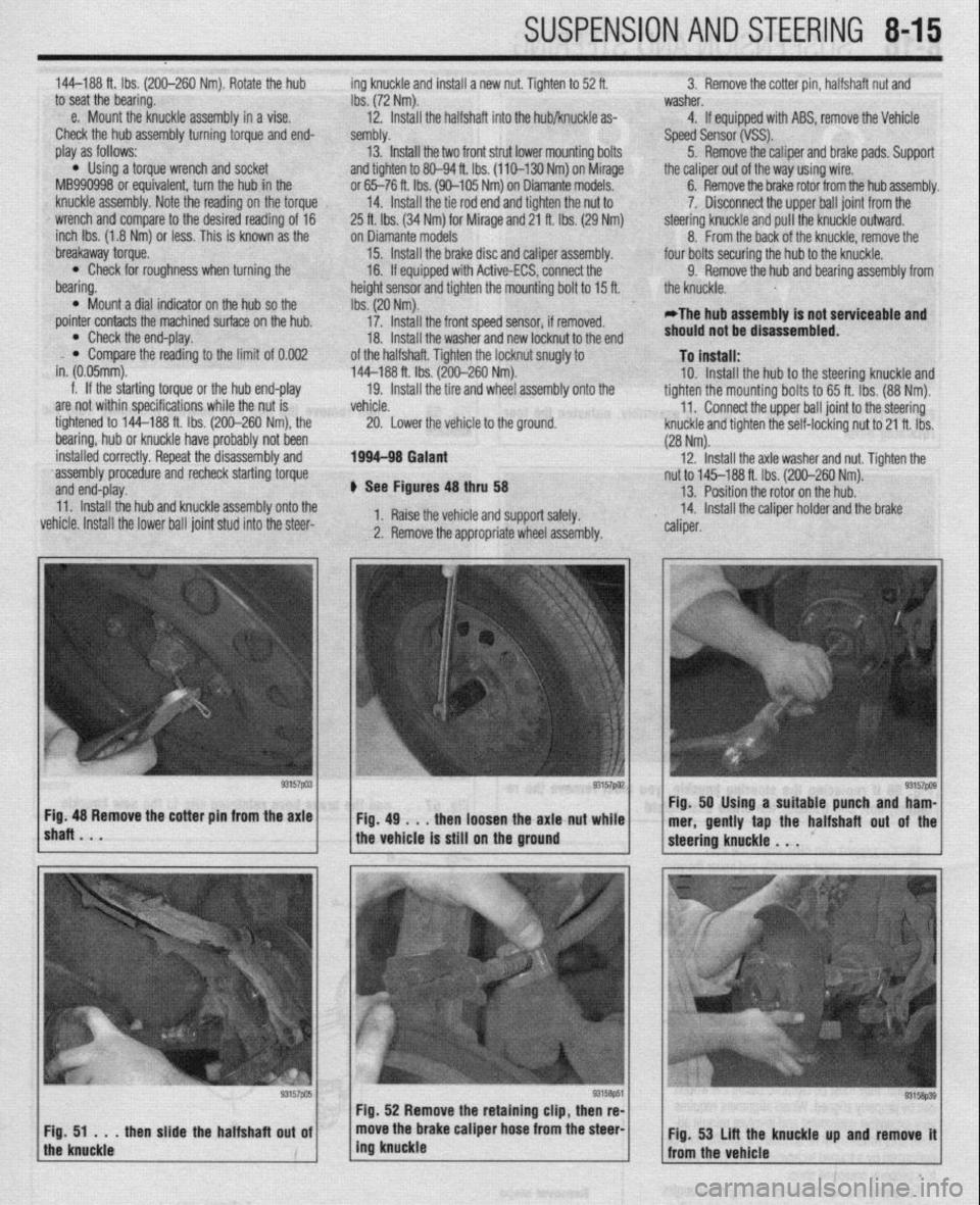
+ See Figures 48 thru 58 13. Position the rotor on the hub.
11. Install the hub and knuckle assembly onto the
vehicle. Install the lower ball joint stud into the steer- 1. Raise the vehicle and support safely. 14. Install the caliper holder and the brake
2. Remove the appropriate wheel assembly. ” caliper.
lshaRBmV * “57pa3~ ~Fig.4g~..thenloosehtheaxlattut~~;.~ Fig. 48 Remove the cotter pm from the axle Fig. 50 Using a suitable punch and ham-
mer, gently tap the halfshaft out of the
the vehicle is still on the ground
Page 319 of 408
8-24 SUSPENSION AND STEERING
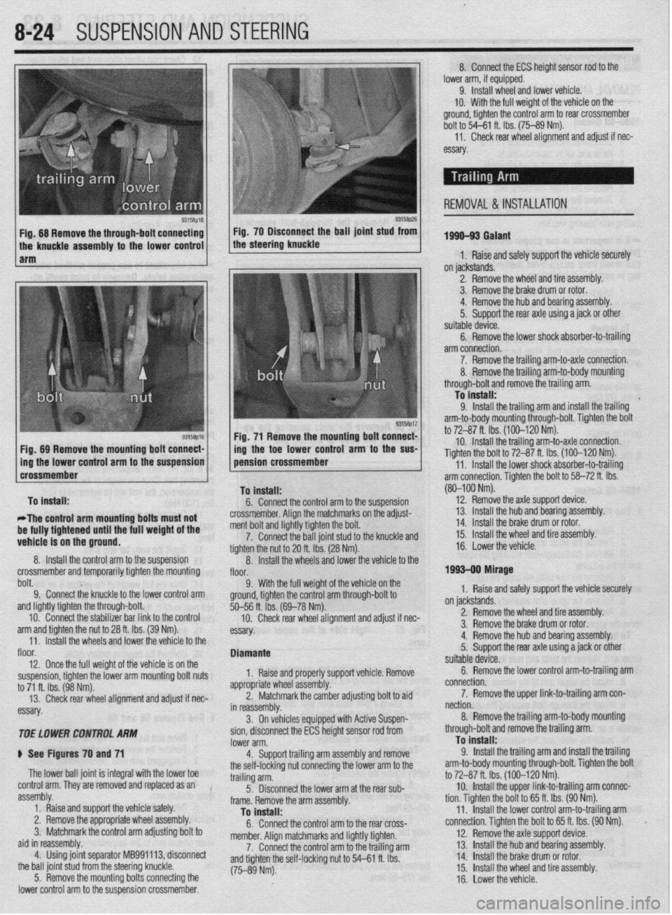
9315t$M 93158p26 Fig. 68 Remove the through-bolt connecting Fig. 70 Disconnect the ball joint stud from
the knuckle assembly to the lower control the steering knuckle
1 arm
Fig. 71 Remove the mounting bolt connect-
Fig, 89 Remove the mounting bolt connect- /
1 ing the toe lower control arm to the SW
Dolt. 9; Connect the knuckle to the lower control arm 9. With the full weigh
ground, tighten the control
and lightly tighten the through-bolt.
10. Connect the stabilizer bar link to the control
arm and tighten the nut to 28 ft. Ibs. (39 Nm).
11. Install the wheels and lower the vehicle to the
floor.
12. Once the full weight of the vehicle is on the
suspension, tighten the lower arm mounting bolt nuts
to 71 ft. Ibs. (98 Nm).
13. Check rear wheel alignment and adjust if nec-
essary.
TOE LOWER CONTROL ARhl
ti See Figures 70 and 71
The lower ball joint is integral with the lower toe
control arm. They are removed and replaced as an
assembly.
1. Raise and support the vehicle safely.
2. Remove the appropriate wheel assembly.
3. Matchmark the control arm adjusting bolt to
aid in reassembly.
4. Using joint separator MB991113, disconnect
the ball joint stud from the steering knuckle.
5. Remove the mounting bolts connecting the
lower control arm to the suspension crossmember. %--56 ft. ibs. (
10. Check
essay. rem an0 aajusr
II nec-
orl vehicle Remove
ldiustina bolt to aid
soen- Diamante
1, Raise and properly supp
appropriate whl
eel assembly.
2. Matchn
narkthe camber a , _
in reassembly.
3. On vehicles equipped with Active Su r
sion, disconnect the ECS height sensor rod from
lower arm.
4. Support trailing arm assembly and remove
the self-locking nut connecting the lower arm to the
trailing arm.
5. Disconnect the lower arm at the rear sub-
frame. Remove the arm assembly.
To install:
6. Connect the control arm to the rear cross-
member. Alion matchmarks and liahtlv tiohten.
7. Connect the control arm tothe trailing arm
and tighten the self-locking nut to 54-P e rho I I IL IY.J.
(75-89 Nm). 8. Connect the ECS height sensor rod to the
lower arm, if equipped.
9. Install wheel and lower vehicle.
IO. With the full weight of the vehicle on the
ground, tighten the control arm to rear crossmember
bolt to 54-61 ft. Ibs. (75-89 Nm).
11,
Check rear wheel alignment and adjust if nec-
essary
1996-93 Galant
1, Raise and safely support the vehicle securely
on jackstands.
2. Remove the wheel and tire assembly.
3. Remove the brake drum or rotor.
4. Remove the hub and bearing assembly.
5.
Support the rear axle using a jack or other
suitable device.
6. Remove the lower shock absorber-to-trailing
arm connection.
7. Remove the trailing arm-to-axle connection.
REMOVAL & INSTALLATION
(80-100 Nm).
12.
Remove the axle suooort device.
on jackstands.
2. Remove the wheel and tire assembly.
3. Remove the brake drum or rotor.
4. Remove the hub and bearing assembly.
5.
Support the rear axle using a jack or other
suitable device.
6. Remove the lower control arm-to-trailing arm
connection.
7. Remove the upper link-to-trailing arm con-
nection.
8. Remove the trailing arm-to-body mounting
through-bolt and remove the trailing arm.
To install:
9.
Install the trailing arm and install the trailing
arm-to-body mounting through-bolt. Tighten the bolt
to 72-87 ft. Ibs. (100-120 Nm).
10. Install the upper link-to-trailing arm connec-
tion. Tighten the bolt to 65 ft. Ibs. (90 Nm).
11. Install the lower control arm-to-trailing arm
connection. Tighten the bolt to 65 ft. Ibs. (90 Nm).
12. Remove the axle support device.
13. Install 1 he hub and bearing assembly.
14 Install 1
. _ .he brake drum or rotor.
15.
Install the wheel and tire assembly.
16. Lower the vehicle.
Page 320 of 408
SUSPENSION AND STEERING 8-25
1994-00 Galant and 1997-00 Diamante
4. Remove the retainer bolts and the stabilizer
..- 8, Loosely in”,“,, +I?,, r+&,il;7nr kn- h.~r.l,,d” -..
1. Raise and safely support the vehicle securely he bushing.
the vehicle.
on jackstands.
7er hnr with FI wmnph Remnun (1 Alinn th
2. Remove the wheel and tire assembly.
3. Support the rear axle using a jack or other
suitable device.
4. Remove the trailing arm-to-knuckle connec-
tion,
5. Remove the trailing arm-to-body mounting
n~~““yll-““!~ (1II” fWll”“C LllG llcllllll$j a,,,,. To install:
6. Install the trailing arm and install the trailing
arm-to-body mounting through-bolt. Tighten the bolt
to 99-114 ft. Ibs. (137-157 Nm).
7. Install the trailing arm-to-knuckle connection. Dar brackets. Hemove t
5. Hold the stabilL_. __. . . _ . .._..“... ..I . .._._
the self-locking nut.
6. Once the stabilizer bar nut is removed, re-
move the joint cups and stabilizer rubber bushing.
7. Hold the stabilizer link with a wrench and re-
move the self-locking nuts. Remove the stabilizer
link.
8. Lower the jack supporting the rear axle
in a slight gap between the rear sus-
? body of the vehicle.
! the stabilizer bar.
IL_ L__ I__ _)----- .-- .-J JAI.... slightly. Mainta
pension and thf
9. Remow
10. Inspect LIIB uar 101 uamage, wear ana aereno-
ration and replace as required.
-Fe c--a-...
1 IIIJMII UK 3La”III‘w “ill “lduKm “II
“. , ,,LY,, ,,ie side locating markings on the stabi-
lizer bar, so that the marking on the bar extends ap-
proximately 0.39 inches (1Omm) from the outer edge
of the mounting bracket, on both sides.
10. With the stabilizer bar properly aligned,
tighten the mounting bracket bolts to 28 ft. Ibs. (39
Nm).
11. Connect the stabilizer links to the damper fork
andihe stabilizer bar. Tighten the locking nuts to 28
ft. Ibs. (38 Nm).
12. Lower the vehicle and connect the negative
8.. Ia
mery came.
Tighten the bolt to 85-99 ft. Ibs. (118-137 Nm).
nemove me axle suppon
9. Install the wheel and tire
10. Lower the vehicle. aewce.
assembly.
I 0 Insran: 11, Install the stabilizer bar into the vehicle. Raise
the rear axle and suspension into place.
12. Install the stabilizer link into the stabilizer ba
Ir
ADJUSTMENT anfi indc4ll 33 ft. Ibs. (45 Nm).
13. Install the ioint __-_ _.._ __
1. Raise and safely support the vehicle securely the link. Ins’
..I.,
Mlhiln hnlrii, tall a rkW self~locking n
lll~llG llUlulng the stabi” ” ’ ’ ’
wrench, tighten the self,
of the stabilizer link is v
ihe hub and bearing assembly.
5. Support the rear axle using a jack or other
suitable device.
6. Remove the lower shock absorber-to-trailing
arm connection. ocking nut. Tighten the nut to
ClrnC 2nd ?$bilizer rubber to
ut onto the link.
nzer nnK oall studs with a
-locking nut so the protrusion
within 0.354-0.433 in.
I stabilizer bar bushings,
>+nn thn hnk In -I A u (9-llmm).
14. Install the cente
brackets and bolts. Tiqt Mirage
*Never disassemble the rear hub bearing.
The wheel bearing is serviced by replace-
ment of the hub.
1. Raise and safely support the vehicle.
2. Remove the rear wheel.
3. Remove the caliper and brake disc of brake 1992-96 biamante
on IacKsranos.
2. Remove the wheel and tire assembly
3, Remove thn hralm rntnr 4. Remove1
7. Remove the stabilizer bar link-to-trailing arm
connection.
8. Remove the tie rod end-to-trailing arm con-
nection.
9. Remove the lower control arm-to-trailing arm
connection.
10. Remove the trailing arm-to-body mounting
through-bolt and remove the trailing arm. Nm).
15. Install the parking
sensor installation bolt.
, , I oraxe cat * ale ar
member bracket and tighten
i Nm). Tighten the crossmem-
A to 94 ft. Ibs. (130 Nm). 16. Install the cross
the bolt to 61 ft. Ibs. (8!
ber bracket mounting nl
17. Install the rubbe
locking nuts onto the cro:
the nuts to 80-94 fl. Ibs. (
18. Lower the vehicle. id rear speed drum.
4. Remove the dust cab and tighten the flange ll”, *lb+ to 130 ft. Ibs. (180 Nm).
5. Using a dial indicator, measure wheel bear-
!r insulators and new seif-
ismemoer ’ brackets. Tighten
[110-130 Nm). ing end-play. The maximum limit for end-play is
o.oc-- ‘^ -- rzu mcnes (u.usmm).
arol
tanc
sisk 6. Using a spring scale and a rope wrapped
md the bolts, measure the rotary sliding resis-
e of the bearing/hub. The maximum limit for re-
mce is 4 Ibs. (19 N).
7. If any of the readings exceed the specifica-
To install:
11. Install the trailing arm and install the trailina Diamante and 1994-98 Gal&i
t tions, replacement of the hub is required.
8. Install the dust cap.
9. Install the brake disc and caliper, or brake
negative battery ( sble.
;“I,-.
I support the vbhlblG.
stabilizer links by removing
Alizer bar mounting brackets
from the vehicle.
lonents for wear or damage,
ded. drum.
10. Install the rear wheel assembly and lower the
vehicle to the floor.
*
1990-93 Galant
*Vehicles equipped with rear disc brakes
use a sealed hub and bearing assembly,
which requires no adjustment. Drum brake
models are
adjusted using the following pro- arm-to-body mounting through-bolt. Tighten the bolt
to 101-116 ft. Ibs. (140-160 Nm). ) See Figure 72
12. Install the trailing arm-to-lower control arm
1. Disconnect the I
connection. Tighten the bolt to 101-116 ft. Ibs.
(140-160 Nm). 2. Raise and safely
13. Install the tie rod end-to-trailing arm connec- 3. Disconnect the I
tion. Tighten the nut to 21 ft. Ibs. (29 Nm). the self-locking nuts.
14. Install the stabilizer bar link-to-trailing arm 4. Remove the stat
connection. Tighten the nut to 29 ft. Ibs. (40 Nm). and bushings.
15. Install the lower shock absorber-to-trailing
5. Remove the bar
arm connection. Tighten the bolt to 65 ft. Ibs. (90 6. Inspect all comr
. and replace parts as nee
Nrn).
16. Remove the axle support device.
17. Install the hub and bkaring assembly,
18. Install the brake rotor.
19. Install the wheel and tire assembly.
20. Lower the vehicle.
REMOVALANDINSTALLATION
1990-93 Gaiant
1. Raise and support the vehicle safely.
2. Place a jack under the rear axle and suspen- To install:
7 InstA the dnhili cedure. ._._ . . .._ -.--.. lzer bar into the vehicle.
1. Raise the vehicle and support it safely.
2. Remove the wheel and tire assemblies.
3. If equipped with rear disc brakes, remove the
caliper assembly.
4. Remove the grease cap and the hub nut.
5. Tighten the wheel bearing nut to 20 ft. Ibs. (27
Nm) while rotatir ” ”
6. Back off th
load and then tighten it to 7 ft. Ibs. (10 Nm).
7. Install the nut lock and a new cotter pin.
8. If brake caliper was removed, reinstall.
9. Install the wheel and lower the vehicle.
Diamante and lQQ44 Galant 10 tne mum/hub.
ie adjusting nut to remove the pre-
Sian assembly.
3. Remove the self-locking nuts and crossmem-
ber bracket.
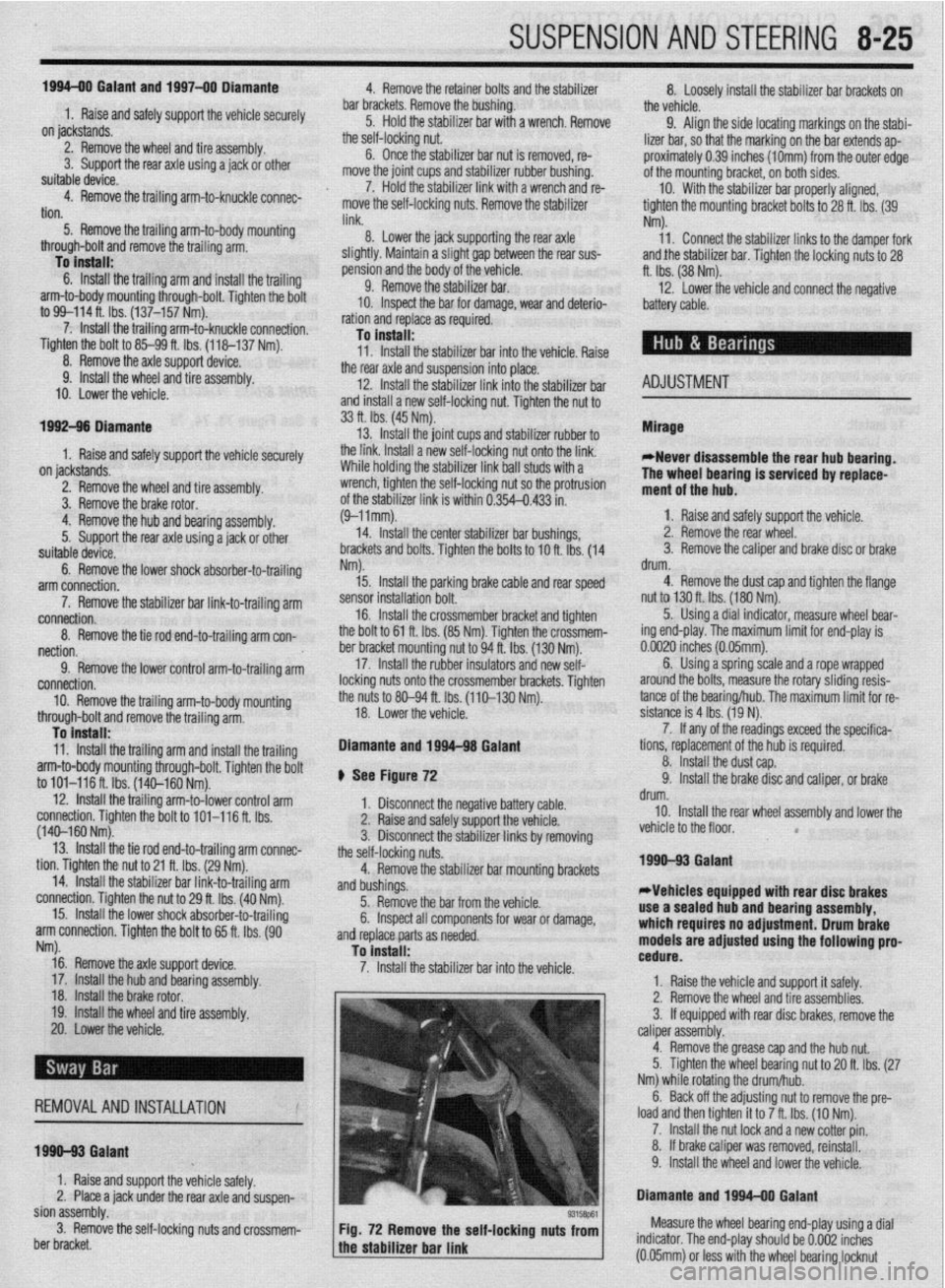
93158P61 Fig. 72 Remove the self-locking nuts from Measure the wheel bearing end-play using a dial
the stabilizer bar link indicator. The end-play should be 0.002 inches
a (0.05mm) or less with the wheel bearing locknut