1900 MITSUBISHI DIAMANTE brake rotor
[x] Cancel search: brake rotorPage 360 of 408
9-24 BRAKES
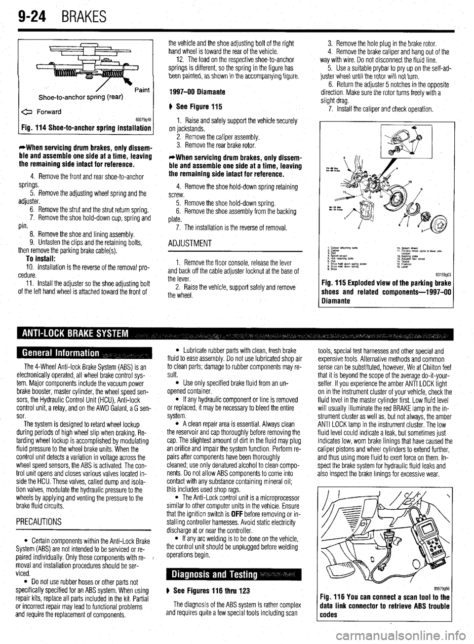
Shoe-to-anchor spring (rear)
e Forward
69579946 Fig. 114 Shoe-to-anchor spring installation
*When servicing drum
brakes, only dissem-
ble and assemble one side at a time, leaving
the remaining side intact for reference.
4. Remove the front and rear shoe-to-anchor
springs.
5. Remove the adjusting wheel spring and the
adjuster.
6. Remove the strut and the strut return spring.
7. Remove the shoe hold-down cup, spring and
pin.
8. Remove the shoe and lining assembly.
9. Unfasten the clips and the retaining bolts,
then remove the parking brake cable(s).
To install: 10. Installation is the reverse of the removal pro-
cedure.
11. Install the adjuster so the shoe adjusting bolt
of the left hand wheel is attached toward the front of the vehicle and the shoe adjusting bolt of the right
hand wheel is toward the rear of the vehicle. -
12. The load on the respective shoe-to-anchor
springs is different, so the spring in the figure has
hen painteb, a> shm in the a~~0mparrying figure.
1997-00 Diamante
‘) See Figure 115
1. Raise and safely support the vehicle securely
on jackstands.
2. Remove the caliper assembly.
3. Remove the rear brake rotor.
*When servicing drum brakes, only dissem-
ble and assemble one side at a time, leaving
the remaining side intact for reference.
4. Remove the shoe hold-down spring retaining
screw.
5. Remove the shoe hold-down spring.
6. Remove the shoe assembly from the backing
plate.
7. The installation is the reverse of removal.
ADJUSTMENT
1. Remove the floor console, release the lever
and back off the cable adjuster locknut at the base of
the lever.
2. Raise the vehicle, support safely and remove
the wheel. 3. Remove the hole plug in the brake rotor.
4. Remove the brake caliper and hang out of the
way with wire. Do not disconnect the fluid line.
5. Use a suitable prybar to pry up on the self-ad-
juskr V&I&I unti tie T&IT wi\ not tirn.
6. Return the adjuster 5 notches in the opposite
direction. Make sure the rotor turns freely with a
slight drag.
7. Install the caliper and check operation.
9. Shoe 93159go3 Fig. 115 Exploded view of the parking brake
shoes and related components-l 997-00
Diamante
The 4-Wheel Anti-lock Brake System (ABS) is an
electronically operated, all wheel brake control sys-
tem. Major components include the vacuum power
brake booster, master cylinder, the wheel speed sen-
sors, the Hydraulic Control Unit (HCU), Anti-lock
control unit, a relay, and on the AWD Galant, a G sen-
sor.
The system is designed to retard wheel lockup
during periods of high wheel slip when braking. Re-
tarding wheel lockup is accomplished by modulating
fluid pressure to the wheel brake units. When the
control unit detects a variation in voltage across the
wheel speed sensors, the ABS is activated. The con-
trol unit opens and closes various valves located in-
side the HCU. These valves, called dump and isola-
tion valves, modulate the hydraulic pressure to the
wheels by applying and venting the pressure to the
brake fluid circuits.
PRECAUTIONS
l Certain components within the Anti-Lock Brake
System (ABS) are not intended to be serviced or re-
paired individually. Only those components with re- !
moval and installation procedures should be ser-
viced.
0 Do not use rubber hoses or other parts not
specifically specified for an ABS system. When using
repair kits, replace all parts included in the kit. Partial
or incorrect repair may lead to functional problems
and require the replacement of components.
l Lubricate rubber parts with clean, fresh brake
fluid to ease assembly. Do not use lubricated shop air
to clean parts; damage to rubber components may re-
sult.
l Use only specified brake fluid from an un-
opened container.
l If any hydraulic component or line is removed
or replaced, it may be necessary to bleed the entire
system.
l A clean repair area is essential. Always clean
the reservoir and cap thoroughly before removing the
cap. The slightest amount of dirt in the fluid may plug
an orifice and impair the system function. Perform re-
pairs after components have been thoroughly
cleaned; use only denatured alcohol to clean compo-
nents. Do not allow ABS components to come into
contact with any substance containing mineral oil;
this includes used shop rags.
l The Anti-Lock control unit is a microprocessor
similar to other computer units in the vehicle. Ensure
that the ignition switch is
OFF before removing or in-
stalling controller harnesses. Avoid static electricity
discharge at or near the controller.
l If any arc welding is to be done on the vehicle,
the control unit should be unplugged before welding
operations begin.
) See Figures 116 thru 123
The diagnosis of the ABS system is rather complex
and requires quite a few special tools including scan tools, special test harnesses and other special and
expensive tools. Alternative methods and common
sense can be substituted, however, We at Chilton feel
that it is beyond the scope of the average do-it-your-
selfer. If you experience the amber ANTI LOCK light
on in the instrument cluster of your vehicle, check the
fluid level in the master cylinder first. Low fluid level
will usually illuminate the red BRAKE lamp in the in-
strument cluster as well as, but not always, the amber
ANTI LOCK lamp in the instrument cluster. The low
fluid level could indicate a leak, but sometimes just
indicates low, worn brake linings that have caused the
caliper pistons and wheel cylinders to extend further,
and thus using more fluid to exert force on them. In-
spect the brake system for hydraulic fluid leaks and
also inspect the brake linings for excessive wear.
89579956 Fig. 116 You can connect a scan tool to the
data link connector to retrieve ABS trouble
codes
Page 364 of 408
9-28 BRAKES
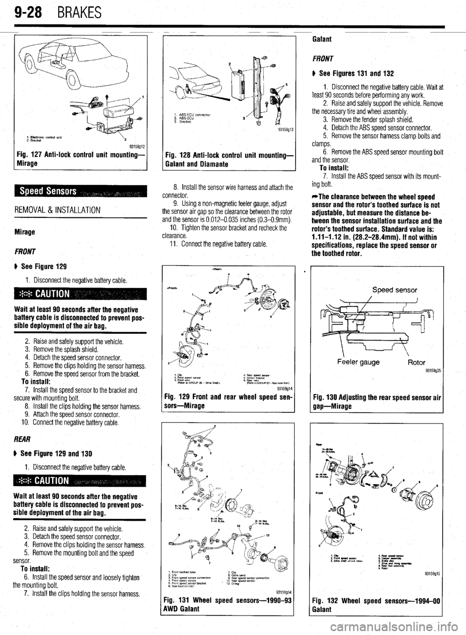
1. Electronic control una
2. Bracket 93159912 Fig. 127 Anti-lock control unit mounting-
Fig. 128 Anti-lock control unit mounting-
Mirage
Galant and Diamante
REMOVAL&INSTALLATION
Mirage
FRONT
I) See Figure 129
1, Disconnect the negative battery cable.
Wait at least 90 seconds after the negative
battery cable is disconnected to prevent pos-
sible deployment of the air bag.
2. Raise and safely support the vehicle.
3. Remove the splash shield.
4. Detach the speed sensor connector.
5. Remove the clips holding the sensor harness.
6. Remove the speed sensor from the bracket.
To install: 7. Install the speed sensor to the bracket and
secure with mounting bolt.
8. Install the clips holding the sensor harness.
9. Attach the speed sensor connector.
IO. Connect the negative battery cable.
REAR
8 See Figure 129 and 130
1. Disconnect the negative battery cable.
Wait at least 90 seconds after the negative
battery cable is disconnected to prevent pos-
sible deployment of the air bag.
2. Raise and safely support the vehicle.
3. Detach the speed sensor connector.
4. Remove the clips holding the sensor harness.
5. Remove the mounting bolt and the speed
sensor.
To install: 6. Install the speed sensor and loosely tighten
the mounting bolt,
7. Install the clips holding the sensor harness.
1. ABS-ECU ccr~nector
2. ABSECU
3. Bracket
8. Install the sensor wire harness and attach the
connector,
9. Using a non-magnetic feeler gauge, adjust
the sensor air gap so the clearance between the rotor
and the sensor is 0.012-0.035 inches (0.3-0.9mm).
IO. Tighten the sensor bracket and recheck the
clearance.
11. Connect the negative battery cable.
Fig. 129 Front and rear wheel speed sen-
sors-Mirage
1
3. Front speed sensor connwxwn
4 Fmnt sweed sensor
5 Front speed sensor bracket
6 Rear toothed rotor 8 Cabletand
8 Rear speed sensor connection
10 Rear speed sensx
12 omg
93159934 Fig. 131 Wheel speed sensors-1990-93
RWD Galant Galant
FRONT
# See Figures 131 and 132
1. Disconnect the negative battery cable. Wait at
least 90 seconds before performing any work.
2. Raise and safely support the vehicle. Remove
the necessary tire and wheel assembly.
3. Remove the fender splash shield.
4. Detach the ABS speed sensor connector.
5. Remove the sensor harness clamp bolts and
clamps.
6. Remove the ABS speed sensor mounting bolt
and the sensor.
To install: 7. Install the ABS speed sensor with its mount-
ing bolt.
*The clearance between the wheel speed
sensor and the rotor’s toothed surface is not
adjustable, but measure the distance be-
tween the sensor installation surface and the
rotor’s toothed surface. Standard value is:
1.11-1 .I2 in. (28.2-28.4mm). If not within
specifications, replace the speed sensor or
the toothed rotor.
Speed sensor
Feeler gauge
93159g35
Fig. 130 Adjusting the rear speed sensor air
gap-Mirage
6
Fig. 132 Wheel speed sensors-1994-00
Galant
Page 365 of 408
BRAKES 9-29
8. Reinstall the sensor harness with its clamps
and bolts.
9. Reconnect the speed sensor connector.
IO. Install the fender splash shield.
11. Reinstall the tire and wheel, safely lower the
vehicle, and reconnect the negative battery cable. To install: 7. Install the speed sensor and torque to 9 ft.
Ibs. (12 Nm).
8. Install the clips holding the sensor harness.
9. Connect the speed sensor connector.
IO. Connect the negative battery cable.
REAR REAR
) See Figure 131 and 132
1. Disconnect the negative battery cable. Wait at
least 90 seconds before performing any work.
2. Raise and safely support the vehicle. Remove
the necessary tire and wheel assembly.
3. Detach the ABS speed sensor connector.
4. Remove the sensor harness clamp bolts and
clamps.
I) See Figure 133
1. Disconnect the negative battery cable.
5. Remove the ABS speed sensor mounting bolt
and the sensor.
Work must be started after 90 seconds from
the time the ignition switch is turned to the
LOCK position and the negative battery cable
is disconnected.
To install:
6. Install the ABS speed sensor with its mounting
bolt.
*The clearance between the wheel speed
sensor and the rotor’s toothed surface is not
adjustable, but measure the distance be-
tween the sensor installation surface and the
rotor’s toothed surface. Standard value is:
1.11-l .I2 in. (28.2-28.4mm). If not within
specifications, replace the speed sensor or
the toothed rotor.
2. Raise and safely support the vehicle.
3. Detach the speed sensor connector.
4. Remove the clips holding the sensor harness.
5. On AWD models, remove the cable band.
6. Remove the mounting bolt and the speed
sensor with the O-ring.
To install: 7. Install the speed sensor with the O-ring and
torque to 9 ft. Ibs. (12 Nm).
8. Install the clips holding the sensor harness.
9. Install the cable band.
10. Install the sensor wire harness and connect
the connector.
7. Reinstall the sensor harness with its clamps
and bolts.
8. Reconnect the speed sensor connector.
9. Reinstall the tire and wheel, safely lower the
vehicle, and reconnect the negative battery cable.
Diamante
FRONT
* See Figure 133
1. Disconnect the negative battery cable.
Work must be started after 90 seconds from
the time the ignition switch is turned to the
LOCK position and the negative battery cable
is disconnected.
2. Raise and safely support the vehicle.
3. Remove the splash shield.
4. Detach the speed sensor connector.
5. Remove the clips holding the sensor harness.
6. Remove the speed sensor.
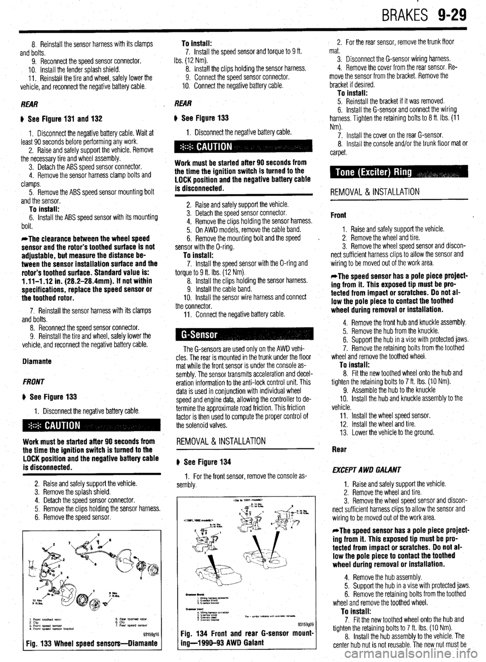
1 Front toothed rotor
2 Ckp
3 Front speed sensor
4 Front speed aenmr bracket t ;5’ toothed rotor ‘I Rear speed SB"SO,
93159016
Fig. 133 Wheel speed sensors-Diamante
11. Connect the negative battery cable.
The G-sensors are used only on the AWD vehi-
cles. The rear is mounted in the trunk under the floor
mat while the front sensor is under the console as-
sembly. The sensor transmits acceleration and decel-
eration information to the anti-lock control unit. This
data is used in conjunction with individual wheel
speed and engine data, allowing the controller to de-
termine the approximate road friction. This friction
factor is then used to compute the proper control of
the solenoid valves.
REMOVAL&INSTALLATION
# See Figure 134
1. For the front sensor, remove the console as-
sembly.
-lkol*)
1 wimp--vx
2 Gasnan I‘m”0
3. Gmwor LmcM
Bmar burl
: wwzh&T&m~mm-
6 G.smsol Ired Th, - ape.24 m-5 un Nt- vmsa*.
7 c-.elwnbRcta
93159909 Fig. 134 Front and rear G-sensor mount-
ing-l 990-93 AWD Galant
2. For the rear sensor, remove the trunk floor
mat.
3. Disconnect the G-sensor wiring harness.
4. Remove the cover from the rear sensor. Re-
move the sensor from the bracket. Remove the
bracket if desired.
To install: 5. Reinstall the bracket if it was removed.
6. Install the G-sensor and connect the wiring
harness. Tighten the retaining bolts to 8 ft. Ibs. (11
Nm).
7. Install the cover on the rear G-sensor.
8, Install the console and/or the trunk floor mat or
carpet.
REMOVAL & INSTALLATION
Front
1. Raise and safely support the vehicle.
2. Remove the wheel and tire.
3. Remove the wheel speed sensor and discon-
nect sufficient harness clips to allow the sensor and
wiring to be moved out of the work area.
*The speed sensor has a pole piece project-
ing from it. This exposed tip must be pro-
tected from impact or scratches. Do not al-
low the pole piece to contact the toothed
wheel during removal or installation.
4. Remove the front hub and knuckle assembly.
5. Remove the hub from the knuckle.
6. Support the hub in a vise with protected jaws.
7. Remove the retaining bolts from the toothed
wheel and remove the toothed wheel.
To install: 8. Fit the new toothed wheel onto the hub and
tighten the retaining bolts to 7 ft. Ibs. (10 Nm).
9. Assemble the hub to the knuckle
IO. Install the hub and knuckle assembly to the
vehicle.
11. Install the wheel speed sensor.
12. Install the wheel and tire.
13. Lower the vehicle to the ground.
Rear
EXCEPT AWD GALANT
1. Raise and safely support the vehicle.
2. Remove the wheel and tire.
3. Remove the wheel speed sensor and discon-
nect sufficient harness clips to allow the sensor and
wiring to be moved out of the work area.
*The speed sensor has a pole piece project-
ing from it. This exposed tip must be pro-
tected from impact or scratches. Do not al-
low the pole piece to contact the toothed
wheel during removal or installation.
4. Remove the hub assembly.
5. Support the hub in a vise with protected jaws.
6. Remove the retaining bolts from the toothed
wheel and remove the toothed wheel.
To install: 7. Fit the new toothed wheel onto the hub and
tighten the retaining bolts to 7 ft. Ibs. (10 Nm).
8. Install the hub assembly to the vehicle. The
center hub nut is not reusable. The new nut must be
Page 367 of 408
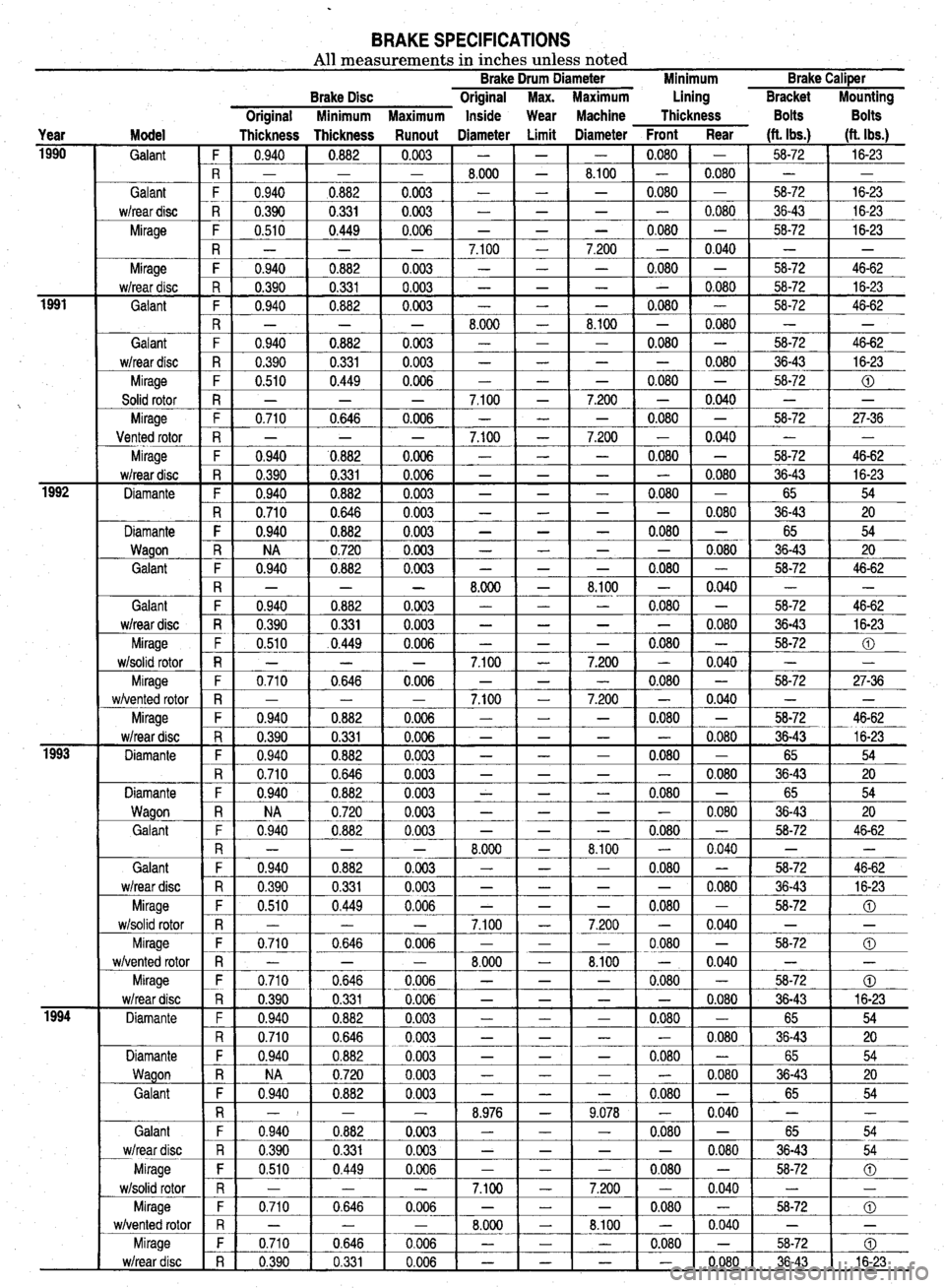
BRAKE SPECIFICATIONS All measurements in inches unless noted Brake Drum Diameter Minimum Brake CaliPer
Year Model
1990
Galant ~
Galant
w/rear disc
Mirage
1991
:
iiz- Mirage
w/rear disc
Galant
Galant
w/rear disc
Mirage
Solid rotor
Mirage
Vented rotor
Mirage
w/rear disc
Diamante
Diamante
Wagon
Galant
1993 Galant
w/rear disc
Mirage
w/solid rotor
Mirage
w/vented rotor
Mirage
w/rear disc
Diamante
Diamante
Wagon
Galant
im- Galant
w/rear disc
Mirage
w/solid rotor
Mirage
w/vented rotor
Mirage
w/rear disc
Diamante
Diamante
Wagon
Galant
Galant
w/rear disc
Mirage
w/solid rotor
Mirage
w/vented rotor
Mirage
w/rear disc Brake Disc Original Max. Maximum Lining Bracket
Miunting
Original Minimum Maximum Inside Wear Machine Thickness Bolts Bolts
Thickness Thickness Runout Diameter Limit Diameter Front Rear (ft. Ibs.)
(ft. Ibs.)
F 0.940
0.882 0.003 - - - 0.080 - 58-72
16-23
R - - - 8.000
- 8.100 - 0.080 - -
F 0.940
aO.882 0.003 - - - 0.080 - 58-72
16-23
R 0.390 0.331 0.003 -
- - - 0.080 36-43 16-23
F 0.510
0.449 0.006 - - - 0.080 - 58-72
16-23
R
- - - 7.100 - 7.200 - 0.040
- -
F 0.940 0.882 0.003 -
- - 0.080 - 58-72 46-62
R 0.390 0.331 0.003 -
- - - 0.080 58-72 16-23
F 0.940
0.882 0.003 - - - 0.080 - 58-72
46-62
R
_ - - 8.000 - 8.100 - 0.080
- -
F 0.940 0.882 0.003 -
- - 0.080 - 58-72 46-62
R 0.390 0.331 0.003 -
- - - 0.080 36-43 16-23
F 0.510
0.449 0.006 - - - 0.080 - 58-72
0
R - - - 7.100
- 7.200 - 0.040 - -
F 0.710 0.646 0.006 -
- - 0.080 - 58-72 27-36
R - - - 7.100
- 7.200 - 0.040 - -
F 0.940
'0.882 0.006 - - - 0.080 - 58-72
46-62
R 0.390
0.331 0.006 - - - - 0.080 36-43
16-23
F 0.940 0.882 0.003 -
- - 0.080 - 65 54
R 0.710
0.646 0.003 - - - - 0.080 36-43
20
F 0.940 0.882 0.003 -
- - 0.080 - 65 54
R
NA 0.720 0.003 - - - - 0.080
36-43 20
F 0.940 0.882 0.003 -
- - 0.080 - 58-72 46-62
R
- _ - 8.000 - 8.100 - 0.040
- -
F 0.940
0.882 0,003 - - - 0.080 -
58-72 46-62
R 0.390
0.331 0.003 - - - - 0.080
36-43 16-23
F 0.510
.0.449 0.006 - - - 0.080 -
58-72 0
R - - - 7.100
- 7.200 - 0.040 - -
F 0.710
0.646 0.006 - - - 0.080 -
58-72 27-36
R - - - 7.100
- 7.200 - 0.040 - -
F 0.940 0.882 0.006 -
- - 0.080 - 58-72 46-62
R 0.390
0.331 0.006 - - - - 0.080
36-43 16-23
F 0.940 0.882 0.003 -
- - 0.080 - 65 54
R 0.710
0.646 0.003 - - - - 0.080
36-43 20
F 0.940
0.882 0.003 - - - 0.080 -
65 54
R
NA 0.720 0.003 - - - - 0.080
36-43 20
F 0.940 0.882 0.003 -
- -- 0.080 - 58-72 46-62
R
- - - 8.000 - 8.100 - 0.040
- -
F 0.940
0.882 0.003 - - - 0.080 -
58-72 46-62
R 0.390 0.331 0.003 -
- - - 0.080 36-43 16-23
F 0.510 0.449 0.006 -
- - 0.080 - 58-72 0
R _ _ - 7.100
- 7.200 - 0.040 - -
F 0.710
0.646 0.006 - - - 0.080 -
58-72 0
R
_ - - 8.000 - 8.100 - 0.040
- -
F 0.710
0.646 0.006 - - - 0.080 -
58-72 CD
R 0.390
0.331 0.006 - - - - 0.080
36-43 16-23
F
0.940 0.882 0.003 - - - 0.080 -
65 54
R 0.710 0.646 0.003 -
- - - 0.080 36-43 20
F 0.940 0.882 0.003 -
- - 0.080 - 65 54
R
NA 0.720 0.003 - - - - 0.080
36-43 20
F 0.940 0.882 0.003 -
- - 0.080 - 65 54
R -I - - 8.976
- 9.078 - 0.040 - -
F 0.940 0.882 0.003 -
- - 0.080 - 65 54
R
0.390 0.331 0.003 - - - - 0.080
36-43 54
F 0,510 0.449 0.006 -
- - 0.080 - 58-72 0
R
_ _ - 7.100 - 7.200 - 0.040
- -
F 0.710 0.646 0.006 -
- - 0.080 - 58-72 0
R
- - - 8.000 - 8.100 - 0.040
- -
F
0.710 0.646 0.006 - - - 0.080 -
58-72 0
R 0.390 0.331 0.006 -
- - - 0.080 36-43 16-23
Page 368 of 408
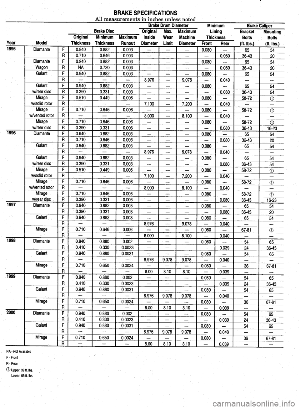
BRAKE SPECIFICATIONS All measurements in inches unless noted Brake Drum Diameter
Brake Disc Original Max. Maximum Minimum Brake Caliper
Lining
Bracket Mounting
Year
1995
1996
1997
isi-
1999
2ooo Original Minimum Maximum Inside
Wear Machine
Thickness Bolts
Bolts
Model
Thickness Thickness Runout Diameter Limit Diameter Front Rear Ht. Ibs.1
Diamante 1 (ft. Ibs.)
F 1 0.940 1 0.882 1 0.003 1 - 1 -
- 54 -
R 0.710 0.646 0.003 - -
Diamante F 0.940 0.882 0.003 - -
Wagon R NA 0.720 0.003 - -
Galant F 0.940 0.882 0.003 - - 0.080
-
0.080
-
-
0.080
-
--iizG-
-
0.040 ' I
65
36-43 20
65 54
36-43 20
65 54
- -
65 54
36-43 54
58-72 0
-
-
t- 0
-
.710 1 0.646 1 0.006 1 -
- 1 0.080 1
- 1 56-72 1 @
-
-
-
-
0.080 R - - - 8.976 -
Galant F 0.940 0.882 0.003 - -
wheardisc R 0.390 0.331 0.003 - -
Mirage F 0.510 0.449 0.006 - - 9.078
- -
0.080
- -
-
0.080
w/solid rotor
7.200
-
8.100 Mirage
w/vented rotor
Mirage
w/rear disc
Diam 1 R 1 0.390 1 0.331 1 0.006 I -
t--=-E5 1 -t-xii- 54
ante F 0.940 0.882 0.003 - - - 0.080 - 65
R 0.710 0.646 0.003 - - - - 0.080 36-43
20
Galant
Galant
wheardisc
Mirage
w/solid rotor
-
-
-
Mirage 1
wivente
d rotor -
‘ge
*disc 8.100 - 0.040 - -
- 0.080 -
58-72 0
- - 0.080 36-43 16-23 Mira - w/rear - -
Diamante F 0.940 0.882 0.003 - - - 0.080 -
65 54
R 0.390 0.331 0.003 - - - - 0.080
36-43 20
Galant F 0.940 0.882 0.003 - - -
0.l
380 - 65 54
R - - - 8.976 - 9.078 - 0.040 - -
Mirage F 0.710 0,646 0.006 - - -
0.l
380 - 67-81 0
PI
InI * n-a
- - - 1 LI.uuu 1 1 A #-A
- 8.1UU 1 - 0.040 - -
Diamante F 1 PPP- 0
t-t- R 0 ,940 0.880 0.002 - - - 0.080 - 54
65
,410 0.330 0.0023 - - - - _
0.039 24
36-43
snt 1 F I 0.940 0.880 0.0031 - - - 0.080 -
54 65 Gdi
Mirage
Diamante
Galant
R ' - _ - 8.976 9.078 9.078 -
0.040 L -
F 0.710 0.650 0.0024 - - - 0.080 - 36 67-81
R - - - 8.00 8.10 8.10 - 0.039 - -
F 0.940 0.880 0.002 - 1 - -
0.080 -
54 65
R 0
F 0
Mir;
Diamante
Galant I.410 0.330 0.0023 - -
1.940 0.880 0.0031 - -
- -
-
8.976 9.078
0.710 0.650 0.0024 - - - -
0.039
-
0.080 -
9,078 -
0.040
-
0.080 - 24
54
-
36 36-43
65
-
67-81
R - _ - 8.00 8.10 8.10 - 0.039 ii -
F 0.940 0.880 0.002 - - -
0.080 -
54 65
R 0.410 0.330 0.0023 - - - -
0.039 24 36-43
F 0.940
0.880 0.0031 - - - 0.080 - 54
65
R - - - 8.976 9.078 9.078 - 0.040 - -
we F 0.710 0.650 0.0024 - - - 0.080 - 36 Mirl _
i 1 1 1 1 1 . I 1 I I
R - - - 8.00 1 8.10 8.10 -
1 0.039
1 1 ,r -
1
NA - Not Available
F - Front
R - Rear
OUpper:39fLIbs. , Lower: 65 ft. Ibs.
Page 393 of 408
TROUBLESHOOTlNGll-11
b. Driveshaft misaligned. Check for collapsed or damaged engine and transmission
mounts, and replace as necessary.
c. Driveshaft bent or out of balance. Replace damaged components and reinstall.
d. Driveshaft out of balance. Remove the driveshaft and have it balanced by a competent
professional, or replace the driveshaft assembly.
NOTE: Most driveshafts are linked together by universal joints; however,
some manufacturers use Constant Velocity (CV) joints or rubber flex cou-
plers.
All Wheel and Four Wheel Drive Vehicles
1. Front or rear wheel makes a clicking noise
a. Check for debris such as a pebble, nail or glass in the tire or tire tread. Carefully re-
move the debris. Small rocks and pebbles rarely cause a puncture; however, a sharp
object should be removed carefully at a facility capable of performing tire repairs.
b. Check for a loose, damaged or worn Constant Velocity (CV) joint and replace if defec-
tive.
2. Front or rear wheel vibrates wlth Increased speed
a. Check for a bent rim and replace, if damaged.
b. Check the tires for balance or internal damage and replace if defective.
c. Check for a loose, worn or damaged wheel bearing and replace if defective.
d. Check for a loose, damaged or worn Constant Velocity (CV) joint and replace if defec-
tive.
Front Wheel Drive Vehicles
3. Front wheel makes a c&kin@ noise
a. Check for debris such as a pebble, nail or glass in the tire or tire tread. Carefully re-
move the debris. Small rocks and pebbles rarely cause a puncture; however, a sharp
object should be removed carefully at a facility capable of performing tire repairs.
b. Check for a loose, damaged or worn Constant Velocity (CV) joint and replace if defec-
tive. 4. Rear wheel makes a clicking noise
a. Check for debris such as a pebble, nail or glass in the tire or tire tread. Carefully re-
move the debris. Small rocks and pebbles rarely cause a puncture; however, a sharp
object should be removed carefully at a facility capable of performing tire repairs.
Rear Wheel Drive Vehicles
5. Front or rear wheel makes a clicking noise
a. Check for debris such as a pebble, nail or glass in the tire or tire tread. Carefully re-
move the debris. Small rocks and pebbles rarely cause a puncture; however, a sharp
object should be removed carefully at a facility capable of performing tire repairs.
6. Rear wheel shudders or vibrates
a. Check for a bent rear wheel or axle assembly and replace defective components.
b. Check for a loose, damaged or worn rear wheel bearing and replace as necessary.
1. Burning odor from center of vehicle when accelerating
a. Check for a seizing brake hydraulic component such as a brake caliper. Check the
caliper piston for surface damage such as rust, and measure for out-of-round wear
and caliper-to-piston clearance. For additional information on brake related odors, re-
fer to section 3-A, condition number 9.
b. On vehicles with a manual transmission, check for a slipping clutch. For possible
causes and additional information, refer to section Z-C, condition number 1.
c. On vehicles with an automatic transmission, check the fluid level and condition, Top
off or change the fluid and filter using the recommended replacement parts, lubricant
type and amount. If the odor persists, transmission removal and disassembly will be
necessary.
2. Engine accelerates, but vehicle does not gain speed
a. On vehicles with a manual transmission, check for a slipping or damaged clutch. For
possible causes and additional information refer to section Z-C, condition number 1.
b. On vehicles with an automatic transmission, check the fluid level and condition. Top
off or change the fluid and filter using the recommended replacement parts, lubricant
type and amount. If the slipping continues, transmission removal and disassembly will
be necessary.
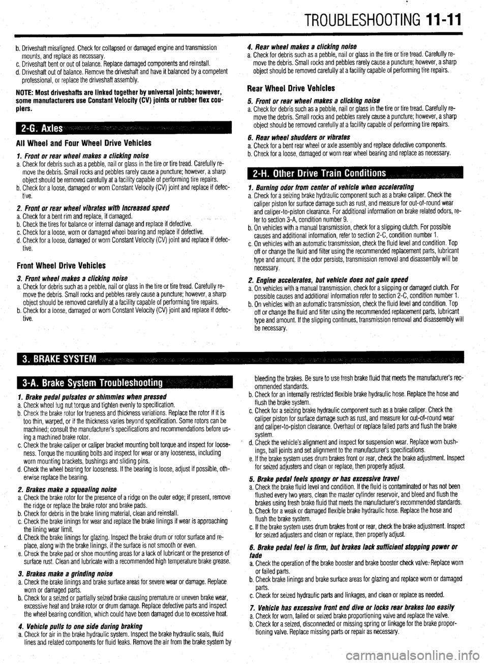
1. Brake pedal pulsates or shimmies when pressed
a. Check wheel lug nut torque and tighten evenly to specification.
b. Check the brake rotor for trueness and thickness variations. Replace the rotor if it is
too thin, warped, or if the thickness varies beyond specification. Some rotors can be
machined: consult the manufacturer’s specifications and recommendations before us-
ing a machined brake rotor.
c. Check the brake caliper or caliper bracket mounting bolt torque and inspect for loose-
ness. Torque the mounting bolts and inspect for wear or any looseness, including
worn mounting brackets, bushings and sliding pins.
d. Check the wheel bearing for looseness. If the bearing is loose, adjust if possible, oth-
erwise replace the bearing.
2. Brakes make a squealing noise
a. Check the brake rotor for the presence of a ridge on the outer edge; if present, remove
the ridge or replace the brake rotor and brake pads.
b. Check for debris in the brake lining material, clean and reinstall.
c. Check the brake linings for wear and replace the brake linings if wear is approaching
the lining wear limit.
d. Check the brake linings for glazing. Inspect the brake drum or rotor surface and re-
place, along with the brake linings, if the surface is not smooth or even.
e. Check the brake pad or shoe mounting areas for a lack of lubricant or the presence of
surface rust. Clean and lubricate with a recommended high temperature brake grease.
3. Brakes make a flrindinfl noise
a. Check the brake linings and brake surface areas for severe wear or damage. Replace
worn or damaged parts.
b. Check for a seized or partially seized brake causing premature or uneven brake wear,
excessive heat and brake rotor or drum damage. Replace defective parts and inspect
the wheel bearing condition, which could have been damaged due to excessive heat.
4. Vehicle pulls to one side during braking
a. Check for air in the brake hydraulic system. Inspect the brake hydraulic seals, fluid
lines and related components for fluid leaks. Remove the air from the brake system by bleeding the brakes. Be sure to use fresh brake fluid that meets the manufacturers rec-
ommended standards.
b. Check for an internally restricted flexible brake hydraulic hose. Replace the hose and
flush the brake system.
c. Check for a seizing brake hydraulic component such as a brake caliper. Check the
caliper piston for surface damage such as rust, and measure for out-of-round wear
and caliper-to-piston clearance. Overhaul or replace failed parts and flush the brake
system.
d. Check the vehicle’s alignment and inspect for suspension wear. Replace worn bush-
ings, ball joints and set alignment to the manufacturers specifications.
e. If the brake system uses drum brakes front or rear, check the brake adjustment. Inspect
for seized adjusters and clean or replace, then properly adjust.
5. Brake pedal feels spongy or has excessive travel
a. Check the brake fluid level and condition. If the fluid is contaminated or has not been
flushed every two years, clean the master cylinder reservoir, and bleed and flush the
brakes using fresh brake fluid that meets the manufacturers recommended standards.
b. Check for a weak or damaged flexible brake hydraulic hose. Replace the hose and
flush the brake system.
c. If the brake system uses drum brakes front or rear, check the brake adjustment. Inspect
for seized adjusters and clean or replace, then properly adjust.
6. Brake pedal feel is firm, but brakes lack sufficient stopping power or
fade
a. Check the operation of the brake booster and brake booster check valve: Replace worn
or failed parts.
b. Check brake linings and brake surface areas for glazing and replace worn or damaged
parts.
c. Check for seized hydraulic parts and linkages, and clean or replace as needed.
7. Vehicle has excessive front end dive or locks rear brakes too easily
a. Check for worn, failed or seized brake proportioning valve and replace the valve.
b. Check for a seized, disconnected or missing spring or linkage for the brake propor-
tioning valve. Replace missing parts or repair as necessary.
Page 399 of 408
GLOSSARY 11-17
AIR/FUEL RATIO: The ratio of air-to-gasoline by weight in the fuel mixture
drawn into the engine.
AIR INJECTION: One method of reducing harmful exhaust emissions by in-
jecting air into each of the exhaust ports of an engine. The fresh air entering
the hot exhaust manifold causes any remaining fuel to be burned before it can
exit the tailpipe.
ALTERNATOR: A device which produces AC (alternating current) which is
converted to DC (direct current) to charge the car battery.
AMMETER: An instrument, calibrated in amperes, used to measure the flow
of an electrical current in a circuit. Ammeters are always connected in series
with the circuit being tested.
AMPERE: The rate of flow of electrical current present when one volt of elec-
trical pressure is applied against one ohm of electrical resistance.
ANALOG COMPUTER: Any microprocessor that uses similar (analogous)
electrical signals to make its calculations.
ARMATURE: A laminated, soft iron core wrapped by a wire that converts elec-
trical energy to mechanical energy as in a motor or relay. When rotated in
a magnetic field, it changes mechanical energy into electrical energy as in a
generator.
ATMOSPHERIC PRESSURE: The pressure on the Earth’s surface caused
by the weight of the air in the atmosphere. At sea level, this pressure is 14.7
psi at 32°F (101 kPa at OOC).
ATOMIZATION: The breaking down of a liquid into a fine mist that can be
suspended in air.
AXIAL PLAY: Movement parallel to a shaft or bearing bore.
BACKFIRE: The sudden combustion of gases in the intake or exhaust sys-
tem that results in a loud explosion.
BACKLASH: The clearance or play between two parts, such as meshed gears.
BACKPRESSURE: Restrictions in the exhaust system that slow the exit of
exhaust gases from the combustion chamber.
BAKELITE[reg]: A heat resistant, plastic insulator material commonly used
in printed circuit boards and transistorized components.
BALL BEARING: A bearingmade up of hardened inner and outer races be-
tween which hardened steel’balls roll.
BALLAST RESISTOR: A resistor in the primary ignition circuit that lowers
voltage after the engine is started to reduce wear on ignition components.
BEARING: A friction reducing, supportive device usually located between a
stationary part and a moving part.
BI-METAL TEMPERATURE SENSOR: Anv sensor or switch made of two
dissimilar types of metal that bend when heated or cooled due to the different
expansion rates of the alloys. These types of sensors usually function as an
on/off switch. BLOW-BY: Combustion gases, composed of water vapor and unburned fuel,
that leak past the piston rings into the crankcase during normal engine oper-
ation. These gases are removed by the PCV system to prevent the buildup of
harmful acids in the crankcase.
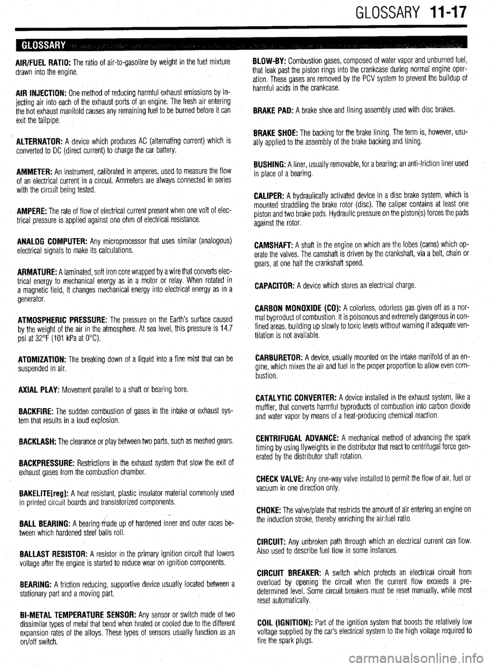
BRAKE PAD: A brake shoe and lining assembly used with disc brakes.
BRAKE SHOE: The backing for the brake lining. The term is, however, usu-
ally applied to the assembly of the brake backing and lining.
BUSHING: A liner, usually removable, for a bearing; an anti-friction liner used
in place of a bearing.
CALIPER: A hydraulically activated device in a disc brake system, which is
mounted straddling the brake rotor (disc). The caliper contains at least one
piston and two brake pads. Hydraulic pressure on the piston(s) forces the pads
against the rotor.
CAMSHAFT: A shaft in the engine on which are the lobes (cams) which op-
erate the valves. The camshaft is driven by the crankshaft, via a belt, chain or
gears, at one half the crankshaft speed.
CAPACITOR: A device which stores an electrical charge.
CARBON MONOXIDE (CO): A colorless, odorless gas given off as a nor-
mal byproduct of combustion. It is poisonous and extremely dangerous in con-
fined areas, building up slowly to toxic levels without warning if adequate ven-
tilation is not available.
CARBURETOR: A device, usually mounted on the intake manifold of an en-
gine, which mixes the air and fuel in the proper proportion to allow even com-
bustion
CATALYTIC CONVERTER: A device installed in the exhaust system, like a
muffler, that converts harmful byproducts of combustion into carbon dioxide
and water vapor by means of a heat-producing chemical reaction.
CENTRIFUGAL ADVANCE: A mechanical method of advancing the spark
timing by using flyweights in the distributor that react to centrifugal force gen-
erated by the distributor shaft rotation.
CHECK VALVE: Any one-way valve installed to permit the flow of air, fuel or
vacuum in one direction only.
CHOKE: The valve/plate that restricts the amount of air entering an engine on
the induction stroke, thereby enriching the air:fuel ratio.
CIRCUIT: Any unbroken path through which an electrical current can flow.
Also used to describe fuel flow in some instances.
CIRCUIT BREAKER: A switch which protects an electrical circuit from
overload by opening the circuit when the current flow exceeds a pre-
determined level. Some circuit breakers must be reset manually, while most
reset automatically.
COIL (IGNITION): Part of the ignition system that boosts the relatively low
voltage supplied by the car’s electrical system to the high voltage required to
fire the spark plugs.
Page 400 of 408
11-18 GLOSSARY
COMBINATION MANIFOLD: An assembly which includes both the intake
and exhaust manifolds in one casting.
COMBINATION VALVE: A device used in some fuel systems that routes fuel
vapors to a charcoal storage canister instead of venting them into the atmos-
phere. The valve relieves fuel tank pressure
and allows fresh air into the tank
as the fuel level drops to prevent a vapor lock situation.
COMPRESSION RATIO: The ratio of the volume between the piston and
cylinder head when the piston is at the bottom of its stroke (bottom dead cen-
ter) and when the piston is at the top of its stroke (top dead center).
CONDENSER: 1. An electrical device which acts to store an electrical charge,
preventing voltage surges. 2. A radiator-like device in the air conditioning sys-
tem in which refrigerant gas condenses into a liquid, giving off heat.
CONDUCTOR: Any material through which an electrical current can be trans-
mitted easily.
CONTINUITY: Continuous or complete circuit. Can be checked with an ohm-
meter.
COUNTERSHAFT: An intermediate shaft which is rotated by a mainshaft and
transmits, in turn, that rotation to a working part.
CRANKCASE: The lower part of an engine in which the crankshaft and re-
lated parts operate.
CRANKSHAFT: Engine component (connected to pistons by connecting rods)
which converts the reciprocating (up and down) motion of pistons to rotary
motion used to turn the driveshaft.
CYLINDER: In an engine, the round hole in the engine block in which the
piston(s) ride.
CYLINDER BLOCK: The main structural member of an engine in which is
found the cylinders, crankshaft and other principle parts.
DEAD CENTER: The extreme top or bottom of the piston stroke.
DETONATION: An unwanted explosion of the air/fuel mixture in the com-
bustion chamber caused by excess heat and compression, advanced timing,
or an overly lean mixture. Also referred to as “ping”.
DIAPHRAGM: A thin, flexible wall separating two cavities, such as in a vac-
uum advance unit.
c
DIESELING: The engine continues to run after the car is shut off; caused by
fuel continuing to be burned in the combustion chamber.
DIFFERENTIAL: A geared assembly which allows the transmission of mo-
tion between drive axles, giving one axle the ability to rotate faster than the
other, as in cornering.
DIODE: An electrical device that will allow current to flow in one direction
only.
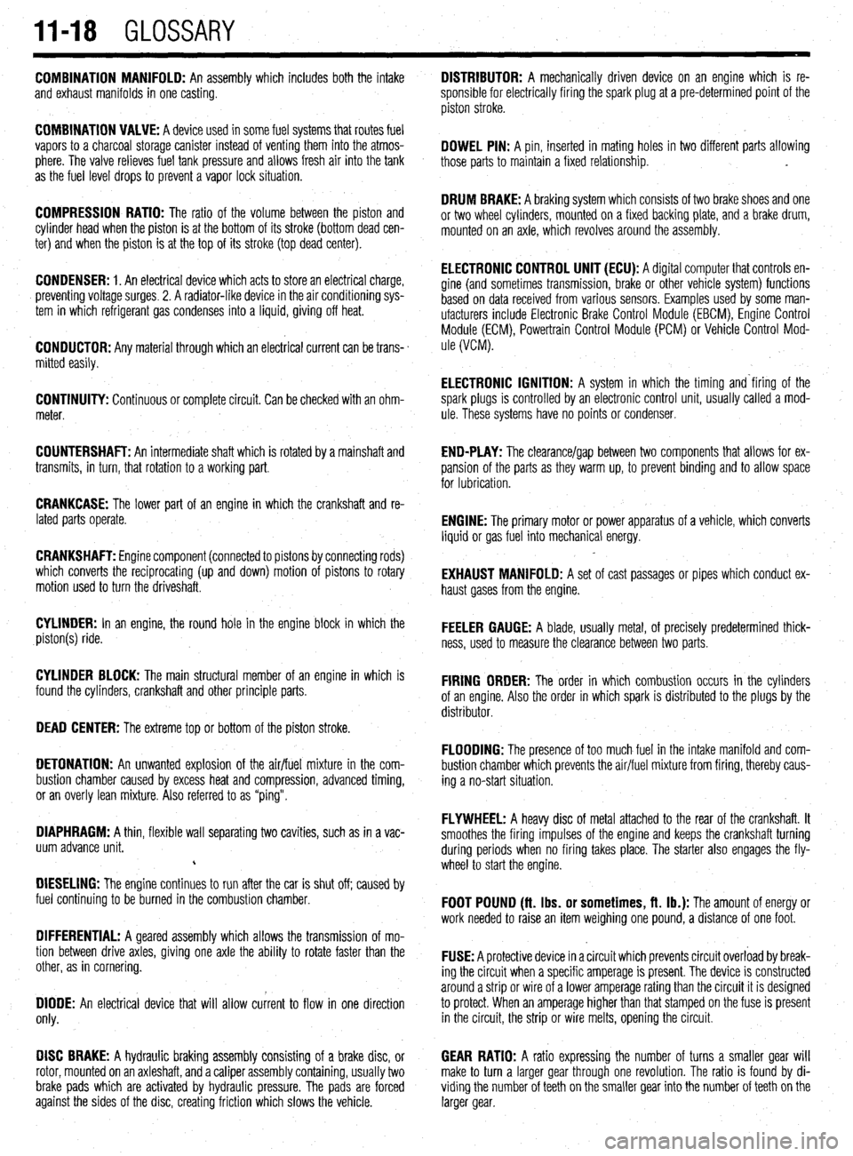
DISC BRAKE: A hydraulic braking assembly consisting of a brake disc, or
rotor, mounted on an axleshaft, anda caliper assembly containing, usually two GEAR RATIO: A ratio expressing the number of turns a smaller gear will
make to turn a larger gear through one revolution. The ratio is found by di-
brake pads which are activated by hydraulic pressure. The pads are forced viding the number of teeth on the smaller gear into the number of teeth on the
against the sides of the disc, creating friction which slows the vehicle. larger gear. DISTRIBUTOR: A mechanically driven device on an engine which is re-
sponsible for electrically firing the spark plug at a pre-determined point of the
piston stroke.
DOWEL PIN: A pin, inserted in mating holes in two different parts allowing
those parts to maintain a fixed relationship. .
DRUM BRAKE: A braking system which consists of two brake shoes and one
or two wheel cylinders, mounted on a fixed backing plate, and a brake drum,
mounted on an axle, which revolves around the assembly.
ELECTRONIC CONTROL UNIT (ECU): A diqital computer that controls en-
gine (and sometimes transmission‘, brake or other vehicle system) functions
based on data received from various sensors. Examples used by some man-
ufacturers include Electronic Brake Control Module (EBCM), Engine Control
Module (ECM), Powertrain Control Module (PCM) or Vehicle Control Mod-
ule (VCM).
ELECTRONIC IGNITION: A system in which the timing and‘firing of the
spark plugs is controlled by an electronic control unit, usually called a mod-
ule. These systems have no points or condenser,
END-PLAY: The clearance/gap between two components that allows for ex-
pansion of the parts as they warm up, to prevent binding and to allow space
for lubrication.
ENGINE: The primary motor or power apparatus of a vehicle, which converts
liquid or gas fuel into mechanical energy.
EXHAUST MANIFOLD: A set of cast passages or pipes which conduct ex-
haust gases from the engine.
FEELER GAUGE: A blade, usually metal, of precisely predetermined thick-
ness, used to measure the clearance between two parts.
FIRING ORDER: The order in which combustion occurs in the cylinders
of an engine. Also the order in which spark is distributed to the plugs by the
distributor.
FLOODING: The presence of too much fuel in the intake manifold and com-
bustion chamber which prevents the air/fuel mixture from firing, thereby caus-
ing a no-start situation.
FLYWHEEL: A heavy disc of metal attached to the rear of the crankshaft. It
smoothes the firing impulses of the engine and keeps the crankshaft turning
during periods when no firing takes place. The starter also engages the fly-
wheel to start the engine.
FOOT POUND (ft. Ibs. or sometimes, ft. lb.): The amount of energy or
work needed to raise an item weighing one pound, a distance of one foot.
FUSE: A protective device in a circuit which prevents circuit overload by break-
ing the circuit when a specific amperage is present. The device is constructed
around a strip or wire of a lower amperage rating than the circuit it is designed
to protect. When an amperage higher than that stamped on the fuse is present
in the circuit, the strip or wire melts, opening the circuit.