1900 MITSUBISHI DIAMANTE airbag
[x] Cancel search: airbagPage 210 of 408
I I
CHASSIS ELECTRICAL 6-7
When working on any electrical component on the
vehicle, it is always a good idea to disconnect the
negative (-) battery cable. This will prevent potential
damage to many sensitive electrical components
such as the Powertrain Control Module (PCM), radio,
alternator, etc.
*Any time you disengage the battery cables,
it is recommended that you disconnect the negative (-) battery cable first. This will pre-
vent your accidentally grounding the positive
(+) terminal to the body of the vehicle when
disconnecting it, thereby preventing damage
to the above mentioned components.
Before you disconnect the cable(s), first turn the
ignition to the OFF position. This will prevent a draw
on the battery which could cause arcing (electricity
trying to ground itself to the body of a vehicle, just
like a spark plug jumping the gap) and, of course, damaging some components such as the alternator
diodes.
When the battery cable(s) are reconnected (nega-
tive cable last), be sure to check that your lights,
windshield wipers and other electrically operated
safety components are all working correctly. If your
vehicle contains an Electronically Tuned Radio (ETR),
don’t forget to also reset your radio stations. Ditto for
the clock.
SERVICE PRECAUTIONS
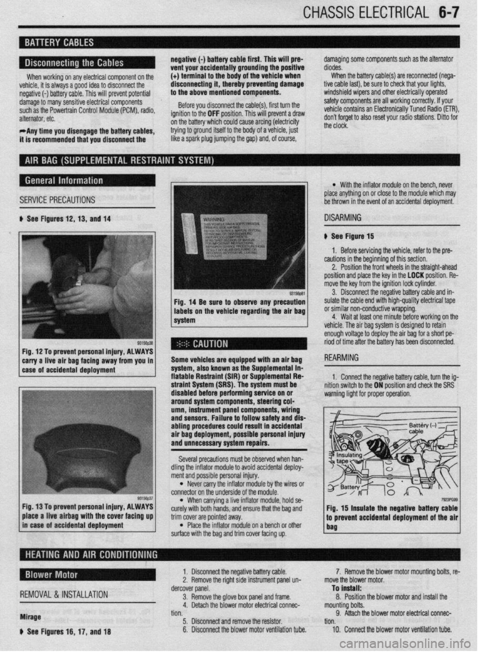
b See Figures 12,13, and 14
Fig, 14 Be sure to observe any precaution
labels on the vehicle regarding the air bag
system
Fig. 12 To prevent personal injury, ALWAYS
*
carry a-live -ah bag fac!ng away from you in 1
1 case of accidental deployment Some vehicles are equipped wtth an air bag
-.-‘--
syr1em, aiscl Known as I11 -I-- ‘------- -- sLe Supplemental in- fiatable Restraint (SIR) o r Suouiementai Fiea
l With the inflator module on the bench, never
place anything on or close to the module which may
be thrown in the event of an accidental deployment.
DISARMING
# See Figure 15
1. Before servicing the vehicle, refer to the pre-
cautions in the beginning of this section.
2. Position the front wheels in the straight-ahead
position and place the key in the LOCK position. Re-
move the key from the ignition lock cylinder.
3. Disconnect the negative battery cable and in-
sulate the cable end with high-quality electrical tape
or similar non-conductive wrapping.
4. Wait at least one minute before working on the
vehicle. The air baa svstem is desianed to retain
enough voltage to deploy the air bag for a short pe-
riod of time after the battery has been disconnected.
1. Connect the neoative batters cable. turn the ia-
3, hold se-
e bag and
trim cover are pointed away.
l Place the inflator module on a bench or other
surface with the bag and trim cover facing up.
7!r!3PG93 Fig. 15 insulate the negative battery cable
.I
to prevent accidental deployment of the air
bag place a live airbag with the cover facing up
in case of accidental deployment
REMOVAL &INSTALLATION
Mirage
b See Figures 16, 17, and 18 1. Disconnect the negative battery cable.
2. Remove the right side instrument panel un-
dercover panel.
3. Remove the glove box panel and frame.
4. Detach the blower motor electrical connec-
tion.
5. Disconnect and remove the resistor.
6. Disconnect the blower motor ventilation tube. 7. Remove the blower motor mounting bolts, re-
move the blower motor.
To install:
8. Position the blower motor and install the
mounting bolts.
9. Attach the blower motor electrical connec-
tion.
10. Connect the blower motor ventilation tube.
Page 324 of 408
. . . ,.x ..-~ .-....,, _s_s”., .._ ” *
8-28 SUSPENSION AND STEERING
REMOVAL&INSTALLATION
199%93 Mirage 1994-00 Mirage and Galant
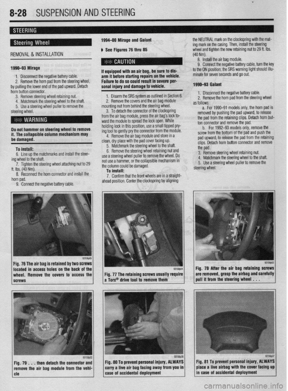
b See Figures 76 thru 85 the NEUTRAL mark on the clockspring with the mat-
f ing mark on the casing. Then, install the steering
wheel and tighten the new retaining nut to 29 ft. Ibs.
(40 Nm).
8. Install the air bag module.
1. Disconnect the negative battery cable.
2. Remove the horn pad from the steering wheel,
by pulling the lower end of the pad upward. Detach I
If aqui
arm it --.-.- ---.-...= .-r-.‘- -.. _..- ._.. - -
Failure to do so could result in severe per-
sonal injury and damage to vehicle. pped with an air bag, be sure to dls- hnfnra sfarfinn rmairs on the vehicle.
9. Connect the negative battery cable, turn the key
to the ON position; the SRS warning light should illu-
minate for seven seconds and go out.
1990-93 Galant
hbin butin connector.
3. Remove steering wheel retaining nut:
. . . .‘ .
a. .a I <.
4. Matcnmarlc me steering wneel to me snan.
5. Use a steering wheel puller to remove the
steering wheel.
Do not hammer on steering wheel to remove
it. The collapsible column mechanism may
ha rlsmwmd.
To install:
6. Line up the matchmarks and install the steer-
ing wheel to the shaft.
7. Ti flhten the steering wheel attaching nut to 29
ft. Ibs. (40 Nm).
8. Reconnect the horn connector and install the
horn pad.
9. Connect the neaative battetv cable. 1. Disarm the SRS system as outlined in Section 6.
^ m *I
sand the air bag module
.,A +L. m++-,g w,,eel,
*. I z. Remove me cover
mounting nut from behill” ~IK ~(G~G!I
3. To detach the connector of the clocKsprmfl
from the air bag module, press the air bag’s lock to-
ward the module to spread the lock open. While
holding lock in this position, use a small tipped pry-
ing tool to gently pry the connector from the module.
4. Remove the air bag module and store in a
clean, dry place with the pad cover facing up.
5. Matchmark the steering wheel to the shaft.
6. Remove the steering wheel retaining nut and
use a steering wheel puller to remove the wheel. Do
not use a hammer, or the collapsible mechanism in
the column could be damaged.
To install:
7. Confirm that the front wheels are in a straight-
ahead position. Center the clocksprinfl by aligning 1. Disconnect the negative battery cable.
2. Remove the horn oad from the steerino wheel
as follows:- - - - r d
a. For 1990-91 models only, the horn pad is
removed by pushing the pad upward, to release
the pad from the retaining clips. Detach horn but-
ton connector and remove the pad.
b.
For 1992-93 models only, remove the
screw from the bottom of the pad and push the
pad upward, to release the pad from the retaining
clips. Detach horn button connector and remove
the pad.
3. Remove steering wheel retaining nut.
4. Matchmark the steering wheel to the shaft.
5. Use a steering wheel puller to remove the
steering wheel.
Fig. 76 The air bag is retained by two 8
located in access holes on the back
wheel. Remove the covers to access the
screws Fig. 78 After the air baa
retainino screws
Fig. 77 The retaining screws usually require are removed, grasp the airbag andiarefully
a Torx@ drive tool to remove them pull it from the steering wheel . . .
then detach the connector and Fig. 80 To prevent personal injury, ALWAYS fig. 81 To prevent personal Injury, ALWAYS
ove the air bag module from the vehi- carry a live air bag facing away from you in place a live airbag with the cover facing up
Page 377 of 408
c BODYANDTRi'l IO-9
:: k% protector assembly
3. Knee protector support bracket
4. Column cover
5 Glove box striker
6 Glove box and glove box outer case
7 Under cover mstallatmn screw
8. Audio panel
9 Radio and tape player
10 Heater control panel
assembly 11 Cup holder
12. Speaker
13 Meter bezel
14 Combination meter
15 Speeoometer cable adapter
16 %&rrng column assembly rnstallatioh
17 Harness connector
18. Glove box kght swatch
19. Instrument panel assembly
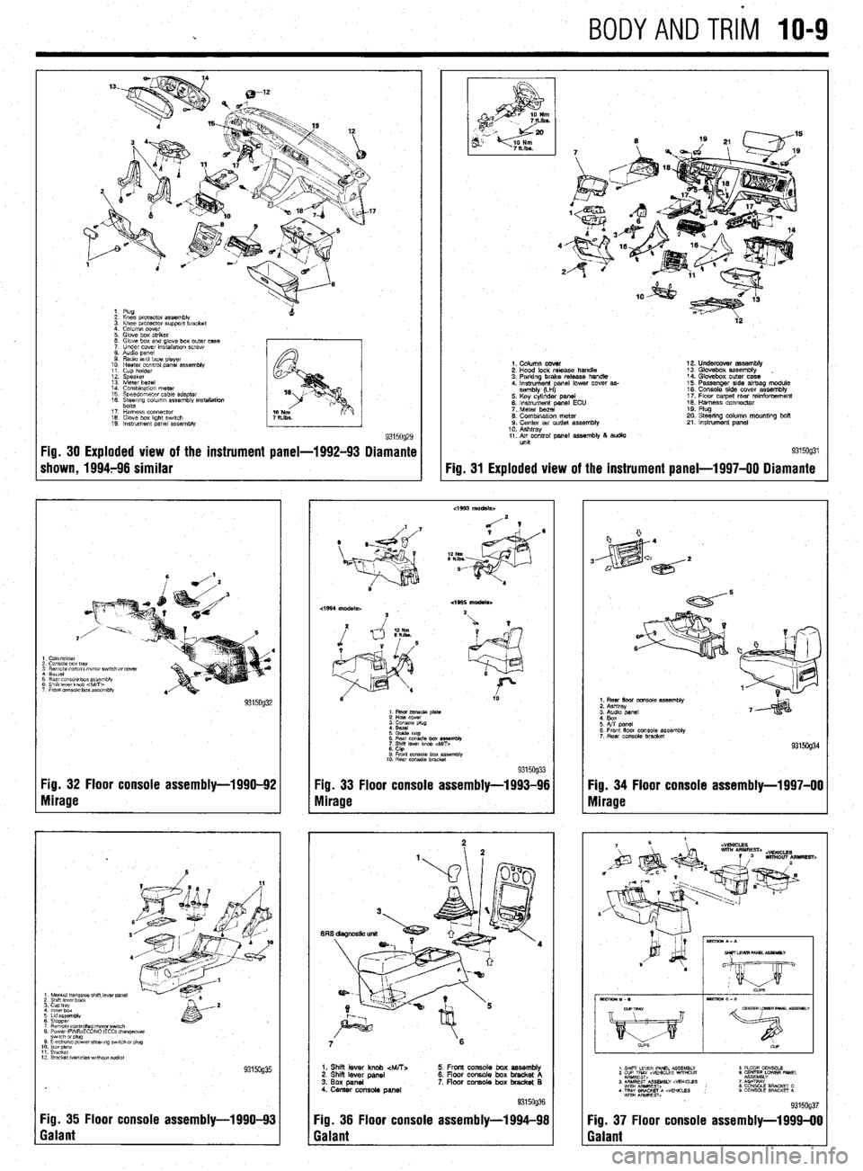
9315og29 Fig. 30 Exploded view of the instrument panel-1992-93 Diamante
shown, 1994796 similar
I Cam holder
2 Console box tray
3 Remote control mrror swatch drcover
1 Berrel
3 Rear cms~ie box assembly
3 Shift lever knob 4vitT>
7 Front eonsale box assembly
Fig. 32 Floor console assembly-1990-92
Yg. 33 Floor console assembly-1993-96
Nlirage
Mirage
1 Manual tmnsaxle shrft lever panel 2 Shrft lever boat 3. cup tray 4 lnnerbdx
6 Lrd assembly
6 Stopper 7 Remote cO”trOned nl,rrorSwl,Ch 8 PowerlFVWECONO (EC01 changeover
12 Bracket Wvcles wrthout addlo)
Fig. 35 Floor console assembly-l 990-93
Galant
4’
2
ia
9315og31 Fig. 31
Exploded view of the instrument
panel-l 997-00 Diamante
1. Column cover
2. Hood lock release handle
3. Parking brake release handle
4. Instrument anal lower cover as-
sembly (LH
P 5. Key cylinder panel
6. instrument panel ECU
7. Meter bezel
0. Combination meter 9. Center air outlet assembly
10. Ashtray
11. Air control panel assembly 8 audio
unit 12. Undercover assembly
13. Glovebox assembly
14. Glovebox outer case
15. Passenger side airbag module
16. Console side cover assemblv
17. Flow carpet rear rainforcem&t
18. Harness connector
19. Plug
20. Steering column mountlng bolt
21. Instrument panel
6 Rear cmsole box es%mbly
7
Shrff lever knob
6. CtQ 9 Front console box assembfk
10. Rear console bracket 9315og33
7 6
1. Shii lever knob &ATT:.
2. Shi lever panel
3. Box panel
4. Center console panel 5. Front console box assembly
6. Floor console box bracket A
7. floar console box bradret B
Fig. 36 Floor console assembly-1994-98
Galant
1. Rear floor console assembly
2. Ashtray
6. Front floor console assembly
7 Rear console bracket
Fig. 34 Floor console assembly-1997-00
Mirage
Fig. 37 Floor console assembly-l 999-00
Galant