1900 MITSUBISHI DIAMANTE diagram
[x] Cancel search: diagramPage 23 of 408
l-24 GENERALINFORMATIONAND MAINTENANCE
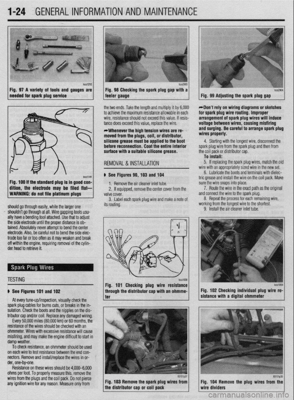
b%slZl2 Fig. 97 A variety of tools and gauges are
needed for spark plug service tm2903 Fig. 98 Checking the spark plug @au with a tccs2904 feeler gauge. - Fig. 99 Adjusting the spark plug gap
ig. 100 If the standard plug Is in good con-
ftlon, the electrode may be filed flat- the two ends. Take the length and multiply it by 6,000
to achieve the maximum resistance allowable in each
wire, resistance should not exceed this value. If resis-
tance does exceed this value, replace the wire.
*Whenever the high tension wires are re- ’
moved from the plugs, coil, or distributor,
silicone grease must be applied to the boot
before reconnection. Coat the entire Interior
surface with a suitable silicone grease.
REMOVAL &INSTALLATION
# See Figures 90,103 and 104
1. Remove the air cleaner inlet tube.
2. If eouiooed, remove the center cover from the
WARNING: do not file platinum plugs
valve covei.
3. Label each spark plug wire and make a note of
should go through easily, while the larger one its routing.
I’ shouldn’t go through at all. Wire gapping tools usu-
ally have a bending tool attached. Use that to adjust
the side electrode until the proper distance is ob-
tained. Absolutely never attempt to bend the center
electrode. Also, be careful not to bend the side elec- *Don’t rely on wiring diagrams or sketches
for spark plug wire routing. Improper
arrangement of spark plug wires will induce
voltage between wires, causing misfiring
and surging. Be careful to arrange spark plug
wires properly.
4. Starting with the longest wire, disconnect the
spark plug wire from the spark plug and then from
the coil pack or distributor cap.
To install:
5. If replacing the spark plug wires, match the olc
wire with an appropriately sized wire in the new set.
6. Lubricate the boots and terminals with dielec-
tric grease and install the wire on the coil pack. Make
sure the wire snaps into place.
a 7. Route the wire in the exact path as the original
nd connect the wire to the spark plug.
8. Repeat the process for each remaining wire,
iorking from the longest wire to the shortest.
9. Install the air cleaner inlet tube.
trode too far or too often as it may weaken and break
off within the engine, requiring removal of the cylin-
der head to retrieve it.
TESTING
# See Figures 191 and 102
At every tune-up/inspection, visually check the
spark plug cables for burns cuts, or breaks in the in-
sulation. Check the boots and the nipples on the dis-
tributor cap and/or coil. Replace any damaged wiring.
Every 50,000 miles (80,000 km) or 60 months, the
resistance of the wires should be checked with an
ohmmeter. Wires with excessive resistance will cause
misfiring, and may make the engine difficult to start in
damp weather.
To check resistance, an ohmmeter should be used ’
on each wire to test resistance between the end con-
nectors. Remove and install/replace the wires in or- ’
der, one-by-one.
Resistance on these wires should be 4,000-6,000
ohms per foot. To properly measure this, remove the
wires from the plugs and the coil pack. Do not pierce
any ignition wire for any reason. Measure only from Fig. 103 Remove the spark plug wires from
tcG1009 Fig. 102 Checking individual plug wire re-
sistance with a digital ohmmeter
Fig. 104 Remove the plug wires from the
wire dividers
Page 144 of 408
EMISSION CONTROLS 4-2
CRANKCASEVENTILATIONSYSTEM 4-2
OPERATION 4-2
COMPONENTTESTING 4-2
REMOVAL &INSTALLATION 4-2
EVAPORATIVEEMISSIONCONTROLS 4-2
OPERATION 4-2
COMPONENTTESTING 4-3
REMOVAL&INSTALLATION 4-4
EXHAUSTGASRECIRCULATION
SYSTEM 4-5
OPERATION 4-5
COMPONENTTESTING 4-5
REMOVAL&INSTALLATION 4-6
ELECTRONIC ENGINE CONTROLS 4-7
ENGlNECONTROLUNIT/POWERTRAIN
CONTROLMODULE(ECU/PCM) 4-7
OPERATION 4-7
REMOVAL&INSTALLATION 4-7
OXYGENSENSOR 4-8
OPERATION 4-8
TESTING 4-8
REMOVAL&INSTALLATION 4-8
IDLEAIRCONTROLMOTOR 4-9
OPERATION 4-9
TESTING 4-9
REMOVAL&INSTALLATION 4-9
ENGINECOOLANTTEMPERATURE
SENSOR 4-10
OPERATION 4-10
TESTING 4-10
REMOVAL&INSTALLATION 4-10
INTAKEAIRTEMPERATURESENSOR 4-10
OPERATION 4-10
TESTING 4-11
REMOVAL&INSTALLATION 4-11
MASSAIRFLOWSENSOR 4-11
OPERATION 4-11
TESTING 4-11
REMOVAL&INSTALLATION 4-11
MANIFOLDABSOLUTEPRESSURE
SENSOR 4-12
OPERATION 4-12
TESTING 4-12
REMOVAL&INSTALLATION 4-13
THROTTLEPOSITIONSENSOR 4-13
OPERATION 4-13
TESTING 4-13
REMOVAL&INSTALLATION 4-13
CAMSHAFT POSITIONSENSOR 4-14
OPERATION 4-14
TESTING 4-14
REMOVAL&INSTALLATION 4-14
CRANKSHAFTPOSlTlONSENSOR/CRANK
ANGLE SENSOR 4-14
OPERATION 4-14 I
TESTING 4-15 REMOVAL&INSTALLATION 4-15
COMPONENT LOCATIONS 4-16
OBD-1 TROUBLE CODES 4-26
GENERALINFORMATION 4-26
CHECKENGINVMALFUNCTION
INDICATOR LIGHT 4-26
SERVICEPRECAUTIONS 4-26
READING CODES 4-26
WITHASCANTOOL 4-26
WITHOUTASCANTOOL 4-27
CLEARINGCODES 4-27
DIAGNOSTICTROUBLECODES 4-27
OBD-II TROUBLE CODES 4-27
GENERALINFORMATION 4-27
READING CODES 4-27
WITHASCANTOOL 4-27
WITHOUTASCANTOOL 4-27
CLEARINGCODES 4-28
WITHASCANTOOL 4-28
WITHOUTASCANTOOL 4-28
DIAGNOSTICTROUBLECODES 4-28
FLASH OUTCODELIST 4-32
VACUUM DIAGRAMS 4-36
Page 148 of 408
,
DRIVEABILITYAND EMISSIONS CONTROLS 4-5
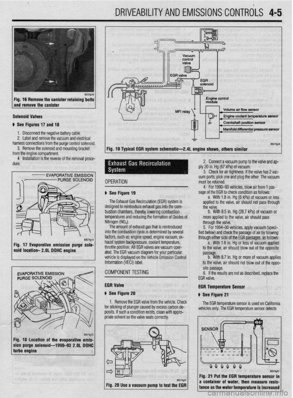
Fig. 16 Remove the canister retaining bolts
and remove the canister
Solenoid Valves
u See Figures 17 and 18
1 b Disconnect the negative battery cable.
2. Label and remove the vacuum and electrical
harness connections from the purge control solenoid.
3. Remove the solenoid and mounting bracket
from the engine compartment.
4. Installation is the reverse of the removal proce-
dure.
I
- EVAPORATIVE EMISSION
Fig. 18 location of the evaporative emis-
purge solenoid-1990-93 2.OL DDHC
Volume air flow seneftr I
I Manifold diierential pressure m
&a$34
Fig. 19 Typical EGR system schematie-2.4L engine shown, others similar
IPERATION uum ports; pick one and plug the other. The vacuum
must be retained.
1 See Figure 19
The Exhaust Gas Recirculation (EM) system is
lesigned to reintroduce exhaust gas into the com-
ttii valve.
rustion chambers, thereby lowering combustion b. With 8.5 in. Hg (28.7 kPa) of vacuum or
emperatures and reducing the formation of Oxides of more applied to the valve, air should pass 4. For 1990-93 vehicles. blow air from 1 oas-
sage of the EGR to check condition as foffows--
a. With 1.8 in. Hg (6 kPa) of vacuum or less
aoolied to the valve. air should not oass throuah
litrogen (NO,).
The amount of exhaust gas that is reintroduced
Ito the combustion cycle is determined by several
actors, such as: engine speed, engine vacuum, ex-
raust system backpressure, coolant temperature,
Irottle position. All EGR valves are vacuum oper-
ted. The EGR vacuum diagram for your particular
chicle is displayed on the Vehicle Emission Control
iformation (VECI) label. through the valve.
5. For 1994-00 vehicles, apply vacuum (speci-
fied below) and check the passage of air by blowing
through either side of the EGR passages, as follows:
a. With 1 .?I in. Hg or less of vacuum applied
to the valve, air should blow out of the opposite
passa e.
b. %ith 8.7 in. Hg or more of vacuum applies
to the valve, air should not blow out of the oppo-
:OMPONENTTESTiNG site passage.
6. If the results are not as described, replace the
EGR valve.
iGR Valve
t See Figure 20
1. Remove the EGR valve from the vehicle. Check
I”..““.
:or sticking of plunger caused by excess carbon de-
losits. If such a condition exists, clean with appro- EGR Temperature Lan*nr
u See Figure 21
The EGR temperature sensor is used on California
vehicles only. The EGR temperature sensor detects
Fig. 20 Use a vacuum pump to test the EGR
I I
a coni tance i of water. then measure resis-
I ms the water temperature is increased
Page 179 of 408
4-36 DRIVEABILITYAND EMISSIONS CONTROLS
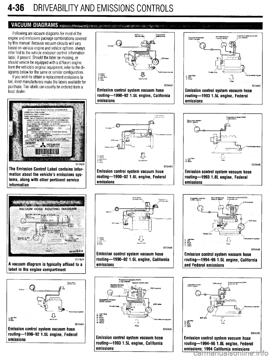
Following are vacuum magrams for most of the
engine and emissions package combinations covered
by this manual Because vacuum circuits will vary
based on various engine and vehicle options, always
refer first to the vehicle emission control Information
label, if present. Should the label be missing, or
should vehicle be equipped with a different engine
from the vehicle’s original equipment, refer to the di-
agrams below for the same or similar configuration.
If you wish to obtain a replacement emissions la-
bel, most manufacturers make the labels available for
lurchase. The labels can usually be ordered from a
ocal dealer.
A vacuum diagram is typically affixed to a
label in the engine compartment
93154voI Emission control system vacuum hose
routing-1990-92 1.5L engine, Federal
emissions
93154vul Emission control system vacuum hose
routing-1990-92 1.5L engine, California
emissions
Emission control system vacuum hose
routing-1990-92 1.6L engine, Federal
emissions
Emission control system vacuum hose
routing-1990-92 1.6L engine, California
emissions
Emission control system vacuum hose
routing-1993 1.5L engine, California
emissions
I
r
I I
1 I
Emission control system vacuum hose
routing-1993 1.5L engine, Federal
emissions
-
Emission control system vacuum hose
‘outing-1993 1.6L engine, Federal
rmissions
93154vo8 Emission control system vacuum hose
routing-1994-96 1.5L engine. California
and Federal emissions -
routing-1994-96 1.8L engine, Federal
emissions; 1994 California emissions
Page 204 of 408
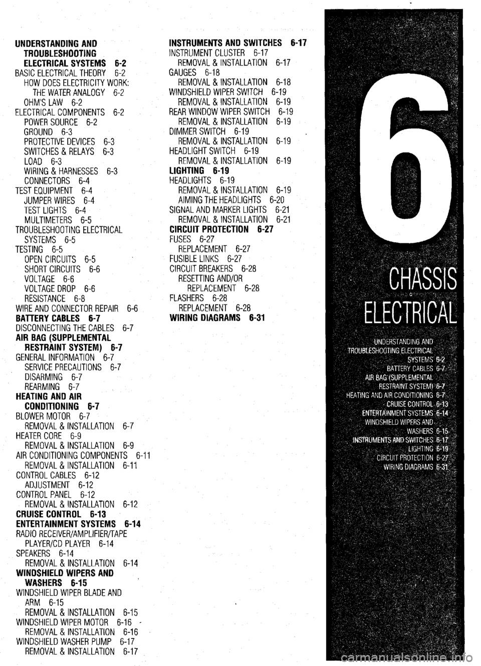
UNDERSTANDING AND
TROUBLESHOOTING
ELECTRICAL SYSTEMS 6-2
BASIC ELECTRICALTHEORY 6-2
HOW DOES ELECTRICITY WORK:
THEWATERANALOGY 6-2
OHM'S LAW 6-2
ELECTRICALCOMPONENTS 6-2
POWERSOURCE 6-2
GROUND 6-3
PROTECTIVE DEVICES 6-3
SWITCHES&RELAYS 6-3
LOAD 6-3
WIRING & HARNESSES 6-3
CONNECTORS 6-4
TEST EQUIPMENT 6-4
JUMPER WIRES 6-4
TEST LIGHTS 6-4
MULTIMETERS 6-5
TROUBLESHOOTING ELECTRICAL
SYSTEMS 6-5
TESTING 6-5
OPEN CIRCUITS 6-5
SHORT CIRCUITS 6-6
VOLTAGE 6-6
VOLTAGE DROP 6-6
RESISTANCE 6-8
WIRE AND CONNECTORREPAIR 6-6
BATTERY CABLES 6-7
DISCONNECTING THE CABLES 6-7
AIR BAG (SUPPLEMENTAL
RESTRAINT SYSTEM) 6-7
GENERALINFORMATION 6-7
SERVICE PRECAUTIONS 6-7
DISARMING 6-7
REARMING 6-7
HEATING AND AIR
CONDITIONING 6-7
BLOWER MOTOR 6-7
REMOVAL &INSTALLATION 6-7
HEATER CORE 6-9 INSTRUMENTS AND SWITCHES 6-17
INSTRUMENTCLUSTER 6-17
REMOVAL &INSTALLATION 6-17
GAUGES 6-18
REMOVAL&INSTALLATION 6-18
WINDSHIELD WIPER SWITCH 6-19
REMOVAL&INSTALLATION 6-19
REARWINDOWWIPERSWITCH 6-19
REMOVAL &INSTALLATION 6-19
DIMMER SWITCH 6-19
REMOVAL & INSTALLATION 6-19 .
HEADLIGHT SWITCH 6-19
REMOVAL & INSTALLATION 6-19
LIGHTING 6-19
HEADLIGHTS 6-19
REMOVAL &INSTALLATION 6-19
AIMINGTHEHEADLIGHTS 6-20
SIGNAL AND MARKER LIGHTS 6-21
REMOVAL &INSTALLATION 6-21
CIRCUIT PROTECTION 6-27
FUSES 6-27
REPLACEMENT 6-27
FUSIBLE LINKS 6-27
CIRCUIT BREAKERS 6-28
RESETTING AND/OR
REPLACEMENT 6-28
FLASHERS 6-28
REPLACEMENT 6-28
WIRING DIAGRAMS 6-31
REMOVAL & INSTALLATION 6-9
AIR CONDITIONING COMPONENTS 6-11
REMOVAL & INSTALLATION 6-11
CONTROLCABLES 6-12
ADJUSTMENT 6-12
CONTROL PANEL 6-12
REMOVAL & INSTALLATION 6-12
CRUISE CONTROL 6-13
ENTERTAINMENT SYSTEMS 6-14
RADIO RECEIVER/AMPLIFIER/TAPE
PLAYER/CD PLAYER 6-14
SPEAKERS 6-14
REMOVAL & INSTALLATION 6-14
WINDSHIELD WIPERS AND
WASHERS 6-15
WINDSHIELD WIPER BLADE AND
ARM 6-15
REMOVAL & INSTALLATION 6-15
WINDSHIELD WIPER MOTOR 6-16 _
REMOVAL &INSTALLATION 6-16
WINDSHIELD WASHER PUMP 6-17
REMOVAL &INSTALLATION 6-17
Page 234 of 408
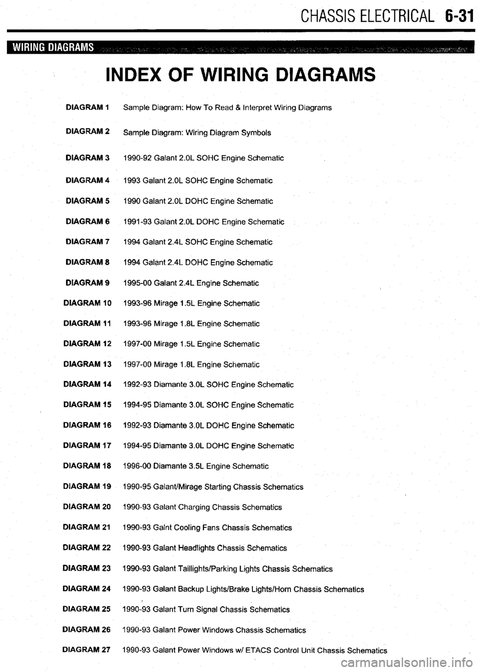
CHASSIS ELECTRICAL 6-31
INDEX OF WIRING DIAGRAMS
DIAGRAM 1 Sample Diagram: How To Read & Interpret Wiring Diagrams
DIAGRAM 2
Sample Diagram: Wiring Diagram Symbols
DIAGRAM 3 1990-92 Galant 2.OL SOHC Engine Schematic
DIAGRAM 4 1993 Galant 2.OL SOHC Engine Schematic
DIAGRAM 5 1990 Galant 2.OL DOHC Engine Schematic
DIAGRAM 6 1991-93 Galant 2.OL DOHC Engine Schematic
DIAGRAM 7 1994 Galant 2.4L SOHC Engine Schematic
DIAGRAM 8 1994 Galant 2.4L DOHC Engine Schematic
DIAGRAM 9
199500 Galant 2.4L Engine Schematic
DIAGRAM 10 1993-96 Mirage 1.5L Engine Schematic
DIAGRAM 11 1993-96 Mirage 1.8L Engine Schematic
DIAGRAM 12 1997-00 Mirage 1.5L Engine Schematic
DIAGRAM 13 1997-00 Mirage 1.8L Engine Schematic
DIAGRAM 14 1992-93 Diamante 3.OL SOHC Engine Schematic
DIAGRAM 15 1994-95 Diamante 3.OL SOHC Engine Schematic
DIAGRAM 16 1992-93 Diamante 3.OL DOHC Engine Schematic
DIAGRAM 17 1994-95 Diamante 3.OL DOHC Engine Schematic
DIAGRAM 18 1996-00 Diamante 35L Engine Schematic
DIAGRAM 19 1990-95 Galant/Mirage Starting Chassis Schematics
DIAGRAM 20 1990-93 Galant Charging Chassis Schematics
DIAGRAM 21 1990-93 Galnt Cooling Fans Chassis Schematics
DIAGRAM 22 1990-93 Galant Headlights Chassis Schematics
DIAGRAM 23 1990-93 Galant Taillights/Parking Lights Chassis Schematics
DIAGRAM 24 1990-93 Galant Backup Lights/Brake Lights/Horn Chassis Schematics
DIAGRAM 25 1990-93 Galant Turn Signal Chassis Schematics
DIAGRAM 26 1990-93 Galant Power Windows Chassis Schematics
DIAGRAM 27 1990-93 Galant Power Windows wl ETACS Control Unit Chassis Schematics
Page 235 of 408
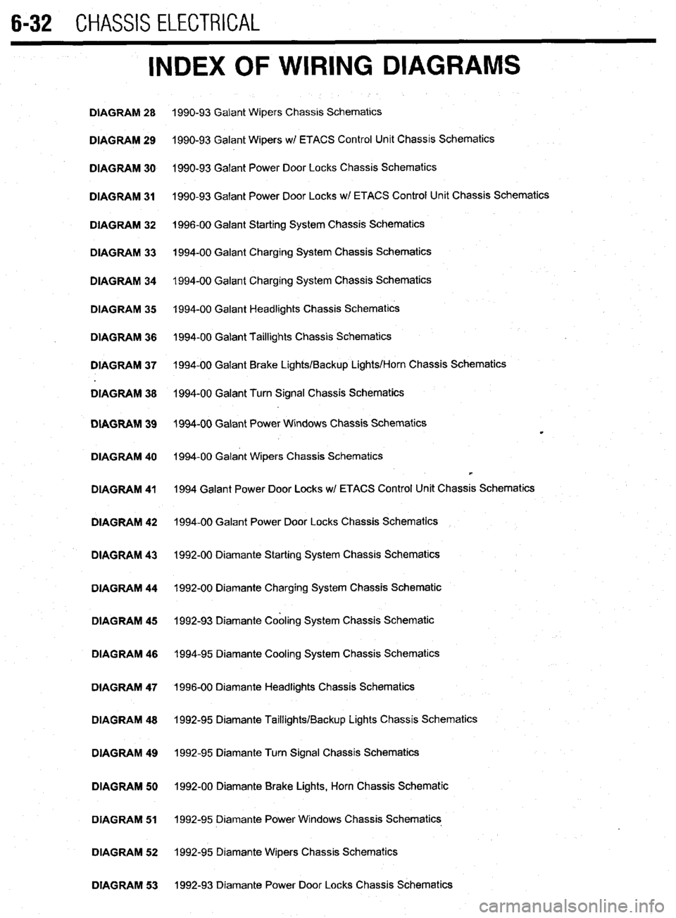
6-32 CHASSIS ELECTRICAL
INDEX OF WIRING DIAGRAMS
DIAGRAM 28 1990-93 Galant Wipers Chassis Schematics
DIAGRAM 29 1990-93 Galant Wipers w/ ETACS Control Unit Chassis Schematics
DIAGRAM 30 1990-93 Galant Power Door Locks Chassis Schematics
DIAGRAM 31 1990-93 Galant Power Door Locks wl ETACS Control Unit Chassis Schematics
DIAGRAM 32 1996-00 Galant Starting System Chassis Schematics
DIAGRAM 33 1994-00 Galant Charging System Chassis Schematics
DIAGRAM 34 1994-00 Galant Charging System Chassis Schematics
DIAGRAM 35 1994-00 Galant Headlights Chassis Schematics
DIAGRAM 36 1994-00 Galant Taillights Chassis Schematics
DIAGRAM 37 1994-00 Galant Brake Lights/Backup Lights/Horn Chassis Schematics
DIAGRAM 38 1994-00 Galant Turn Signal Chassis Schematics
DIAGRAM 39 1994-00 Galant Power Windows Chassis Schematics
m
DIAGRAM 40 1994-00 Galant Wipers Chassis Schematics
b
DIAGRAM 41 1994 Galant Power Door Locks w/ ETACS Control Unit Chassis Schematics
DIAGRAM 42 1994-00 Galant Power Door Locks Chassis Schematics
DIAGRAM 43 1992-00 Diamante Starting System Chassis Schematics
DIAGRAM 44 1992-00 Diamante Charging System Chassis Schematic
DIAGRAM 45 1992-93 Diamante Cabling System Chassis Schematic
DIAGRAM 46 1994-95 Diamante Cooling System Chassis Schematics
DIAGRAM 47 1996-00 Diamante Headlights Chassis Schematics
DIAGRAM 48 1992-95 Diamante Taillights/Backup Lights Chassis Schematics
DIAGRAM 49 1992-95 Diamante Turn Signal Chassis Schematics
DIAGRAM 50 1992-00 Diamante Brake Lights, Horn Chassis Schematic
DIAGRAM 51 1992-95 Diamante Power Windows Chassis Schematics
DIAGRAM 52 1992-95 Diamante Wipers Chassis Schematics
DIAGRAM 53 1992-93 Diamante Power Door Locks Chassis Schematics
Page 236 of 408
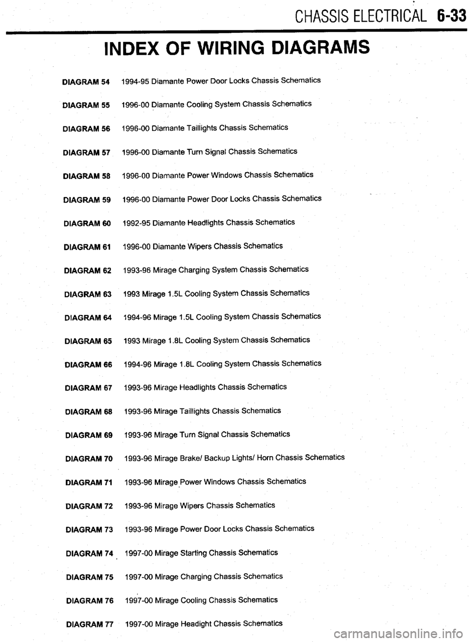
CHASSIS ELECTRlCiL 6-33
INDEX OF WIRING DIAGRAMS
DIAGRAM 54
DIAGRAM 55
DIAGRAM 56
DIAGRAM 57
DIAGRAM 58
DIAGRAM 59
DIAGRAM 60
DIAGRAM 61
DIAGRAM 62
DIAGRAM 63
DIAGRAM 64
DIAGRAM 65
DIAGRAM 66
DIAGRAM 67
DIAGRAM 68
DIAGRAM 69
DIAGRAM 70
DIAGRAM 71
DIAGRAM 72
DIAGRAM 73
DIAGRAM 74
DIAGRAM 75
DIAGRAM 76
DIAGRAM 77 1994-95 Diamante Power Door Locks Chassis Schematics
1996-00 Diamante Cooling System Chassis Schematics
1996-00 Diamante Taillights Chassis Schematics
1996-00 Diamante Turn Signal Chassis Schematics
1996-00 Diamante Power Windows Chassis Schematics
1996-00 Diamante Power Door Locks Chassis Schematics
1992-95 Diamante Headlights Chassis Schematics
1996-00 Diamante Wipers Chassis Schematics
1993-96 Mirage Charging System Chassis Schematics
1993 Mirage 1.5L Cooling System Chassis Schematics
1994-96 Mirage 1.5L Cooling System Chassis Schematics
1993 Mirage 1.8L Cooling System Chassis Schematics
1994-96 Mirage 1.8L Cooling System Chassis Schematics
1993-96 Mirage Headlights Chassis Schematics
1993-96 Mirage Taillights Chassis Schematics
1993-96 Mirage Turn Signal Chassis Schematics
1993-96 Mirage Brake/ Backup Lights/ Horn Chassis Schematics
1993-98 Mirage-Power Windows Chassis Schematics
1993-96 Mirage Wipers Chassis Schematics
1993-96 Mirage Power Door Locks Chassis Schematics
1997-00 Mirage Starting Chassis Schematics
1997-00 Mirage Charging Chassis Schematics
1997-00 Mirage Cooling Chassis Schematics
1997-00 Mirage Headight Chassis Schematics