1900 MITSUBISHI DIAMANTE washer fluid
[x] Cancel search: washer fluidPage 10 of 408
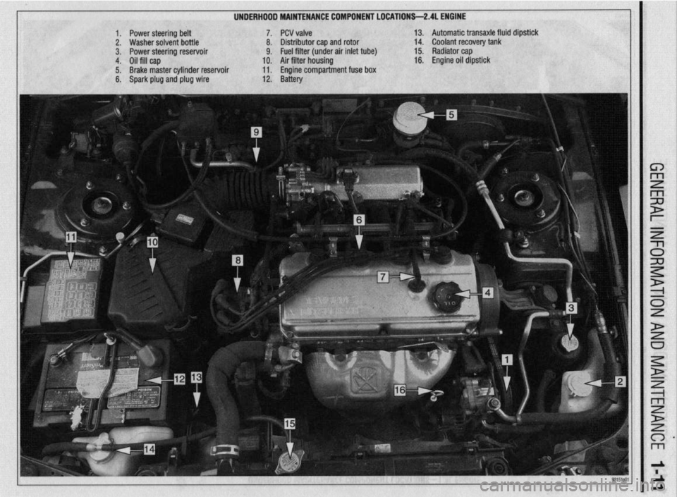
UNDERHDDD MAINTENANCE COMPONENT LOCATIONS-2AL ENGINE
II
1. Power steering belt 7. PCV valve
2. Washer solvent bottle 8. Distributor cap and rotor
3. Power steering reservoir 9. Fuel filter (under air inlet tube)
4. Oil fill cap 10. Air filter housing
5. Brake master cylinder reservoir 11. Engine compartment fuse box
6. Spark plug and plug wire 12. Battery 13. Automatic transaxle fluid dipstick
14. Coolant recovery tank
15. Radiator cap
16. Engine oil dipstick
Page 11 of 408
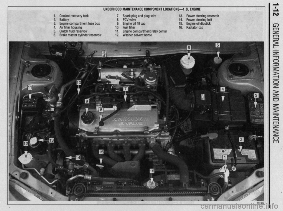
UNDERHOOD MAINTENANCE COMPONENT LOCATIONS-l .8L ENGINE
1. Coolant recovery tank
2. Battery
3. Engine compartment fuse box
4. Air filter housing
5. Clutch fluid reservoir
6. Brake master cylinder reservoir 7. Spark plug and plug wire
8. PCV valve
9. Engine oil fill cap
10. Fuel filter
11. Engine compartment relay center
12. Washer solvent bottle 13. Power steering reservoir
14. Power steering belt
15. Engine oil dipstick
16. Radiator cap
Page 42 of 408
GENERALINFORMATIONAND MAINTENANCE l-43
l Special car washing detergent is the best to
use. Liquid dishwashing detergent can remove wax
and leave the car’s paint unprotected and in addition
some liquid detergents contains abrasives which can
scratch the paint.
l Bird droppings should be removed from the
paintwork as soon as possible, otherwise the finish
may be permanently stained.
When the car is driven immediately after be-
ing washed, apply the brakes several times
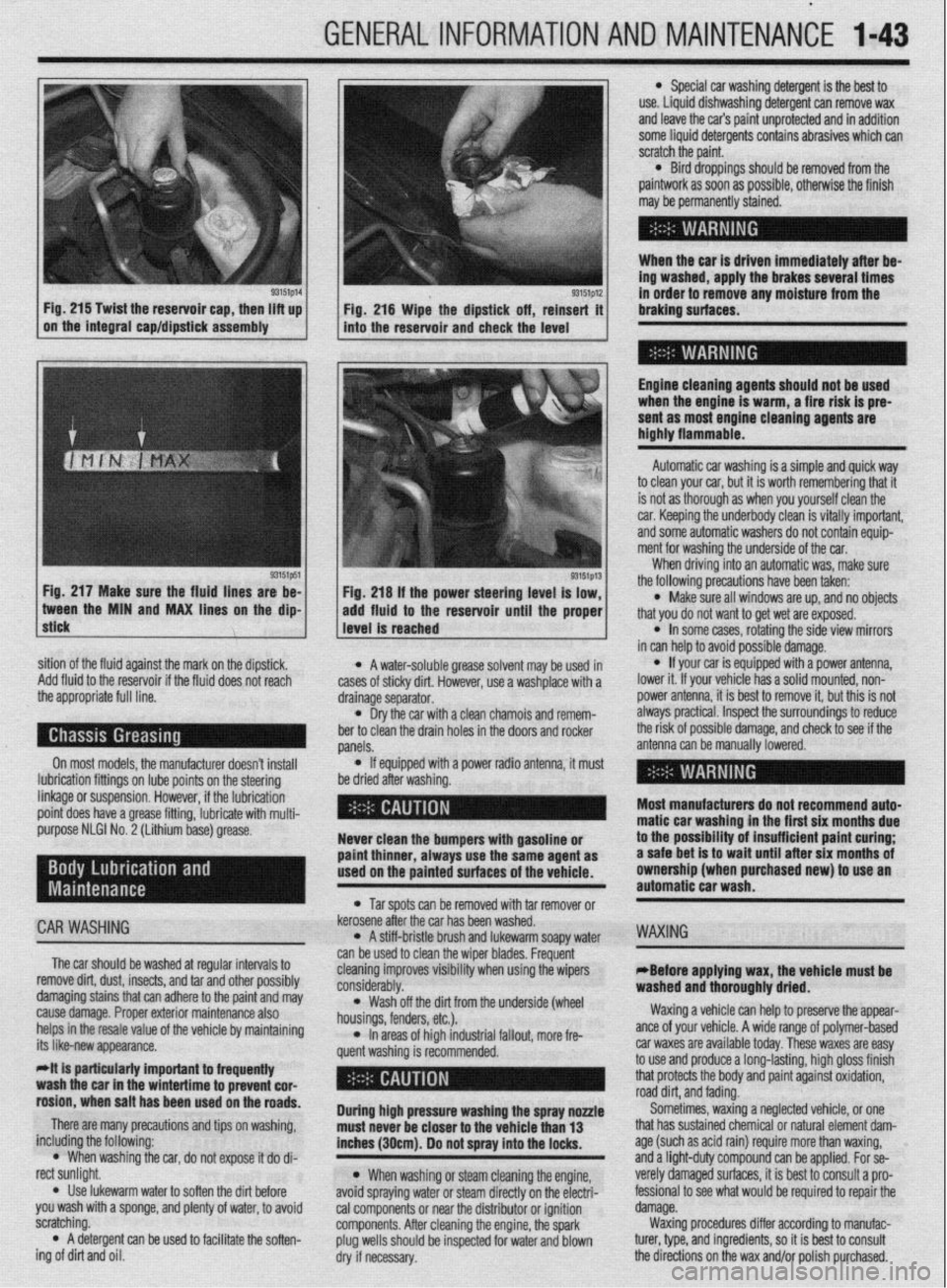
93151p14 93151p12 Fig. 215 Twist the reservoir cap, then lift up
I I
in order to remove any moisture from the
Fig. 216 Wipe the dipstick off, reinsert it braking surfaces.
on the integral cap/dipstick assembly
into the reservoir and check the level
I
Engine cleaning agents should not be used
when the engine is warm, a fire risk is pre-
sent as most engine cleaning agents are
highly flammable.
sition of the fluid against the mark on the dipstick,
Add fluid to the reservoir if the fluid does not reach
the appropriate full line.
On most models, the manufacturer doesn’t install
lubrication fittings on lube points on the steering
linkage or suspension. However, if the lubrication
point does have a grease fitting, lubricate with multi-
purpose NLGI No. 2 (Lithium base) grease.
CAR WASHING
The car should be washed at regular intervals to
remove dirt, dust, insects, and tar and other possibly
damaging stains that can adhere to the paint and may
cause damage. Proper exterior maintenance also
helps in the resale value of the vehicle by maintaining
its like-new appearance.
Mt is particularly important ta frequentiy
wash the car in the wintertime to prevent cor-
rosion, when salt has been used on the roads.
There are many precautions and tips on washing,
including the following:
l When washing the car, do not expose it do di-
rect sunlight.
. Use lukewarm water to soften the dirt before
you wash with a sponge, and plenty of water, to avoid
scratching.
l A detergent can be used to facilitate the soften-
ing of dirt and oil. * A water-soluble grease solvent may be used in
cases of sticky dirt. However, use a washplace with a
drainage separator.
l Dry the car with a clean chamois and remem-
ber to clean the drain holes in the doors and rocker
panels.
l If equipped with a power radio antenna, it must
be dried after washing.
Never clean the bumpers with gasoline or
paint thinner, always use the same agent as
used on the painted surfaces of the vehicle.
l Tar spots can be removed with tar remover or
kerosene after the car has been washed.
l A stiff-bristle brush and lukewarm soapy water
can be used to clean the wiper blades. Frequent
cleaning improves visibility when using the wipers
considerably.
l Wash off the did from the underside (wheel
housings, fenders, etc.).
l In areas of high industrial fallout, more fre-
quent washing is recommended.
During high pressure washing the spray nonle
must never be closer to the vehicle than 13
inches (30cm). Do not spray into the locks.
l When washing or steam cleaning the engine,
avoid spraying water or steam directly on the electri-
cal components or near the distributor or ignition
components. After cleaning the engine, the spark
plug wells should be inspected for water and blown
dry if necessary. Automatic car washing is a simple and quick way
to clean your car, but it is worth remembering that it
is not as thorough as when you yourself clean the
car. Keeping the underbody clean is vitally important,
and some automatic washers do not contain equip-
ment for washing the underside of the car.
When driving into an automatic was, make sure
the following precautions have been taken:
l Make sure all windows are up, and no objects
that you do not want to get wet are exposed.
l In some cases, rotating the side view mirrors
in can help to avoid possible damage.
l If your car is equipped with a power antenna,
lower it. If your vehicle has a solid mounted, non-
power antenna, it is best to remove it, but this is not
always practical. Inspect the surroundings to reduce
the risk of possible damage, and check to see if the
antenna can be manually lowered.
Most manufacturers do not recommend auto-
matic car washing in the first six months due
to the possibility of insufficient paint curing;
a safe bet is to wait until after six months of
ownership (when purchased new) to use an
automatic car wash.
WAXING
eBefore applying wax, the vehicle must be
washed and thoroughly dried.
Waxing a vehicle can help to preserve the appear-
ante of your vehicle. A wide range of polymer-based
car waxes are available today. These waxes are easy
to use and produce a long-lasting, high gloss finish
that protects the body and paint against oxidation,
road dirt, and fading.
Sometimes, waxing a neglected vehicle, or one
that has sustained chemical or natural element dam-
age (such as acid rain) require more than waxing,
and a light-duty compound can be applied. For se-
verely damaged surfaces, it is best to consult a pro-
fessional to see what would be required to repair the
damage.
Waxing procedures differ according to manufac-
turer, type, and ingredients, so it is best to consult
the directions on the wax and/or polish purchased.
Page 220 of 408
CHASSIS ELECTRICAL 647
3. Remove the windshield wiper arms by un-
screwing the cap nuts and lifting the arms from the
linkage posts.
4. Remove the front deck garnish assembly.
Iver.
xl harness plug from
,I6 #-n\,LIr 5. Remove the air inlet c(
6. Disconnect the electric
the wiper motor.
7. Remove the access ho,, LIVIGil. To install:
5. Install the motor and install the retaining bolts.
6. Install the wiper arm so that the arm is 3.35
inches (85mm) between the measurement points,
when parked. Secure the wiper arm with the retaining
nut.
*Before proceeding, connect the battery and
8. Remove the wiper motor mounting bolts.
9. Detach the motor crank arm from the wiper
linkane and remnve the mntnr
motor has been factory set. Do not remove
them unless necessary. if they must be re-
moved, remove them only after marking their
mounting positions. check the operation of the motor. if satisfae-
tory, disconnect the cable and complete the
installation.
o. WIIIIW LIE Il~&WVt: vatreryoable and recheck
the system for proper operation.
..-
a- - ‘- _ _ _ . _ _ _
*The installation angle of the crank arm and 7. Install the interior trim piece
n II ^_^^^ IAL- -^I-I:..- L-AL--
To install:
10. Install the windshield wiper motor and con-
REMOVAL&INSTALLATION nect the linkage.
I 14. Install the front deck garnish assembly. I. YIV”“I1IIYVL VI” “UyuL’.” “UL’“‘, UUUIU. 2. Remove the windshield washer fluid resarvnir
’ 11. Attach the electrical harness plug.
12. Install the access hole cover.
13. Install the air inlet cover.
15. Reinstall the wiper arm and tighten the
mounting nuts to 14 ft. Ibs. (19 Nm). Install the arms
so the blades are parallel to the garnish molding -
Front and Rear
1 nivnnnprt the nonatiua haltorv rahlo
3. Drain any washer fluid in the reservoir into an
appropriate container.
4.
I when parked. Remove the pump from the reservoir by either
16. Connect the neaative batterv cable and check removing the retaining hardware or twisting gently
tlntil it is frpp frnm thP rosorvnir the wiper system for proper operation.
lo Install:
5. Inspect the pump seal on the reservoir, replace
/ de&h the linkage Fig 59 Pull the motor from the firewaii and
“‘%‘y 1 ““I”“,,,,,, the if necessary.
1 1 Disconn& thP rwnativo hatton/ rahlm 6. Install the pump into place until seated on the .I,” ~‘“p.L’,” YULL”‘, -YI”. liftgate lower trim. seal.
3: Lift the smatr CUVBI, I~IIIUV~ tilt: lfAdllllll~ IIUL II --. .-- -^- ^..^ .L^ -_,_:..:-- -.A 7. Install the windshield washer fluid reservoir. 2. Matchmark the wirier arms tn the shaft and A Refill thp wxhpr fllk-l rpqprvnir markthe arms to the proper side for reinstallation and remove the wiper arm.
4. Remove the mountina bolts and remove the “. .,“...S .V.” ....“III. ,*..*” IYUY..“m,.
9. Connect the negative battery cable.
REMOVAL&INSTALLATION
tie interior, release the lock by turning the tie interior, release the lock by turning the
adapter to the right or left and remove the adapter to the rigM or left and remove the
adapter. adapter.
5. The installation is the reverse of the removal
6. The installation is the reverse of the removal
Mirage
1. Disconnect the negative battery cable. Remove
the center trim panel. procedure. Use care not to damage the printed circuit procedure. Use care not to damage the printed circuit
board or any gauge components.
board or any gauge components.
6. Connect the negative battery cable and check
7. Connect the negative battery cable and check
all cluster-related items for proper operation. i III cluster-related items for proper operation.
2. Remove the knee protector. If pin type clips are
used, they may be removed using the following pro-
cedure:
a. Press down on the center pin with a suit-
able blunt pointed tool. Press down a little more
than ‘IIS in. (2mm). This releases the clip. Pull
the clip outward to remove it.
b. Do not push the pin inward more than
necessary because it may damage the grommet
or the pin may fall in, if pushed in too far. Once
the clips are removed, use a plastic trim stick if
necessary to pry the knee protector loose.
3. Remove the instrument cluster bezel.
4. Remove the instrument cluster. Disassemble
and remove gauges or the speedometer as required.
*if the speedometer cable adapter requires
setvice, disconnect the cable at the transaxie
end. Pull the cable slightly toward the vehi- Gaiant
@ See Figures Bg thru 66
1. Disconnect negative battery cable.
2. Remove the 2 retainer screws from the lower
surface of the meter hood.
3. Remove the retainer screws from the underside
top portion of the meter hood.
4. Carefully remove the meter hood from the face
of the combination meter.
5. Remove the 4 retainer screws and the combi-
nation meter assembly with the bezel attached. Re-
move the front bezel and remove gauges or the
speedometer as required.
*if the speedometer cable adapter requires
service, disconnect the cable at the transaxie
end. Pull the cable slightly toward the vehi-
Page 224 of 408
CHASSIS ELECTRICAL 6-21
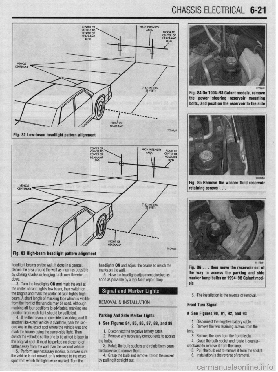
Fig. 82 low-beam headlight pattern alignment
93156pE.3 Fig. 85 Remove the washer fluid reservoir
retaining screws . . .
Fig. 83 High-beam headlight pattern alignment
headlight beams on the wall. If done in a garage,
darken the area around the wall as much as possible
by closing shades or hanging cloth over the win-
dows.
3. Turn the headlights ON and markthe wall at
the center of each light’s low br ram, then switch on
the brights and mark the center of each lights high
beam. A short length of maskin g tape which is visible
from the front of the
whir+ ma . ._..._._ . .._ y be used. Although
marking all four po:
sitions is advisable, marking one
position from each
light should be sufficient.
4. If neithar he; ~. __
Irn on one side is working, and if
another like-sized vehicle is available, park the sec-
nnri nm in the wart cnnt whrw the whirlo um md
headli! jhts ON and adjust the beams to marcn me
I. Disconnect the negative battery cable. marks on the wall.
2. Remove any necessary components to access 6.
the bulbs. Have the headlight adjustment checked as
soon as possible by a reputable repair shop.
3. Rotate the bulb sockets and rotate them coun-
terclockwise to remove them.
4. Grasp the bulb and remove it from the socket REMOVAL&INSTALLATION
Parking And Side Marker Lights
p See Figures 84, 85, 88, 87, 88, and 89 !ss the parking and side
1~ nn loo4-98 Galant mod-
I
1 I-
5315@61
lens. 1 Fio. 8
then move the reservoir out of
3. Remove the lens from the front fascia.
4. Grasp the bulb socket and rotate it counter- marker lamp bult, _.. ._“~-
clockwise to remove it from the lamp.
5. Pull the bulb out to remove it from the socket. 5. The installation is the reverse of removal.
6. Installation is the reverse of removal. Front turn Signal
p See Figures 91
1. Disconnect tl
2. Remove the t 0, 91, 92, and 93
I(? n,-.nn+:.m b.Hnn, nnL.L
z Ill7yau”e “allcly ul”IC. 10 retainino screws from the
spot from which the lights were marked. Turn the . ..I_ WIIY I.8 %,I” V”UVL”fdYI T.II”IU Lll” “VlllUlY ,.UU U,,” mark the beams using the same-side light. Then
switch the vehicles so the one to be aimed is back in
the original spot. It must be parked no closer to or
farther away from the wall than the second vehicle.
5. Perform any necessary repairs, but make sure
the vehicle is not moved, or is returned to the exact
by pulling it straight out.
Page 288 of 408
DRIVETRAIN 7-9
*When adjusting the clutch pedal height or
the clutch pedal clevis pin play, be careful
not to push the pushrod toward the master
cylinder.
d. Check that when the clutch pedal is de-
pressed all the way, the interlock switch switches
over from ON to OFF.
ADJUSTMENT
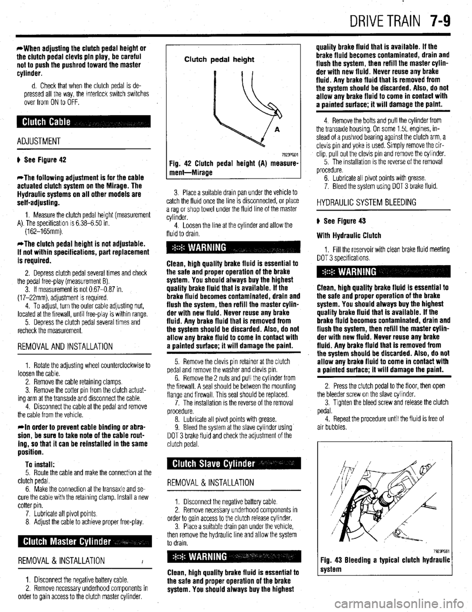
# See Figure 42
*The following adjustment is for the cable
actuated clutch system on the Mirage. The
Hydraulic systems on all other models are
self-adjusting.
1. Measure the clutch pedal height (measurement
A). The specificatron is 6.38-6.50 in.
(162-165mm).
*The clutch pedal height is not adjustable.
If not within specifications, part replacement
is required.
2. Depress clutch pedal several times and check
the pedal free-play (measurement B).
3. If measurement is not 0.67-0.87 in.
(17-22mm), adjustment is required.
4. To adjust, turn the outer cable adjusting nut,
located at the firewall, until free-play is within range.
5. Depress the clutch pedal several times and
recheck the measurement.
REMOVALANDINSTALLATION
1. Rotate the adjusting wheel counterclockwise to
loosen the cable.
2. Remove the cable retaining clamps.
3. Remove the cotter pin from the clutch actuat-
ing arm at the transaxle and disconnect the cable.
4. Disconnect the cable at the pedal and remove
the cable from the vehicle.
rln order to prevent cable binding or abra-
sion, be sure to take note of the cable rout-
ing, so that it can be reinstalled in the same
position.
To install:
5. Route the cable and make the connection at the
clutch pedal.
6. Make the connection at the transaxle and se-
cure the cable with the retaining clamp. Install a new
cotter pin.
7. Lubricate all pivot points.
8 Adjust the cable to achieve proper free-play.
REMOVAL &INSTALLATION
I
1. Disconnect the negative battery cable.
2. Remove necessary underhood components in
order to gain access to the clutch master cylinder.
Clutch pedal height
Fig. 42 Clutch pedal height (A) measure-
ment-Mirage
7923PGDl
3. Place a suitable drain pan under the vehicle to
catch the fluid once the line IS drsconnected, or place
a rag or shop towel under the fluid line of the master
cylinder.
4. Loosen the line at the cylinder and allow the
fluid to drain.
Clean, high quality brake fluid is essential to
the safe and proper operation of the brake
system. You should always buy the highest
quality brake fluid that is available. If the
brake fluid becomes contaminated, drain and
flush the system, then refill the master cylin-
der with new fluid. Never reuse any brake
fluid. Any brake fluid that is removed from
the system should be discarded. Also, do not
allow any brake fluid to come in contact with
a oainted surface; it will damage the paint.
5. Remove the clevis pin retainer at the clutch
pedal and remove the washer and clevis pm.
6. Remove the 2 nuts and pull the cylinder from
the firewall. A seal should be between the mounting
flange and firewall. This seal should be replaced.
7. The installation is the reverse of the removal
procedure.
8. Lubricate all pivot points with grease.
9. Bleed the system at the slave cylinder using
DOT 3 brake fluid and check the adjustment of the
clutch pedal.
REMOVAL &INSTALLATION
1. Disconnect the negative battery cable
2. Remove necessary underhood components in
order to gain access to the clutch release cylinder.
3. Place a suitable drain pan under the vehicle,
then remove the hydraulic line and allow the system
to drain.
Clean, high quality brake fluid is essential to
the safe and proper operation of the brake
system. You should always buy the highest quality brake fluid that is available. If the
brake fluid becomes contaminated, drain and
flush the system, then refill the master cylin-
der with new fluid. Never reuse any brake
fluid. Any brake fluid that is removed from
the system should be discarded. Also, do not
allow any brake fluid to come in contact with
a uainted surface; it will damage the paint.
4. Remove the bolts and pull the cylinder from
the transaxle housing. On some 1.5L engines, in-
stead of a pushrod bearing against the clutch arm, a
clevis pin and yoke is used. Simply remove the cir-
clip, pull out the clevis pin and remove the cylinder.
5. The installation IS the reverse of the removal
procedure.
6. Lubricate all pivot points with grease.
7. Bleed the system using DOT 3 brake fluid.
HYDRAULIC SYSTEM BLEEDING
) See Figure 43
With Hydraulic Clutch
1, Fill the reservoir with clean brake fluid meeting
DOT 3 specificatrons.
Clean, high quality brake fluid is essential to
the safe and proper operation of the brake
system. You should always buy the highest
quality brake fluid that is available. If the
brake fluid becomes contaminated, drain and
flush the system, then refill the master cylin-
der with new fluid. Never reuse any brake
fluid. Any brake fluid that is removed from
the system should be discarded. Also, do not
allow any brake fluid to come in contact with
a painted surface; it will damage the paint.
2. Press the clutch pedal to the floor, then open
the bleeder screw on the slave cvlinder.
3. Tighten the bleed screw and release the clutch
pedal.
4. Repeat the procedure until the fluid is free of
air bubbles.
7923PG91 Fig. 43 Bleeding a typical clutch hydraulic
system
Page 294 of 408
DRIVETRAiN 7-15
MATING MARKS
/
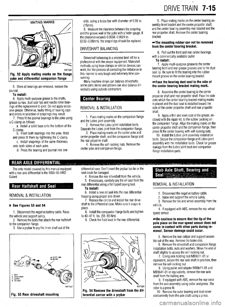
89577Q5E Fig. 52 Apply mating marks on the flange
yoke and differential companion flange
5. Once all bearings are removed, remove the
journal.
To install:
6. Apply multi-purpose grease to the shafts,
grease sumps, dust seal lips and needle roller bear-
ings of the replacement U-joint Do not apply exces-
sive grease Otherwse, faulty fitting of bearing caps
and errors in selection of snaprings may result.
7. Press fit the journal bearings to the yoke using
a C-clamp as follows:
a. Install a solid base onto the bottom of the
C-clamp.
b. Insert both bearings into the yoke. Hold
and press fit them by tightening the C-clamp.
c. Install snaprings of the same thickness
onto both sides of each yoke.
d. Press the bearing and journal into one side, using a brass bar with diameter of 0.59 in.
(15mm).
8. Measure the clearance between the snapring
and the groove wall of the yoke with a feeler gauge. If
the clearance exceeds 0.0008-0.0024 in.
(0.02-O.O6mm), the snap rings should be replaced.
DRIVESHAFT BALANCING
Driveshaft balancing is a process best left for a
professional wrth the proper equipment. Makeshift
methods using hose clamps or similar devices can
work, but the process of correcting the imbalance in
this manner is very tough and extremely time con-
suming.
Many machine shops can balance driveshafts;
some parts stores and jobbers can also balance dri-
veshafts using outside contractors.
REMOVAL&INSTALLATION
1. Place matmg marks on the companron flange
and the Lobro joint assembly
2. Remove the Lobro joint installation bolts.
Separate the Lobro joint from the companion flange.
3. Place mating marks on the center yoke and
center propeller shaft, and the companion flange and
the rear propeller shaft.
4. Remove the self-locking nuts. Remove the
center yoke and companion flange. 5. Place mating marks on the center bearing as-
sembly front bracket and the center propeller shaft,
and the center bearing assembly rear bracket and the
rear propeller shaft. Remove the center bearing
bracket.
*The mounting rubber can not be removed
from the center bearing bracket.
6. Pull out the front and rear center bearings
with a commercially available puller
To install:
7. Apply multi-purpose grease to the center
bearing front and rear grease grooves and to the dust
seal lip Be sure to fit the bearing into the rubber
mount groove on the center bearing bracket.
*Face the bearing dust seal to the side of
the center bearing bracket mating mark.
8. Assemble the center bearing to the center
propeller shaft and rear propeller shaft. Face the side
onto which the center bearing bracket mating marks
IS placed and the dust seal is installed toward the
side of the center propeller shaft and rear propeller
shaft.
9 Apply a thin and even coat of the grease, en-
closed with the repair kit, to the rubber packing on
the companion flange. Align the mating marks on the
center propeller shaft and the companion flange, then
press fit the center bearing with self-locking nuts.
10 Install the Lobro joint assembly installation
bolts. Secure the companron flange and Lobro joint
assembly with the installation bolts Check for grease
leakage from the Lobro joint boot and companion
flange installabon parts.
The only model covered by this manual equipped
with a rear axle differential is the 1990-93 AWD
Galant.
REMOVAL &INSTALLATION
# See Figures 53 and 54
1. Disconnect the negative battery cable. Raise
the vehicle and support safely.
2. Remove the bolts that attach the rear halfshaft
to the comoanion flanae.
3. Use’a prybar topry the inner shaft out of the
I Fig. 53 Rear driveshaft mounting
89577g5
differential case. Don’t insert the prybar too far or the
seal could be damaged.
4 Remove the rear driveshaft from the vehicle.
5. If necessary, carefully pry the oil seal from the
rear differential using a flat tipped prying tool.
To install:
6. Install a new oil seal into the rear differential
housing using proper size driver.
7. Replace the circlip and install the rear drive-
shaft to the differential case. Make sure it snaps in
place.
8. Install the companion flange bolts and tighten
to 40-47 ft. Ibs. (55-65 Nm).
9. Check the fluid level in the rear differential.
69577958 Fig. 54 Remove the driveshaft from the dif-
ferential carrier with a prybar
REMOVAL &INSTALLATION
1. Disconnect the negative battery cable.
2. Raise and support the vehicle safely.
3 Remove the tire and wheel assembly from the
vehicle.
4 If equipped with ABS, remove the rear wheel
speed sensor.
*Be cautious to ensure that the tip of the
pole piece on the rear speed sensor does not
come in contact with other parts during re-
moval. Sensor damage could occur.
5. Remove the rear caliper and support assem-
bly out of the way. Remove the brake disc.
6. Remove the driveshaft and companion flange
installation bolts, nuts and washers. Move the end of
shaft slightly to access the self-locking nut.
7. Using axle holding tool MBSbll-01 or
equivalent, secure the rear axle shaft in position, then
remove the self-locking nut.
8. Using puller and adapter MBSbll-01 and
MB9b41-01 or equivalents, remove the rear axle
shaft from the trailing arm
9. If equipped with ABS, remove the rear rotor
from the axle assembly using collar and press. The
rotor is a press fit.
10 Remove the outer bearing and dust cover
concurrently from the axle shaft using a press.
Page 334 of 408
- 8-38 SUSPENSION AND STEERING
11. Adjust the power steering belt for proper ten-
sion and tighten the adjusting bolts.
12. Reconnect the negative battery cable.
13. Refill the reservoir and bleed the system.
3. Of EIJGINE
1. Disconnect the battery negative cable. 2. Disconnect the return fluid line. Remove the
reservoir cap and allow the return line to drain the
fluid from the reservoir. If the fluid is contaminated,
disconnect the ignition high tension cable and crank
the engine several times to drain the fluid from the
gear box.
3. Remove the power steering pump drive belt.
4. Remove the pressure switch connector from
the side of the pump.
5. If the alternator is located under the oil pump,
cover it with a shop towel to protect it from oil.
6. Disconnect the high pressure hose and the
return hose from the pump.
7. Remove the pump drive belt and unbolt the
pump from its bracket and remove the pump.
To install: 8. Install the pump, *rap the belt around the
pulley and tighten the bolts that secure the pump to
17 ft. Ibs. (24 Nm).
9. Replace the O-rings and connect the high
pressure hose. Connect the pressure line so the
notch in the fitting aligns and contacts the pump’s
guide bracket. Tighten the mounting nut with lock-
washer to 17 ft. Ibs. (24 Nm).
IO. Using a new hose clamp, connect the return
line.
11. Attach the pressure switch connector.
12. Adjust the belt tension and tighten the
adjust- ing bolts.
13. Refill the reservoir and bleed the system.
Diamante *
FRONT
. 1. Disconnect the battery negative cable. 2. Disconnect the return fluid line. Remove the
reservoir cap and allow the return line to drain the
fluid from the reservoir. If the fluid is contaminated,
disconnect the ignition high tension cable and crank
the engine several times to drain the fluid from the
gearbox.
3. Remove the power steering pump drive belt.
4. Remove the pressure switch connector from
the side of the pump.
5. If the alternator is located under the oil pump,
cover it with a shop towel to protect it from oil.
6. Disconnect the high pressure hose and the
return hose from the pump.
7. Remove the pump drive belt and unbolt the
pump from its bracket and remove the pump.
To install: 8. Install the pump, wrap the belt around the
pulley and tighten the bolts that secure the pump to
17 ft. Ibs. (24 Nm).
9. Replace the O-rings and connect the high
pressure hose. Connect the pressure line so the
notch in the fitting aligns and contacts the pump’s
guide bracket. Tighten the mounting nut with lock-
washer to 17 ft. Ibs. (24 Nm).
10. Using a new hose clamp, connect the return
line.
Il. Attach the pressure switch connector.
12. Adjust the belt tension and tighten the adjust-
ing bolts.
13. Refill the reservoir and bleed the system.
REAR
1. Disconnect the negative battery cable.
2. Drain the power steering fluid.
3. Remove the rear power steering pump heat
protector, located on the engine side of the differen-
tial on the transaxle.
4. Disconnect the pressure line from the pump.
5. Disconnect the suction hose from the pump.
6. Remove the mounting bolts and remove the
pump from the transaxle.
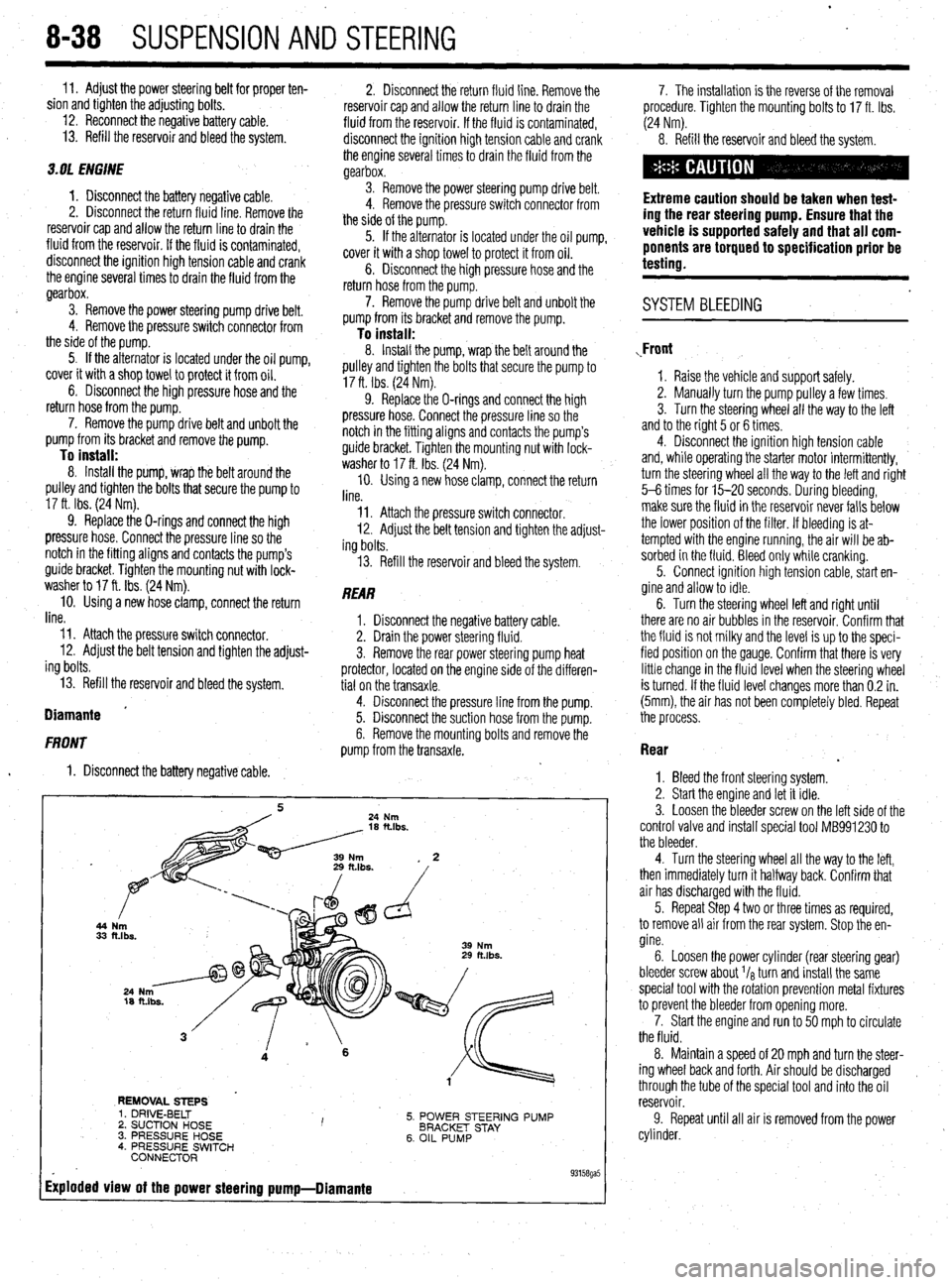
44
33
REMOVAL STEPS
5. POWER STEERING PUMP
BRACKET STAY
6. OIL PUMP 1. DRIVE-BELT
2. SUCTION HOSE I ’ 3. PRESSURE HOSE
4. PRESSURE SWITCH
CONNECTOR
Exploded view of the power steering pump-Diamante
. 93158ga5
7. The installation is the reverse of the removal
procedure. Tighten the mounting bolts to 17 ft. Ibs.
(24 Nm).
8. Refill the reservoir and bleed the system.
Extreme caution should be taken when test-
ing the rear steering pump. Ensure that the
vehicle is supported safely and that all com-
ponents are torqued to specification prior be
testing.
. SYSTEM BLEEDING
,Front
1. Raise the vehicle and support safely.
2. Manually turn the pump pulley a few times.
3. Turn the steering wheel all the way to the left
and to the right 5 or 6 times.
4. Disconnect the ignition high tension cable
and, while operating the starter motor intermittently,
turn the steering wheel all the way to the letI and right
5-6 times for 15-20 seconds. During bleeding,
make sure the fluid in the reservoir never falls below
the lower position of the filter. If bleeding is at-
tempted with the engine running, the air will be ab-
sorbed in the fluid. Bleed only while cranking.
5. Connect ignition high tension cable, start en-
gine and allow to idle.
6. Turn the steering wheel left and right until
there are no air bubbles in the reservoir. Confirm that
the fluid is not milky and the level is up to the speci-
fied position on the gauge. Confirm that there is very
little change in the fluid level when the steering wheel
is turned. If the fluid level changes more than 0.2 in.
(5mm), the air has not been completely bled. Repeat
the process.
Rear
.
1. Bleed the front steering system.
2. Start the engine and let it idle.
3. Loosen the bleeder screw on the left side of the
control valve and install special tool MB991230 to
the bleeder.
4. Turn the steering wheel all the way to the left,
then immediately turn it halfway back. Confirm that
air has discharged with the fluid.
5. Repeat Step 4 two or three times as required,
to remove all air from the rear system. Stop the en-
gine.
6. Loosen the power cylinder (rear steering gear)
bleeder screw about I/* turn and install the same
special tool with the rotation prevention metal fixtures
to prevent the bleeder from opening more.
7. Start the engine and run to 50 mph to circulate
the fluid.
8. Maintain a speed of 20 mph and turn the steer-
ing wheel back and forth. Air should be discharged ,
through the tube of the special tool and into the oil
reservoir.
9. Repeat until all air is removed from the power
cylinder.