1900 MITSUBISHI DIAMANTE differential
[x] Cancel search: differentialPage 2 of 408
.
1-2 GENERALINFORMATIONAND MAINTENANCE
Chitton’s Total Car Care manual for the 199M10
Mitsubishi Mirage, Galant and Diamante is intended
to help you learn more about the inner workings of
your vehicle while saving you money on its upkeep
and operation.
The beginning of the book will likely be referred to
the most, since that is where you will find information
for maintenance and tune-up. The other sections deal
with the more complex systems of your vehicle. Oper-
ating systems from engine through brakes are cov-
ered to the extent that the average do-it-yourselfer be-
comes mechanically involved. This book will not
explain such things as rebuilding a differential for the
simple reason that the expertise required and the in-
vestment in special tools make this task uneconomi-
cal. It will, however, give you detailed instructions to
help you change your own brake pads and shoes, re-
place spark plugs, and perform many more jobs that
can save you money, give you personal satisfaction
and help you avoid expensive problems.
A secondary purpose of this book is a reference for
owners who want to understand their vehicle and/or
their mechanics better. In this case, no tools at all are
required.
Before removing any bolts, read through the entire
procedure. This will give you the overall view of what
tools and supplies will be required. There is nothing
more frustrating than having to walk to the bus stop
on Monday morning because you were short one bolt
on Sunday afternoon. So read ahead and plan ahead.
Each operation should be approached logically and
all procedures thoroughly understood before attempt-
ing any work.
All sections contain adjustments, maintenance, re-
moval and installation procedures, and in some cases,
repair or overhaul procedures. When repair is not con-
sidered practical, we tell you how to remove the part
and then how to install the new or rebuilt replacement.
In this way, you at least save labor costs. “Backyard”
repair of some components is just not practical.
Many procedures in this book require you to “label
and disconnect. . ” a group of lines, hoses or wires.
Don’t be lulled into thinking you can remember where
everything goes-you won’t. If you hook up vacuum
or fuel lines incorrectly, the vehicle may run poorly, if
at all. If you hook up electrical wiring incorrectly, you
may instantly learn a very expensive lesson.
You don’t need to know the official or engineering
name for each hose or line. A piece of masking tape
on the hose and a piece on its fitting will allow you to
assign your own label such as the letter A or a short name. As long as you remember your own code, the
lines can be reconnected by matching similar letters
or names. Do remember that tape will dissolve in
gasolrne or other fluids; if a component is to be
washed or cleaned, use another method of identifica-
tion. A permanent felt-tipped marker or a metal scribe
can be very handy for marking metal parts. Remove
any tape or paper labels after assembly.
It’s necessary to mention the difference between
maintenance and repair Maintenance includes rou-
tine inspections, adjustments, and replacement of
parts which show signs of normal wear Maintenance
compensates for wear or deterioration. Repair implies
that something has broken or is not working. A need
for repair is often caused by lack of maintenance. Ex-
ample, draining and refilling the automatic transaxle
fluid is maintenance recommended by the manufac-
turer at specific mileage intervals. Failure to do this
can shorten the life of the transmission/transaxle, re-
quiring very expensive repairs. While no maintenance
program can prevent items from breaking or wearing
out, a general rule can be stated: MAINTENANCE IS
CHEAPER THAN REPAIR.
Two basic mechanrc’s rules should be mentioned
here. First, whenever the left side of the vehicle or en-
gine is referred to, it is meant to specify the drivers
side. Conversely, the right side of the vehicle means
the passengers side. Second, screws and bolts are
removed by turning counterclockwise, and tightened
by turning clockwrse unless specifically noted.
Safety is always the most important rule. Con-
stantly be aware of the dangers involved in working
on an automobile and take the proper precautions.
See the informatron in this section regarding SER-
VICING YOUR VEHICLE SAFELY and the SAFETY
NOTICE on the acknowledgment page.
Pay attention to the instructions provided. There
are 3 common mistakes in mechanical work:
1. Incorrect order of assembly, disassembly or
adjustment. When taking something apart or putting
it together, performing steps in the wrong order usu-
ally just costs you extra time; however, it CAN break
something. Read the entire procedure before begin-
ning disassembly. Perform everything in the order in
which the instructions say you should, even if you
can’t immedrately see a reason for it. When you’re
taking apart something that is very intricate, you
might want to draw a picture of how it looks when as-
sembled at one point in order to make sure you get everything back in its proper position. We will supply
exploded views whenever possible. When making
adjustments, perform them in the proper order. One
adjustment possibly will affect another.
2. Overtorquing (or undertorquing). While it is
more common for overtorquing to cause damage,
undertorquing may allow a fastener to vibrate loose
causing serious damage. Especially when dealing
with aluminum parts, pay attention to torque specifi-
cations and utilize a torque wrench in assembly. If a
torque figure is not available, remember that if you
are using the right tool to perform the job, you will
probably not have to strain yourself to get a fastener
tight enough. The pitch of most threads is so slight
that the tension you put on the wrench will be multi-
plied many times in actual force on what you are
tightening. A good example of how critical torque is
can be seen in the case of spark plug installation, es-
pecially where you are putting the plug into an alu-
minum cylinder head. Too little torque can fail to
crush the gasket, causing leakage of combustion
gases and consequent overheating of the plug and
engine parts. Too much torque can damage the
threads or distort the plug, changing the spark gap.
There are many commercial products available for
ensuring that fasteners won’t come loose, even if they
are not torqued just right (a very common brand is
Loctite? If you’re worried
about getting something
together tight enough to hold, but loose enough to
avoid mechanical damage during assembly, one of
these products might offer substantial insurance. Be-
fore choosing a threadlocking compound, read the
label on the package and make sure the product is
compatible with the materials, fluids, etc. involved.
3. Crossthreading. This occurs when a part such
as a bolt is screwed into a nut or casting at the wrong
angle and forced. Crossthreading is more likely to
occur if access is difficult. It helps to clean and lubri-
cate fasteners, then to start threading the bolt, spark
plug, etc. with your fingers If you encounter resis-
tance, unscrew the part and start over again at a dif-
ferent angle until it can be inserted and turned several
times without much effort. Keep in mind that many
parts, especially spark plugs, have tapered threads,
so that gentle turning will automatically bring the part
you’re threading to the proper angle. Don’t put a
wrench on the part until its been tightened a couple
of turns by hand. If you suddenly encounter resis-
tance, and the part has not seated fully, don’t force it.
Pull it back out to make sure it’s clean and threading
properly.
Be sure to take your time and be patient, and al-
ways plan ahead. Allow yourself ample time to per-
form repairs and maintenance You may find main-
taining your car a satisfying and enjoyable
experience.
b See Figures 1 thru 15
Naturally, without the proper tools and equipment
it is impossible to properly service your vehicle. It
would also be virtually impossible
to catalog every
tool that you would need to perform all of the opera-
tions in this book. Of course, It would be unwise for
the amateur to rush out and buy an expensive set of
tools on the theory that he/she may need one or more
of them at some time, The best approach is to proceed slowly, gathering savings will
be far outweighed by frustration and
a good quality set of those tools that are used most mangled knuckles.
frequently Don’t be misled by the low cost of bargain Begin accumulating those tools that are used most
tools. It is far better to spend a little more for better frequently: those associated with routine maintenance
quality. Forged wrenches, 6 or 12-point sockets and and tune-up. In addition to the normal assortment of
fine tooth ratchets are by far preferable to their less screwdrivers and pliers, you should have the follow-
expensive counterparts. As any good mechanic can ing tools:
tell you, there are few worse experiences than trying
l Wrenches/sockets and combination open
to work on a vehicle with bad tools. Your monetary end/box end wrenches in sizes from %-% in. or
Page 9 of 408
.
l-10 GENERALINFORMATIONAND MAINTENANCE
which are available today will have two scales so the
The conversion factor chart is used by taking the
Standard or Metric measurements may easily be given specification and multiplying it by the neces-
taken. If any of the various measuring tools which are sary conversion factor. For instance, looking at the
available to you do not contain the same scale as first line, if you have a measurement in inches such
listed in the specifications, use the accompanying
as “free-play should be 2 in.” but your ruler reads
conversion factors to determine the proper value. only in millimeters, multiply 2 in. by the conversion factor of 25.4 to get the metric equivalent of 50.8mm.
Likewise, if the specification was given only in a Met-
ric measurement, for example in Newton Meters
(Nm), then look at the center column first. If the mea-
surement is 100 Nm, multiply it by the conversion
factor of 0.738 to get 73.8 ft. Ibs.
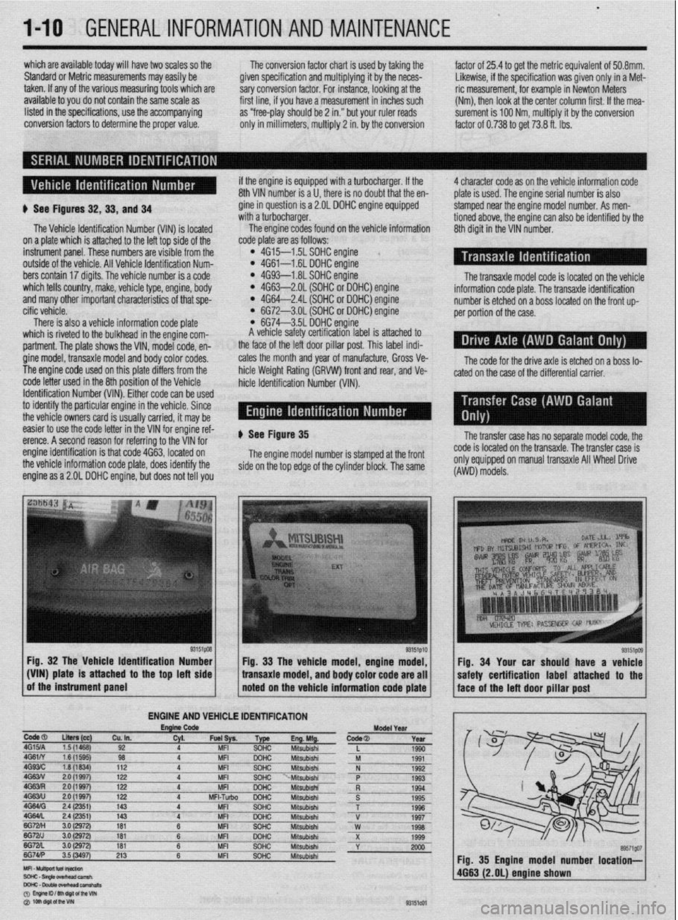
b See Figures 32,33, and 34
The Vehicle Identification Number (VIN) is located
on a plate which is attached to the left top side of the
instrument panel. These numbers are visible from the
outside of the vehicle. All Vehicle Identification Num-
bers contain 17 digits. The vehicle number is a code
which tells country, make, vehicle type, engine, body
and many other important characteristics of that spe-
cific vehicle.
There is also a vehicle information code plate
which is riveted to the bulkhead in the engine com-
partment. The plate shows the VIN, model code, en-
gine model, transaxle model and body color codes.
The engine code used on this plate differs from the
code letter used in the 8th position of the Vehicle
Identification Number (VIN). Either code can be used
to identify the particular engine in the vehicle. Since
the vehicle owners card is usually carried, it may be if the engine is equipped with a turbocharger. If the
8th VIN number is a U, there is no doubt that the en-
gine in question is a 2.OL DOHC engine equipped
with a turbocharger.
The engine codes found on the vehicle information
code plate are as follows:
l 4G15--1.5L SOHC engine l 4G61-1.6L DOHC engine l 4G93-1.8L SOHC engine l 4G63-2.OL (SOHC or DOHC) engine l 4G64-2.4L (SOHC or DOHC) engine l 6G72-3.OL (SOHC or DOHC) engine l 6G74-3.5L DOHC engine
A vehicle safety certification label is attached to
the face of the left door pillar post. This label indi-
cates the month and year of manufacture, Gross Ve-
hicle Weight Rating (GRVW) front and rear, and Ve-
hicle Identification Number (VIM). 4 character code as on the vehicle information code
plate is used. The engine serial number is also
stamped near the engine model number. As men-
tioned above, the engine can also be identified by the
8th digit in the VIN number.
The transaxle model code is located on the vehicle
information code plate. The transaxle identification
number is etched on a boss located on the front up-
per portion of the case.
The code for the drive axle is etched on a boss lo-
cated on the case of the differential carrier.
easier to use the code letter in the VIN for engine ref-
erence. A second reason for referring to the VIN for
engine identification is that code 4663, located on
the vehicle information code plate, does identify the
engine as a 2.OL DOHC engine, but does not tell you ) See Figure 35
The engine model number is stamped at the front
side on the top edge of the cylinder block. The same
Fig. 32 The Vehicle Identification Number
g3’51p’o of the instrument panel _I:^1 / Fig. 33 The vehicle model, engine model,
(VIN) plate is attached to the top left side
bansaxle model, and body color code are all
noted on the vehicle information code plate
ENGINE AND VEHiCLE IDENTlFlCATlON
EnglnCode
ModelYerr
todeal
LIten (cc)
Cu. In. W. Fuel+ Type m.hWg. Code@ Year ,G15JA 1.5 (1468) 92 4 MFI SOHC Mitsubishi
L 1990
IG61N 1.6(15QQ) 98 4 MFI DOHC
Mitsubishi M 1991
1G93lC 1.8 (1834) 112 4 MFI SOHC Mitsubishi N 1992
IG63N 2.0 (1997) 122 4 MFI SOHC “-Mitsubishi P
1993
!G63Fi 2.0 (1997) 122 4 MFI DOHC Mitsubishi
R 1994
,G63iU 2.0 (1997) 122 4 MFI-Tuibo DOHC Mitsubishi
S 1995
.GMffi 2.4 (2351) 143 4 MFI SOHC
Mitsubishi T 1996
iG64L 2.4 (2351) 143 4 MFI DOHC Mitsubishi V
lEzH 3.0 1997
(2972) 161 6 MFI SOHC Mitsubishi W 1998
;G7ZJ 3.0 (2Q72) 161 6 MFI GQHC Mitsubishi
~.. X 1999
iG7zL 3.0 (2972) 181
~ 6 MFI SOHC ___-___ Miisubishi
Y 2000
iG74lP 3.5 (3497) 213 6 MFI SOHC Miisubishi
The transfer case has no separate model code, the
code is located on the transaxle. The transfer case is
onlv eoUiODed on manual transaxle All Wheel Drive
(AWD)‘mbdels.
Fig. 34 Your car should have a vehicle
Fig. 35 Engine model number location-
4663 (2.OL) engine shown
Page 35 of 408
.
l-36 GENERALINFORMATIONAND MAINTENANCE
Install the drain plug and tighten to 22 ft. Ibs.
(304Nm)
5. Refill the transaxle to the proper level, as
shown in the Capacities chart, with the appropriate
fluid. The oil level should be at the bottom of the oil
filler hole. I
6. When the oil reaches the orooer level, install
the filler plug and tighten to 22 ft. Ibs. (30 Nm).
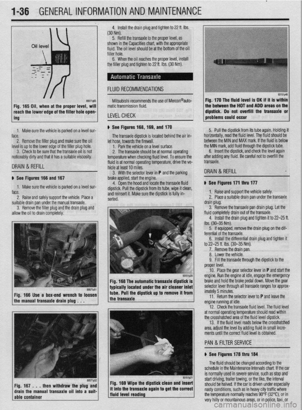
FLUID RECOMMENDATIONS
8957i565 Fig, 165 Oil, when at the proper level, will
reach the lower edge of tC=+ frfr*r u*rn -non-
ing Mitsubishi recommends the use of Mercon@auto-
matic transmission fluid.
LEVELCHECK
Fig. 170 The fluid level is OK if it is within
the between the HOT and ADD areas on the
&&i& Do not overfill the transaxle or
-.*".."... -- .*"- problems could o ccur
1. Makesure the vehicle is oarked on a level sur-
face.
2. Remove the filler plug and make sure the oil
level is up to the lower edge of the filler plug hole.
3. Check to be sure that the transaxle oil is not
noticeably dirty and that it has a suitable viscosity. u See Figures 168,169, and 170
fluid is at normal operating temperature, drive the ve- The transaxle dipstick is located behind the air in-
hicle at least 10 miles. let hose, towards the firewall.
1. Park the vehicle on a level surface.
2. The transaxle should be at normal operating
temperature when checking fluid level. To ensure the 5. Pull the dipstick from its tube again. Holding it
horizontally, road the fluid level. The fkrid should be
between the MIN and MAX mark. If the fluid is below
the MIN mark, add fluid through the dipstick tube.
DRAIN & REFILL
6. Insert the dipstick, and check the level again
after adding any fluid. Be careful not to overfill the
transaxle.
3. With the selector lever in P and the parking
DRAIN & REFILL u See Figures 166 and 167
1. Make sure the vehicle is parked on a level sur-
face.
2. Raise and safely support the vehicle. Place a brake applied, start the engine.
4. Open the hood and locate the transaxle fluid
dipstick. Pull the dipstick from its tube, wipe it clean,
and reinsert it. Make sure the dipstick is fully in-
serted.
suitable drain pan under the manual transaxle.
3. Remove the filler plug and the drain plug and
allow the oil to drain completely.
Fig. 166 The automatic transaxle dipstick is
typically located under the air cleaner inlet
Fig. 166 Use a box-end wrench to loosen
the manual transaxle drain plug . . . tube. Pull the dipstick up to remove it from
the transaxle
Fig. 169 Wipe the dipstick clean and Insert
/fluid level reading ., it mto the transaxle agam to get the correct
j The fluid should be changed according to the
schedule in the Maintenance Intervals chart. If the car
is normally used in severe service, such as stop and
start driving, trailer towing, or the like, the interval
should be halved. If the car is driven under especially
nasty conditions, such as in heavy city traffic where
the temperature normally reaches 90°F (32%), or in
very hilly or mountainous areas, or in police, taxi, or b See Figures 171 thru 177
1. Raise and support the vehicle safely.
2. Place a suitable drain pan under the transaxle
drain plug.
3. Remove the transaxle pan drain plug. Let the
fluid completely drain out of the transaxle.
4. Install the drain plug and tighten it to 22-25 ft.
lbs. (30-35 Nm).
5. If equipped, remove the drain plug on the dif-
ferential of the transaxle.
6. Install the differential drain plug and tighten ft
to 22-25 ft. Ibs. (30-35 Nm).
7. Remove the drain pan.
8. Lower the vehicle.
9. Fill the transaxle through the dipstick to the
proper level.
10. Place the gear selector lever in P and start the
engine. Run the engine at idle, engage the emergency
brake and hold the brake pedal down. Move the gear
selector lever through all transaxle ranges for approx-
imately 5 minutes.
11. Return the selector lever to P and leave the
engine running at idle.
12. Check the transaxle fluid level. The fluid level
at normal operating temperature should read within
the crosshatched area of the fluid level dipstick.
13. If the fluid level reads below the crosshatched
area, adjust the level by adding fluid in small incre-
ments until the correct fluid level is obtained.
PAN &FILTER SERVICE
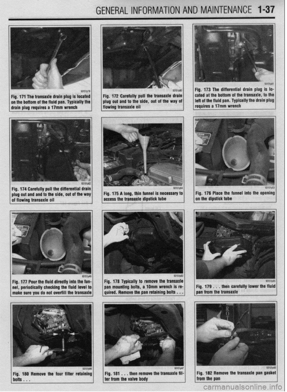
b See Figures 178 thru 184
Page 36 of 408
_. .I ..-.
-._.
GENERALINFORMATIONAND MAINTENANCE l-37
Fig. 172 Carefully pull the transaxie drain
plug out and to the side, out of the way oi
flowing transaxie oil Fig. 173 The differential drain plug is lo-
cated at the bottom of the transaxie, to the
left of the fluid pan. Typically the drain plug
reauires a 17mm wrench
periodically checking the fluid level to
make sure you do not overfill the transaxle pan mounting
bolts, a 1Omm wrench is re-
Fig. 179 . . , then carefully lower the fluid
quired. Remove the pan retaining bolts . . . pan from the transaxle
Fig, 181 . , . then remove the transaxie film
ter from the valve body Fig. 182 Remove the transaxie pan
gasket from the pan
Page 167 of 408
.
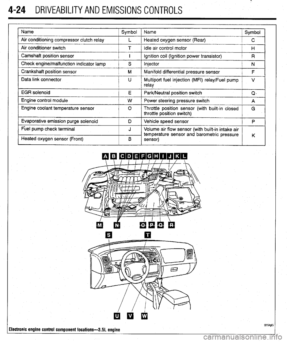
4-24 DRIVEABILITYAND EMISSIONS CONTROLS
Name
Air conditioning compressor clutch relay
Air conditioner switch
Camshaft position sensor
Check engine/malfunction indicator lamp
Crankshaft position sensor
Data link connector
EGR solenoid
Engine control module
Engine coolant temperature sensor
Evaporative emission purge solenoid
Fuel pump check terminal
Heated oxygen sensor (Front) Symbol 1 Name
Symbol
L 1 Heated oxygen sensor (Rear)
C
T / Idle arr control motor
H
I ignition coil (Ignition power transistor)
R
S Injector
N
M Manifold differential pressure sensor
F
U Multiport fuel injection (MFI) relay/Fuel pump V
relay
E Park/Neutral position switch
Q,
W Power steering pressure switch
A
0 Throttle position sensor (with built-in closed
G
throttle position switch)
D Vehicle speed sensor
P
J Volume air flow sensor (with built-in intake air
temperature sensor and barometric pressure
B K
sensor)
ilectronic engine control component locations-3.51 engine
Page 168 of 408
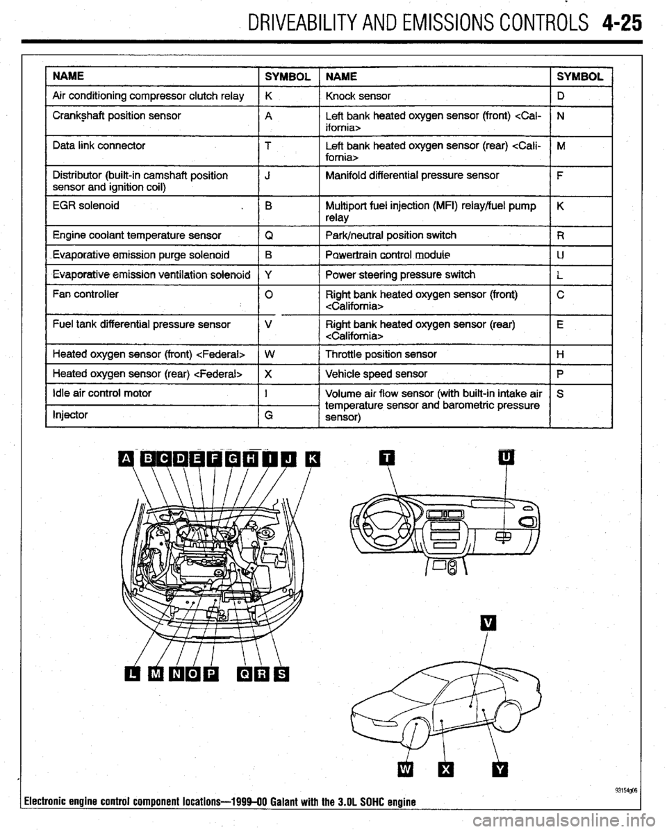
DRIVEABILITYAND EMISSIONS CONTROLS 4-25
NAME
SYMBOL NAME SYMBOL
Air conditioning compressor clutch relay K
Knock sensor D
I Crankshaft position sensor
A Left bank heated oxygen sensor (front)
I I
Data link connector T Left bank heated oxygen sensor (rear)
I Distributor (built-in camshaft position
I J Manifold differential pressure sensor
I F
sensor and ignition coil)
I
EGR solenoid . B Multiport fuel injection (MFI) relay/fuel pump K
relay
1 Engine coolant temperature sensor
IQ 1 Park/neutral position switch IR
Euaporatiue.emission purge solenoid B
Powertraincontrol module LJ
l Evaporatiw5+eiiission ventilation solenoid Y
I Powersteering pressure switch
L
Fan controller 0 Right bank heated oxygen sensor (front) C
Fuel tank differential pressure sensor V Right bank heated oxygen sensor (rear) E
Heated oxygen sensor (front)
I
1 Heated oxygen sensor (rear)
Ip I
Idle air control motor
Injector I
G Volume air flow sensor (with built-in intake air S
temperature sensor and barometric pressure
sensor)
I I
93154@3 lectronic engine control component locations-199940 Galant with the 3.OL SOHC engine
Page 175 of 408
4-32 DRIVEABILITYAND EMISSIONS CONTROLS
PO785 Shift/Timing Solenoid Malfunction
PO786 Shift/Timing Solenoid Range/Performance
PO787 Shift/Timing Solenoid Low
PO788 Shift/Timing Solenord High
PO789 Shift/Timing Solenoid Intermittent
PO790 Normal/Performance Switch Circuit Mal-
function
PO801 Reverse Inhibit Control Circuit Malfunc-
tion
PO803 l-4 Upshift (Skip Shift) Solenoid Control
Circuit Malfunction
PO804 l-4 Upshift (Skip Shift) Lamp Control
Circuit Malfunction
PllOO Induction Control Motor Position Sensor
Fault
PI101 Traction Control Vacuum Solenoid Circuit
Fault
Pl102 Traction Control Ventilation Solenoid Cir-
cuit Fault P1294 Target Idle Speed Not Reached
P1295 No 5-Volt Supply To TP Sensor
P1296 No 5-Volt Supply To MAP Sensor
P1297 No Change In MAP From Start To Run
PI300 Ignition Timing Adjustment Circuit
Pl390 Timing Belt Skipped One Tooth Or More
Pl391 Intermittent Loss Of CMP Or CKP Sensor
Signals P1495 EVAP Ventilation Solenoid Circurt Fault
P1496 5-Volt Supply Output Too Low
Pl500 Generator FR Terminal Circuit Fault
Pl600 PCM-TCM Serial Communication Link
Circuit Fault
Pl400 Manifold Differential Pressure Sensor
Fault P1696 PCM Failure- EEPROM Write Denied
Pl715 No CCD Messages From TCM
Pl750 TCM Pulse Generator Circuit Fault
Pl791 Pressure Control, Shift Control, TCC So-
lenoid Fault
P1443 EVAP Purge Control Solenoid “2” Circuit
Fault P1899 PCM ECT Level Signal to TCM Circuit
Fault
P1486 EVAP Leak Monitor Pinched Hose De-
tected
P1989 High Speed Condenser Fan Control Relay
Fault
P1487 High Speed Radiator Fan Control Relay
Circuit Fault
Pl490 Low Speed Fan Control Relay Fault
P1492 Battery Temperature Sensor High Voltage
P1494 EVAP Ventilation Switch Or Mechanical
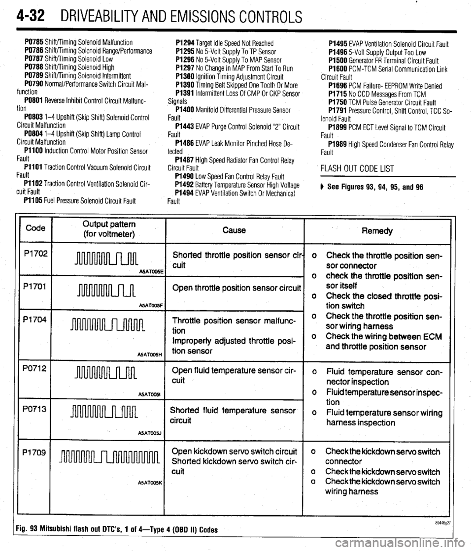
FLASH OUT CODE LIST
# See Figures
93, 94, 95, and 96
Fault PI105 Fuel Pressure Solenoid Circuit Fault
Code
Output pattern
(for voltmeter) Cause
P1702
Shorted throttle position sensor cil
cuit
MATOOSE
Pl701
Open throttle position sensor circuii
A!iATW5F
p1704 -
Throttle position sensor malfunc-
tion
Improperly adjusted throttle posi-
ASATmH tion sensor
PO71 2
Open fluid temperature sensor cir-
u 1 cuit
ASAT
PO71 3
Shorted fluid temperature sensor
circuit
ASATOOU
Pl709
I I Open kickdown servo switch circuit
Shorted kickdown servo switch cir-
cuit
A5ATOOSK
Remedy
o Check the throttle position sen-
sor connector
o check the throttle position sen-
sor itself
o Check the closed throttle posi-
tion switch
o Check the throttle position sen-
sor wiring harness
o Check the wiring between ECM
and throttle position sensor
o Fluid temperature sensor con-
nector inspection
o Fluid temperature sensor inspec-
tion
o Fluid temperature sensor wiring
harness inspection
o Check the kickdown servo switch
connector
o Check the kickdown servo switch
o Checkthe kickdown servo switch
wiring harness
Fig. 93 Mitsubishi flash out DTC's, 1 of 4-Type 4 (DBD II) Codes
Page 200 of 408
FUELSYSTiM 5-13
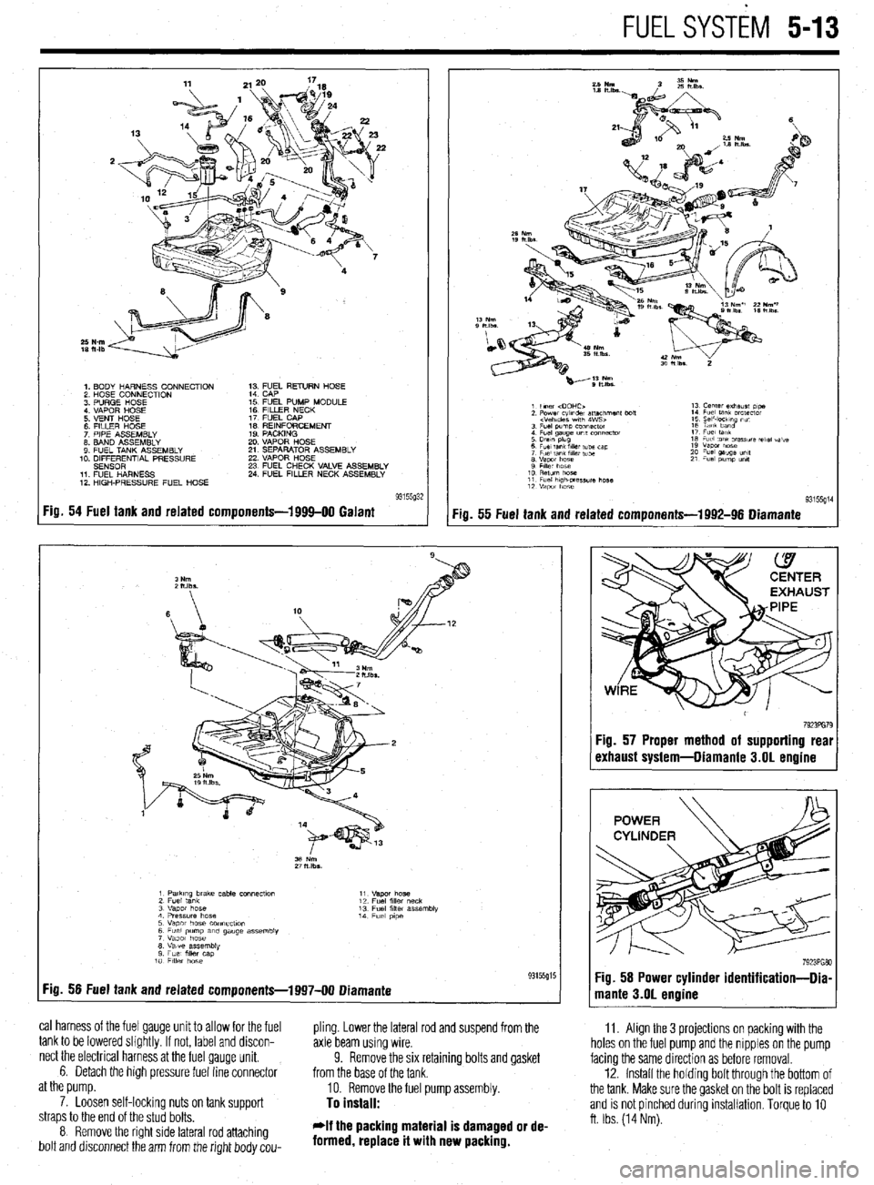
1. BODY HARNESS CONNECTION
2 HOSE CONNECTION
3 PURGE HOSE
4 VAPOR HOSE
5 VENT HOSE
6 FllLER HOSE
7 PIPE ASSEMBLY
8. BAND ASSEMBLY
9 FUEL TANK ASSEMBLY
10. DIFFERENTIAL PRESSURE
SENSOR
11 FUEL HARNESS
12 HIGH-PRESSURE FUEL HOSE 1; ;;JL RETURN HOSE
15 FUEL PUMP MODULE
16 FILLER NECK
17 FUEL CAP
IS REINFORCEMENT
19 PACKING
20 VAPOR HOSE
21 SEPARATOR ASSEMBLY
22 VAPOR HOSE
23 FUEL CHECK VALVE ASSEMBLY
24 FUEL FILLER NECK ASSEMBLY
Fig. 54 Fuel tank and related components-1999-00 Galant
:ia. 55 Fuel tank and related components-1992-96 Diamante
11. Align the 3 projections on packing with the
holes on the fuel pump and the nipples on the pump
facing the same direction as before removal.
12. Install the holdrng bolt through the bottom of
the tank. Make sure the gasket on the bolt is replaced
and is not pinched during installation. Torque to 10
ft. Ibs. (14 Nm).
1 PatkIng brake cable COnneCtlo” 11
2 Fuel tank “.qm hose
12 Fuel fllk, neck
3 “apot hose 13 Fuel filler assembly
4 Pressure hose 14
5 Vapor hose COnneCflOn Fuel p,pe
6 Fuel pump am gauge assembly
7 Vapor hose
8 Valve assembly
9 Fuel mer cap
10 FllkY hose
:ig. 56 Fuel tank and related components-1997-00 Diamante 93155g15
cal harness of the fuel gauge unit to allow for the fuel
pling. Lower the lateral rod and suspend from the
tank to be lowered slightly. If not, label and discon-
axle beam using wire.
nect the electrical harness at the fuel gauge unit.
6. Detach the high pressure fuel line connector 9. Remove the six retaining bolts and gasket
from the base of the tank.
at the pump.
10. Remove the fuel pump assembly.
7. Loosen self-lockinq nuts on tank suooort
To install: straps to the end of the stud bolts.
8 Remove the right side lateral rod attaching
bolt and drsconnect the arm from the right body cou- *If the packing material is damaged or de-
formed, replace it with new packing.
7923PG79 :ig. 57 Proper method of supporting real
rxhaust system-Diamante 3.01 engine