1900 MITSUBISHI DIAMANTE oil viscosity
[x] Cancel search: oil viscosityPage 32 of 408
GENERALINFORMATIONAND MAINTENANC-E 1133
Used fluids such as engine oil, transaxle fluid, an-
tifreeze and brake fluid are hazardous wastes and
must be disposed of properly. Before draining any
fluids, consult with your local authorities; in many ar-
eas, waste oil, antifreeze, etc. is being accepted as a
part of recycling programs. A number of service sta-
tions and auto parts stores are also accepting waste
fluids for recycling.
Be sure of the recycling center’s policies before
draining any fluids, as many will not accept different
fluids that have been mixed together.
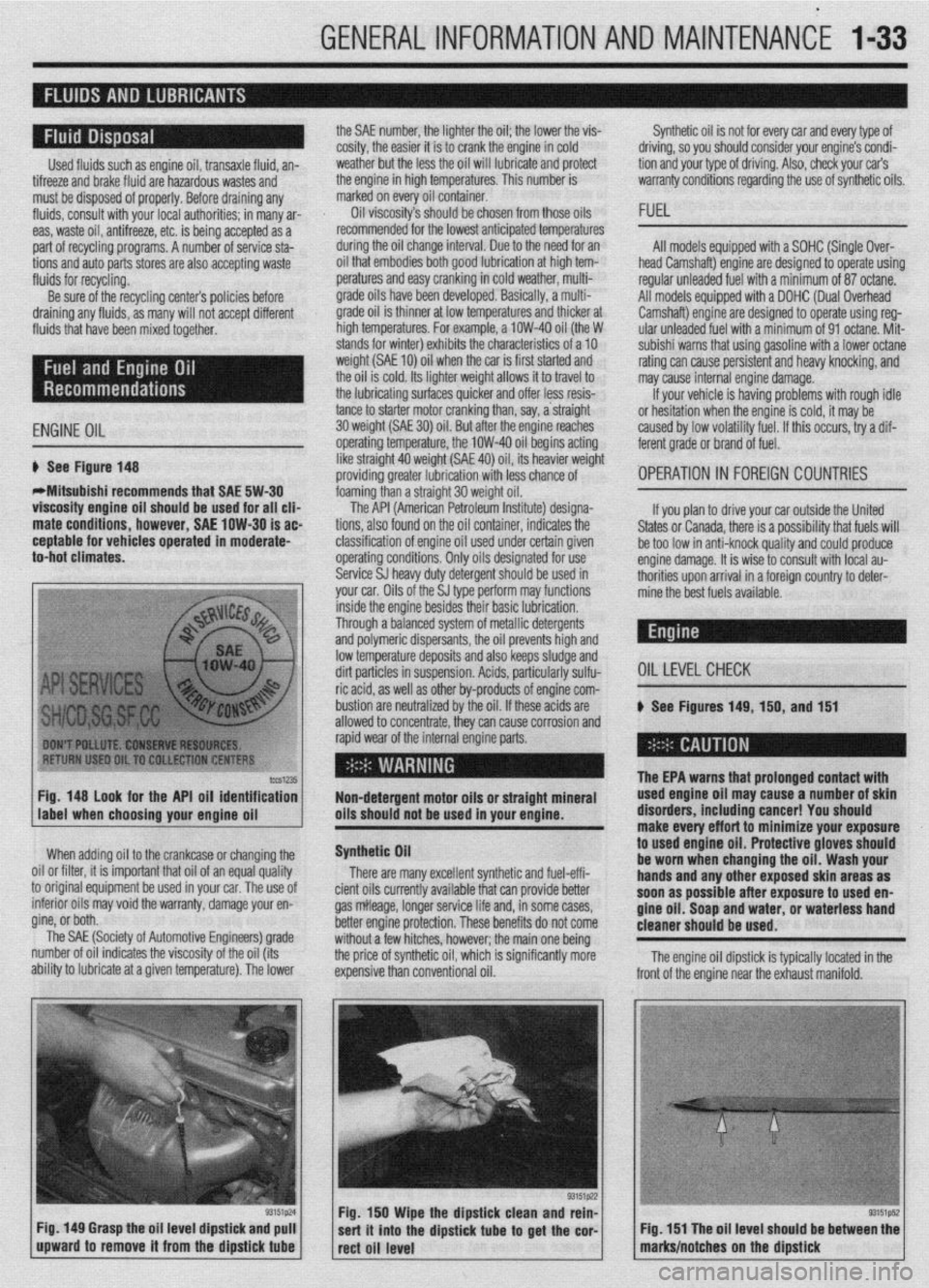
ENGINE OIL
6 See Figure 148
WMitsubishi recommends that SAE 5W-30
viscosity engine oil should be used for all clia
mate conditions, however, SAE low-30 is ac
ceptable for vehicles operated in moderate-
to-hot climates. the SAE number, the lighter the oil; the lower the vis-
cosity, the easier it is to crank the engine in cold
weather but the less the oil will lubricate and protect
the engine in high temperatures. This number is
marked on every oil container.
Oil viscosity’s should be chosen from those oils
recommended for the lowest anticipated temperatures
during the oil change interval. Due to the need for an
oil that embodies both good lubrication at high tem-
peratures and easy cranking in cold weather, multi-
grade oils have been developed. Basically, a multi-
grade oil is thinner at low temperatures and thicker at
high temperatures. For example, a low-40 oil (the W
stands for winter) exhibits the characteristics of a 10
weight (SAE 10) oil when the car is first started and
the oil is cold. Its lighter weight allows it to travel to
the lubricating surfaces quicker and offer less resis-
tance to starter motor cranking than, say, a straight
30 weight (SAE 30) oil. But atier the ensine reaches
operating temperature, the low-40 oil begins acting
like straight 40 weight (SAE 40) oil, its heavier weight
providing greater lubrication with less chance of
foaming than a straight 30 weight oil. Synthetic oil is not for every car and every type of
driving, so you should consider your engine’s condi-
tion and your type of driving. Also, check your car’s
warranty conditions regarding the use of synthetic oils.
FUEL
All models equipped with a SOHC (Single Over-
head Camshaft) engine are designed to operate using
regular unleaded fuel with a minimum of 87 octane.
All models equipped with a DOHC (Dual Overhead
Camshaft) engine are designed to operate using reg-
ular unleaded fuel with a minimum of 91 octane. Mit-
subishi warns that using gasoline with a lower octane
rating can cause persistent and heavy knocking, and
may cause internal engine damage.
If your vehicle is having problems with rough idle
or hesitation when the enoine is cold, it mav be
caused by low volatility fuel. If this occurs, iry a dif-
ferent grade or brand of fuel.
'OPERATION 1~ FOREIGN COUNTRIES
lccS1235 Fig. 148 look for the API oil identification
Non-detergent motor oils or straight mineral
label when choosing your enaine oil oils should not be used in your engine.
When adding oil to the crankcase or changing the
0 Nil or filter, it is important that oil of an equal quality
I original equipment be used in your car. The use of
. tc mtenor 011s may void the warranty, damage your en-
gine, or both. __
The SAE (Society of Automotive Engineers) grade
number of oil indicates the viscosity of the oil (its
ability to lubricate at a given temperature). The lower
Fig. 149 Grasp the oil level dipstick and pull
upward to remove it from the dipstick
tube
The API (American Petroleum Institute) designa-
tions, also found on the oil container, indicates the
classification of engine oil used under certain given
operating conditions. Only oils designated for use
Service SJ heavy duty detergent should be used in
your car. Oils of the SJ type perform may functions If you plan to drive your car outside the United
States or Canada, there is a possibility that fuels will
be too low in anti-knock quality and could produce
engine damage. It is wise to consult with local au-
thorities upon arrival in a foreign country to deter-
mine the best fuels available.
inside the engine besides their basic lubrication.
Through a balanced system of metallic detergents
and polymeric dispersants, the oil prevents high and
low temperature deposits and also keeps sludge and
dirt particles in suspension. Acids, particularly sulfu-
OILLEVELCHECK ric acid, as well as other by-products of engine com-
bustion are neutralized by the oil. If these acids are
# See Figures 149, 150, and 151
allowed to concentrate, thev can cause corrosion and
rapid wear of the internal engine parts.
Synthetic Oil
There are many excellent synthetic and fuel-effi-
cient oils currently available that can provide better
gas mileage, longer service life and, in some cases,
better engine protection. These benefits do not come
without a few hitches, however; the main one being
the price of synthetic oil, which is significantly more
expensive than conventional oil.
.
The EPA warns that urolonoed contact with used engine oil ma; cause-a number of skin
disorders, including cancer! You should
make every effort to minimize your exposure
to
used engine oil. Protective gloves should
be worn when changing the oil. Wash your
hands and any other exposed skin areas as
soon as possible after exposure to used en-
gine oil. Soap and water, or waterless hand
cleaner should be used.
Fig. 150 Wipe the dipstick clean and rein-
sert it into the dipstick
tube to get the cor-
rect oil level The engine oil dipstick is typically located in the
Fig. 151 The oil level should be between the
marks/notches on the dipstick
Page 33 of 408
.
l-34 GENERALINFORMATIONAND MAINTENANCE
Engine oil level should be checked every time you
put fuel in the vehicle or are under the hood perform- miles of highway driving. Fluid which is warmed to
normal operating temperature will flow faster, drain
ing other maintenance.
1. Park the vehicle on a level surface.
2. The enaine mav be either hot or cold when
, if it is hot, wait a few min- checking oil level. The EPA warns that prolonged contact with
used engine oil may cause a num’ * * *
dianrAnrr inrldinn ranrnrl V#lll more completely and remove more contaminants
frnm tho clnnine
utes after the engine has been turned OFF to allow the
oil to drain back into the crankcase. If the engine is
cold, do not start it before checking the oil level. point on the oil pan. If not, you may have to raise the
vehicle slightly higher on one jackstand (side) than
3. Open the hood and locate the engine oil dip-
stick. Pull the dipstick from its tube, wipe it clean,
and reinsert it. Make sure the diDstick is fullv in-
serted.
4. Pull the dipstick from its tube again. Holding it to used engin
be worn whet
handsandan
so*m ..#a . . . . .
IDer 01 SKlll u,yu,u=,+, ,,,u,uu,,,u uu,,u=, i , vu should
uff art to minimize your exposure
le oil. Protective gloves should
1 changing the oil. Wash your
y other exposed skin areas as
111 aJ vv4ble after exposure to used en-
m nil St-mn mwl w&or nr umtarlncr hand gin Y “II. ““up “ll” .,U.“I, “rn W.Y.“. .““I .I....” cleaner should be used.
horizontally, read the oil level. The oilshould be be-
tween the MIN and MAX marks or the notches on the
dipstick. If the oil is below the MIN mark or lower
notch, add oil of the proper viscosity through the
capped opening of the valve cover. *The engine oil and oil filter should be
changed at the recommended intervals on
the Maintenance Chart. Though some manu-
facturers have at times recommended chang-
ing the filter only at every other oil change, ’
Chilton recommends that you always change
ll”,,, Cl>” ““y”‘“. 1. Raise and support the vehicle safely on jack-
stands. Make sure the oil drain olua is at the lowest
the other.
2. Before you crawl under the vehicle, take a look
at where you will be working and gather all the nec-
essary tools, such as a few wrenches or a ratchet and
strip of sockets, the drain pan, some clean rags and,
if the oil filter is more accessible from underneath the
vehicle, you will also want to grab a bottle of oil, the
new filter and a filter wrench at this time.
5. Reolace the diostick. and check the level aaain
. The benefit of fresh oil
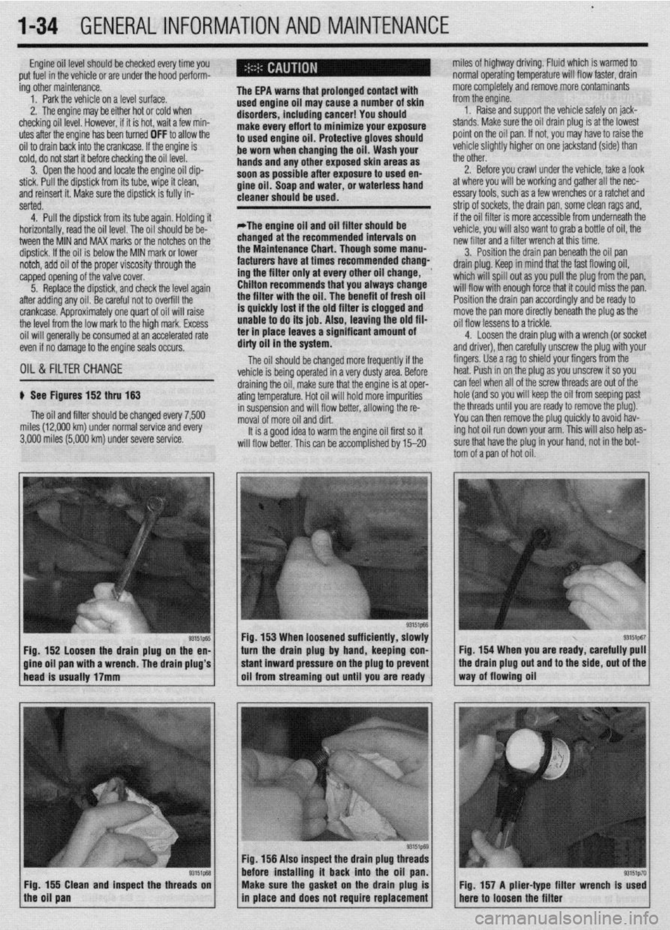
p See Figures 152 thru 153
The oil and filter should be changed every 7,500
miles (12,000 km) under normal service and every
3,000 miles (5,000 km) under severe service.
93151p-55 Fig. 152 loosen the drain plug on the en-
a wrench. The drain plug’s 3. Position the drain pan beneath the oil pan
drain plug. Keep in mind that the fast flowing oil,
which will spill out as you pull the plug from the pan,
will flow with enough force that it could miss the pan.
Position the drain pan accordingly and be ready to
move the pan more directly beneath the plug as the
oil flow lessens to a trickle.
4. Loosen the drain ~lua with a wrench (or socket
and driver), then carefuliy unscrew the plug with your
fingers. Use a rag to shield your fingers from the
heat. Push in on the plug as you unscrew it so you
draining the oil, make sure that the engine is at oper- can feel when all of the screw threads are out of the
ating temperature. Hot oil will hold more impurities hole (and so you will keep the oil from seeping past
in suspension and will flow better, allowing the re- the threads until you are ready to remove the plug).
moval of more oil and dirt. You can then remove the plug quickly to avoid hav-
It is a good idea to warm the engine oil first so it ing hot oil run down your arm. This will also help as-
will flow better. This can be accomolished bv 15-20 sure that have the plug in your hand, not in the bot-
tom of a pan of hot oil.
Fig. 153 When loosened sufficiently, slowly
turn the drain plug by hand, keeping con- Fig. 154 When you are ready, carefully pull
Fig. 156 Also inspect the drain plug th
before installing it back into the oil
Fig. 155 Clean and inspect the threads on
the oil pan Make sure the gasket on the drain plug is
in place and does not require replacement Fig. 157 A plier-type filter wrench Is used
here to loosen the filter
Page 35 of 408
.
l-36 GENERALINFORMATIONAND MAINTENANCE
Install the drain plug and tighten to 22 ft. Ibs.
(304Nm)
5. Refill the transaxle to the proper level, as
shown in the Capacities chart, with the appropriate
fluid. The oil level should be at the bottom of the oil
filler hole. I
6. When the oil reaches the orooer level, install
the filler plug and tighten to 22 ft. Ibs. (30 Nm).
FLUID RECOMMENDATIONS
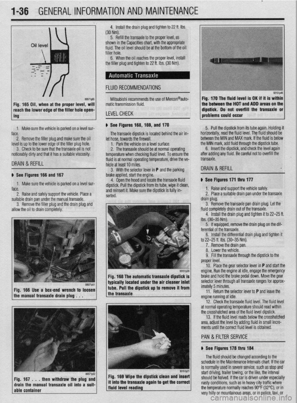
8957i565 Fig, 165 Oil, when at the proper level, will
reach the lower edge of tC=+ frfr*r u*rn -non-
ing Mitsubishi recommends the use of Mercon@auto-
matic transmission fluid.
LEVELCHECK
Fig. 170 The fluid level is OK if it is within
the between the HOT and ADD areas on the
&&i& Do not overfill the transaxle or
-.*".."... -- .*"- problems could o ccur
1. Makesure the vehicle is oarked on a level sur-
face.
2. Remove the filler plug and make sure the oil
level is up to the lower edge of the filler plug hole.
3. Check to be sure that the transaxle oil is not
noticeably dirty and that it has a suitable viscosity. u See Figures 168,169, and 170
fluid is at normal operating temperature, drive the ve- The transaxle dipstick is located behind the air in-
hicle at least 10 miles. let hose, towards the firewall.
1. Park the vehicle on a level surface.
2. The transaxle should be at normal operating
temperature when checking fluid level. To ensure the 5. Pull the dipstick from its tube again. Holding it
horizontally, road the fluid level. The fkrid should be
between the MIN and MAX mark. If the fluid is below
the MIN mark, add fluid through the dipstick tube.
DRAIN & REFILL
6. Insert the dipstick, and check the level again
after adding any fluid. Be careful not to overfill the
transaxle.
3. With the selector lever in P and the parking
DRAIN & REFILL u See Figures 166 and 167
1. Make sure the vehicle is parked on a level sur-
face.
2. Raise and safely support the vehicle. Place a brake applied, start the engine.
4. Open the hood and locate the transaxle fluid
dipstick. Pull the dipstick from its tube, wipe it clean,
and reinsert it. Make sure the dipstick is fully in-
serted.
suitable drain pan under the manual transaxle.
3. Remove the filler plug and the drain plug and
allow the oil to drain completely.
Fig. 166 The automatic transaxle dipstick is
typically located under the air cleaner inlet
Fig. 166 Use a box-end wrench to loosen
the manual transaxle drain plug . . . tube. Pull the dipstick up to remove it from
the transaxle
Fig. 169 Wipe the dipstick clean and Insert
/fluid level reading ., it mto the transaxle agam to get the correct
j The fluid should be changed according to the
schedule in the Maintenance Intervals chart. If the car
is normally used in severe service, such as stop and
start driving, trailer towing, or the like, the interval
should be halved. If the car is driven under especially
nasty conditions, such as in heavy city traffic where
the temperature normally reaches 90°F (32%), or in
very hilly or mountainous areas, or in police, taxi, or b See Figures 171 thru 177
1. Raise and support the vehicle safely.
2. Place a suitable drain pan under the transaxle
drain plug.
3. Remove the transaxle pan drain plug. Let the
fluid completely drain out of the transaxle.
4. Install the drain plug and tighten it to 22-25 ft.
lbs. (30-35 Nm).
5. If equipped, remove the drain plug on the dif-
ferential of the transaxle.
6. Install the differential drain plug and tighten ft
to 22-25 ft. Ibs. (30-35 Nm).
7. Remove the drain pan.
8. Lower the vehicle.
9. Fill the transaxle through the dipstick to the
proper level.
10. Place the gear selector lever in P and start the
engine. Run the engine at idle, engage the emergency
brake and hold the brake pedal down. Move the gear
selector lever through all transaxle ranges for approx-
imately 5 minutes.
11. Return the selector lever to P and leave the
engine running at idle.
12. Check the transaxle fluid level. The fluid level
at normal operating temperature should read within
the crosshatched area of the fluid level dipstick.
13. If the fluid level reads below the crosshatched
area, adjust the level by adding fluid in small incre-
ments until the correct fluid level is obtained.
PAN &FILTER SERVICE
b See Figures 178 thru 184
Page 37 of 408
t
1-38 GENERALINFORMATIONAND MAINTENANCE
11 I Add the recommended automatic transaxle
fluid to the transaxle through the dipstick tube. You
will need a long necked funnel, or a funnel and tube
to do this. A quick check of the capacities chart later
in this Section will reveal the capacity of the transaxle
in your vehicle. On a first fill after removing the pan
and filter, this number should be cut into a ‘hand
checked on the dipstick before refilling.
12. With the transaxle in P, put on the parking
brake, block the front wheels, start the engine and let
it idle. DO NOT RACE THE ENGINE. DO NOT MOVE
THE LEVER THROUGH ITS RANGES.
13. With the lever in Park, check the fluid level. If
it’s OK, take the car out for a short drive, park on a
level surface, and check the level again, as outlined
earlier in this section. Add more fluid if necessary. Be
careful not to overfill, which will cause foaming and
w fluid loss. n of the transfer case filler
3. Remove the filler and the drain plug and allow
the oil to drain into the drain pan.
4. After the fluid has drained completely, install
the drain plug and tighten to 24 ft. Ibs. (32 Nm).
5. Refill the transfer case to the proper level with
Fig. 184 . . .
the transaxle case before in-
stalling the gasket
and pan onto the case FLUID RECOMMENDATIONS Hypoid gear oil SAE 75W-85W/75W-9OW conform-
ing to API specifications GL-4 or higher. The oil level
-‘-,*I’ -nnnh +‘* “%om edge of the oil filler hole.
nxfer raw filler nlm and tinhtm When adding fluid or refilling the transfer case,
use Hypoid gear oil SAE 75W-85W or 75W-9OW
conforming to API specifications 61-4 or higher.
LEVELCHECK 6. Install the tra .._._. ____ .._. T.-J _.._ .lJ . .._..
to 24 ft. lbs. (32 Nm).
7. Carefully lower the vehicle.
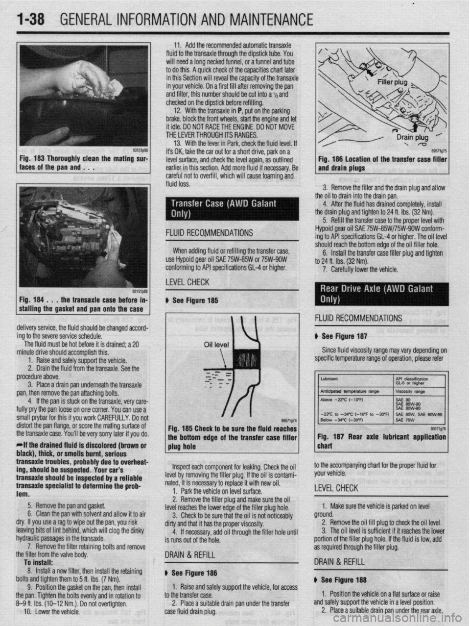
u See Figure 185
, 1 FLUID RECOMMENDATIONS
delivery service, the fluid should be changed accord-
ing to the severe service schedule.
The fluid must be hot before it is drained; a 20 u See Figure 187
Since fluid viscosity range may
vary depending on
specific temperature range of operation, please refer
~~
tne transaxle case.
You’ll be very sorry later if you do. bottom edge of the transfer case filler 1 1 Fig. 187 Rear axle lubricant application I
*If the drained fluld is discolored (brown or
1 plug hole chart black), thick, or pmmll~ hmmt nnrinmm I transaxle trouble .llln3llU ““III., url,““P s, probably due to overheat-
,r..rr,rA “#.a.- rrdr
trig, should be susp~~lr;u. lvUl vLlr J
transaxle should be inspected by a reliable
transaxle specialist to determine the prob-
lem.
5. Remove the pan and gasket.
6. Clean the pan with solvent and allow it to air
dry. If you use a rag to wipe out the pan, you risk
leaving bits of lint behind, which will clog the dinky
hydraulic passages in the bansaxle.
7. Remove the filter retaining bolts and remove
the filter from the valve bodv. lnsoect each component for leaking. Check the oil
he filler plug. If the oil is contami-
ry to replace it with new oil.
if% nn IPVPI z11rf2r~
level by removing t
nated, it is necessa
1. Park the vehi,., -.. ,-.“, __. ,“-_.
2. Remove the filler plug and make sure the oil
level reaches the lower edge of the filler plug hole.
3. Check to be sure that the oil is not noticeably
dirty and that it has the proper viscosity.
4. If necessary, add oil through the filler hole until
is runs out of the hole. to the accompanying chart for the proper fluid for
your vehicle.
LEVEL CHECK
1. Make sure the vehicle is parked on level
ground.
2. Remove the oil fill plug to check the oil level.
3. The oil level is sufficient if it reaches the lower
portion of the filler plug hole. If the fluid is low, add
as required through the filler plug.
To install: .
8. Install a new filter, then install the retaining
bolts and tighten them to 5 ft. Ibs. (7 Nm).
9. Position the gasket on the pan, then install
the pan. Tighten the bolts evenly and in rotation to
8-9ft. Ibs. (10-12 Nm.). Do not overtighten.
IO. Lower the vehicle. DRAIN & REFILL
I8 DRAIN & REFILL
u See Figure 188 ) See Figure- 14
1. Raise and safely support the vehicle, for access
to the transfer case.
2. Place a suitable drain pan under the transfer
case fluid drain plug. 1. Position the vehicle on a flat surface or raise
and safely support the vehicle in a level position.
2. Place a suitable drain pan under the rear axle.
Page 118 of 408
ENGINEANDENGINEOVERHAUL 3-57
Anything that generates heat and/or friction WIII
eventually burn or wear out (for example, a light bulb
generates heat, therefore its life span is limited). With
this in mind, a running engine generates tremendous
amounts of both; friction is encountered by the mov-
ing and rotating parts inside the engine and heat is
created by friction and combustion of the fuel How-
ever, the engine has systems designed to help reduce
the effects of heat and friction and provide added
longevrty. The oiling system reduces the amount of
friction encountered by the moving parts inside the
engine, while the cooling system reduces heat cre-
ated by friction and combustion If either system is
not maintained, a break-down will be inevitable.
Therefore, you can see how regular maintenance can
affect the service life of your vehicle, If you do not
drain, flush and refill your cooling system at the
proper intervals, deposits WIII begin to accumulate in
the radiator, thereby reducing the amount of heat it
can extract from the coolant The same applies to
your oil and filter; If it is not changed often enough it
becomes laden with contaminates and is unable to
properly lubricate the engine. This increases friction
and wear.
There are a number of methods for evaluating the
condition of your engine. A compression test can re-
veal the condition of your pistons, piston rings,
cylinder bores, head gasket(s), valves and valve
seats. An oil pressure test can warn you of possible
engine bearing, or oil pump failures. Excessrve oil
consumption, evidence of oil in the engine air intake
area and/or bluish smoke from the tailpipe may indi-
cate worn piston rings, worn valve guides and/or
valve seals. As a general rule, an engine that uses no
more than one quart of oil every 1000 miles is in
good condition. Engines that use one quart of oil or
more in less than 1000 miles should first be checked
for oil leaks. If any oil leaks are present, have them
fixed before determining how much oil is consumed
by the engine, especrally if blue smoke is not visible
at the tailpipe
COMPRESSION TEST
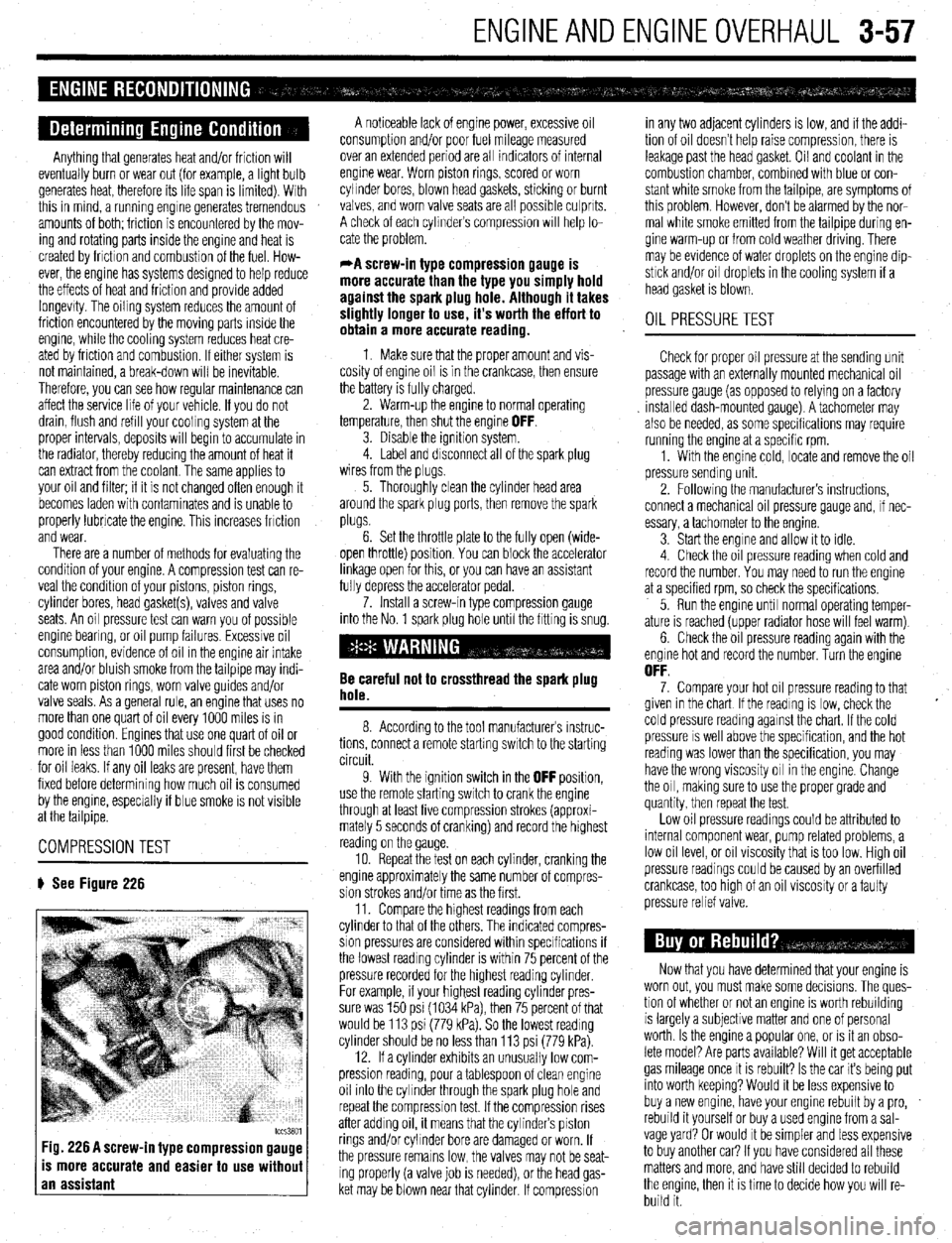
# See Figure 226
tccs3801 Fig. 226 A screw-in type compression gauge
is more accurate and easier to use without
an assistant
A noticeable lack of engine power, excessive oil
consumption and/or poor fuel mileage measured
over an extended period are all indicators of internal
engine wear. Worn piston rings, scored or worn
cylinder bores, blown head gaskets, sticking or burnt
valves, and worn valve seats are all possible culprits.
A check of each cylinders compression WIII help lo-
cate the problem.
*A screw-in type compression gauge is
more accurate than the type you simply hold
against the spark plug hole. Although it takes
slightly longer to use, it’s worth the effort to
obtain a more accurate reading.
1 Make sure that the proper amount and vis-
cosity of engine oil is in the crankcase, then ensure
the battery is fully charged.
2. Warm-up the engine to normal operating
temperature, then shut the engine
OFF. 3. Disable the ignition system.
4. Label and disconnect all of the spark plug
wires from the plugs,
5. Thoroughly clean the cylinder head area
around the spark plug ports, then remove the spark
plugs.
6. Set the throttle plate to the fully open (wide-
open throttle) position You can block the accelerator
linkage open for this, or you can have an assistant
fully depress the accelerator pedal.
7. Install a screw-in type compression gauge
into the No. 1 spark plug hole until the fitting is snug.
Be careful not to crossthread the spark plug
hole.
8. According to the tool manufacturers instruc-
tions, connect a remote starting switch to the starting
circuit.
9. With the ignition switch in the
OFF position,
use the remote starting switch to crank the engine
through at least five compression strokes (approxi-
mately 5 seconds of cranking) and record the highest
reading on the gauge
10. Repeat the test on each cylinder, cranking the
engine approximately the same number of compres-
sion strokes and/or time as the first.
11. Compare the hrghest readings from each
cylinder to that of the others. The indicated compres-
sion pressures are considered within specifications if
the lowest reading cylinder is within 75 percent of the
pressure recorded for the highest reading cylinder
For example, if your highest reading cylinder pres-
sure was 150 psi (1034 kPa), then 75 percent of that
would be 113 psi (779 kPa). So the lowest reading
cylinder should be no less than 113 psi (779 kPa).
12. If a cylinder exhibits an unusually low com-
pression reading, pour a tablespoon of clean engine
oil into the cylinder through the spark plug hole and
repeat the compression test. If the compression rises
after adding oil, it means that the cylinder’s piston
rings and/or cylinder bore are damaged or worn, If
the pressure remains low, the valves may not be seat-
ing properly (a valve job is needed), or the head gas-
ket may be blown near that cylinder. If compression in any two adjacent cylinders is low, and if the addi-
tion of oil doesn’t help raise compression, there is
leakage past the head gasket. Oil and coolant in the
combustion chamber, combined with blue or con-
stant white smoke from the tailpipe, are symptoms of
this problem. However, don’t be alarmed by the nor-
mal white smoke emitted from the tailpipe during en-
gine warm-up or from cold weather driving. There
may be evidence of water droplets on the engine dip-
stick and/or oil droplets in the cooling system if a
head gasket is blown.
OIL PRESSURETEST
Check for proper oil pressure at the sending unit
passage with an externally mounted mechanical oil
pressure gauge (as opposed to relying on a factory
Installed dash-mounted gauge). A tachometer may
also be needed, as some specifications may require
running the engine at a specific rpm.
1. With the engine cold, locate and remove the oil
pressure sending unit.
2. Followrng the manufacturers instructions,
connect a mechanical oil pressure gauge and, if nec-
essary, a tachometer to the engine.
3 Start the engine and allow it to idle.
4 Check the oil pressure reading when cold and
record the number. You may need to run the engine
at a specified rpm, so check the specifications,
5. Run the engine until normal operating temper-
ature is reached (upper radiator hose will feel warm)
6. Check the oil pressure reading again with the
engine hot and record the number. Turn the engine
OFF. 7. Compare your hot oil pressure reading to that
given in the chart If the reading is low, check the
cold pressure reading against the chart. If the cold
pressure IS well above the specification, and the hot
reading was lower than the specification, you may
have the wrong viscosity oil in the engine. Change
the oil, making sure to use the proper grade and
quantity, then repeat the test.
Low oil pressure readings could be attributed to
internal component wear, pump related problems, a
low oil level, or oil viscosity that is too low. High oil
pressure readings could be caused by an overfilled
crankcase, too htgh of an oil viscosity or a faulty
pressure relief valve.
Now that you have determined that your engine is
worn out, you must make some decisions. The ques-
tion of whether or not an engine IS worth rebuilding
is largely a subjective matter and one of personal
worth. Is the engine a popular one, or IS it an obso-
lete model? Are parts available? Will it get acceptable
gas mileage once It is rebuilt? Is the car its being put
into worth keeping? Would it be less expensive to
buy a new engine, have your engine rebuilt by a pro,
rebuild it yourself or buy a used engine from a sal-
vage yard? Or would It be simpler and less expensive
to buy another car? If you have considered all these
matters and more, and have still decided to rebuild
the engine, then it is time to decide how you will re-
build it.
Page 402 of 408
II-20 GLOSSARY
SECONDARY CIRCUIT: The high voltage side of the ignition system, usu-
ally above 20,000 volts. The secondary includes the ignition coil, coil wire,
distributor cap and rotor, spark plug wires and spark plugs.
SENDING UNIT: A mechanical, electrical, hydraulic or electromagnetic de-
vice which transmits information to a gauge.
SENSOR: Any device designed to measure engine operating conditions or
ambient pressures and temperatures. Usually electronic in nature and designed
to send a voltage signal to an on-board computer, some sensors may oper-
ate as a simple on/off switch or they may provide a variable voltage signal
(like a potentiometer) as conditions or measured parameters change.
SHIM: Spacers of precise, predetermined thickness used between parts to es-
tablish a proper working relationship.
SLAVE CYLINDER: In automotive use, a device in the hydraulic clutch sys-
tem which is activated by hydraulic force, disengaging the clutch.
SOLENOID: An electrically operated, magnetic switching device.
SPARK PLUG: A device screwed into the combustion chamber of a spark ig-
nition engine. The basic construction is a conductive core inside of a ceramic
insulator, mounted in an outer conductive base. An electrical charge from the
spark plug wire travels along the conductive core and jumps a preset air gap
to a grounding point or points at the end of the conductive base. The resul-
tant spark ignites the fuel/air mixture in the combustion chamber.
SPLINES: Ridges machined or cast onto the outer diameter of a shaft or in-
ner diameter of a bore to enable parts to mate without rotation.
TACHOMETER: A device used to measure the rotary speed of an engine,
shaft, gear, etc., usually in rotations per minute.
THERMOSTAT: A valve, located in the cooling system of an engine, which
is closed when cold and opens gradually in response to engine heating, con-
trolling the temperature of the coolant and rate of coolant flow.
TOP DEAD CENTER (TDC): The point at which the piston reaches the top
of its travel on the compression stroke.
TORQUE: Measurement of turning or twisting force, expressed as foot-pounds
or inch-pounds.
TORQUE CONVERTER: A turbine used to transmit power from a driving
member to a driven member via hydraulic action, providing changes in drive
ratio and torque. In automotive use, it links the driveplate at the rear of the en-
gine to the automatic transmission. TRANSDUCER: A device that changes energy from one form to another. For
example, a transducer in a microphone changes sound energy to electrical en-
ergy. In automotive air-conditioning controls used in automatic temperature
systems, a transducer changes an electrical signal to a vacuum signal, which
operates mechanical doors.
TRANSISTOR: A semi-conductor component which can be actuated by a
small voltage to perform an electrical switching function.
TUNE-UP: A regular maintenance function, usually associated with the re-
placement and adjustment of parts and components in the electrical and fuel
systems of a vehicle for the purpose of attaining optimum performance.
TURBOCHARGER: An exhaust driven pump which compresses intake air
and forces it into the combustion chambers at higher than atmospheric pres-
sures The increased air pressure allows more fuel to be burned and results
in increased horsepower being produced.
.
VACUUM ADVANCE: A device which advances the ignition timing in re-
sponse to increased engine vacuum.
VACUUM GAUGE: An instrument used for measuring the existing vacuum
in a vacuum circuit or chamber. The unit of measure is inches (of mercury in
a barometer).
VALVE: Devices that can open or close fluid passages in a hydraulic system
and are used for directing fluid flow and controlling pressure.
VALVE CLEARANCE: The measured gap between the end of the valve stem
and the rocker arm, cam lobe or follower that activates the valve.
VISCOSITY: The ability of a fluid to flow. The lower the viscosity rating, the
easier the fluid will flow. 10 weight motor oil will flow much easier than 40
weight motor oil.
VOLTMETER: An instrument used for measuring electrical force in units
called volts. Voltmeters are always connected parallel with the circuit being
tested.
WHEEL CYLINDER: Found in the automotive drum brake assembly, it is a
device, actuated by hydraulic pressure, which, through internal pistons, pushes
the brake shoes outward against the drums.