1900 MITSUBISHI DIAMANTE bulb
[x] Cancel search: bulbPage 16 of 408
G,ENERALlNFORMATlONAND MAINTENANCE l-17
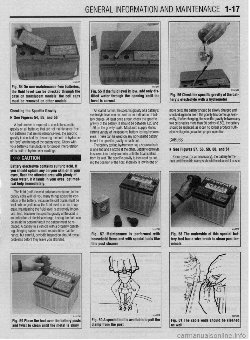
Fig. 54 On
non-maintenance-free
batteries,
the fluid level can be checked through the Fig. 55 If the fluid
level
is low, add only dis-
1 case on translucent models; the cell caps 1
must be removed on other models
1 1 tilled water through the opening until the
1 level is correct
Checking the Specific Gravity
A hydrometer is required to check the specific
# See Figures 54, 55, and 56
gravity on all batteries that are not maintenance-free.
On batteries that are maintenance-free, the soecific
gravity is checked by observing the built-in hydrome-
ter “eye” on the top of the battery case. Check with
your battery’s manufacturer for proper interpretation
of its built-in hvdrometer readinas. gravity of the battery. It should be between 1.20 and As stated earlier, the specific gravity of a battery’s
electrolyte level can be u
1.26 on the gravity scale. Most auto supply stores sed as an indication of bat-
tery charge. At least once
carry a variety of inexpensive battery testing hydrom- ? a year, check the specific
eters. These can be used on any non-sealed battery
, , , ,,
.,, . .
IO rest me specmc gravny in each cell.
The battery testing hydrometer has a squeeze bulb
at one end and a nozzle at the other. Battery electrolyte
the hydrometer until the float is lifted
-he specific gravity is then read by not-
n of the float. If gravity is low in one or mg tne posrtro
Battery electrolyte contains sulfuric acid. If
you should splash any on your skin or in your
eyes, flush the affected area with plenty of
clear water. If it lands in your eyes, get med-
ical help immediately.
The fluid (sulfuric acid solution) contained in the
battery cells will tell you many things about the con-
dition of the battery. Because the cell plates must be
kept submerged below the fluid level in order to op-
erate, maintaining the fluid level is extremely impor-
tant. And. because the soecific aravitv of the acid is
an indication of electrical charge, testing the fluid can
be an aid in determining if the battery must be re-
placed. A battery in a vehicle with a properly operat-
ing charging system should require little mainte-
nance, but careful, periodic inspection should reveal
problems before they leave you stranded. Fig. 57 Maintenance is performed with
Fig. 58 The underside of this special bat-
household items and with special tools like
tery tool has a wire brush to clean post ter-
I this post cleaner
I 1 minals Fig. 56 Check the specific gravity of the bat-
tery’s electrolyte with a hydrometer
more cells, the battery should be slowly charged and
Lhecked aqain to see if the aravitv has come
UP. Gen-
erally, if affer charging, the specific gravity between any
two cells varies more than 50 points (0.50) the battery
should be replaced, as it can no longer produce suffi-
cient voltage to guarantee proper operation.
CABLES
) See Figures 57, 56, 69, 60, and 61
Once a year (or as necessary), the battery termi-
nals and the cable clamps should be cleaned. Loosen
Page 49 of 408
.~ P.X I_ - “, .- I .-., IS ” .~.I .r
2-2 ENGINE ELECTRICAL
nn
ity and trouble: shooting electrical circuits,
please refer to Section 6 of this manual.
I
The ignition system on the 1.5L, 1993-96 1.8L,
2.OL SOHC, 1994-98 2.4L SOHC, 3.OL SOHC, and
3.5L engines uses a pointless type distributor, whose
advance mechanism is controlled by the Engine Con-
trol Unit (ECU). On the 1.5L, 1.8L, 2.4L and 3.5L en-
gines, the distributor houses a built in ignition coil
and ignition power transistor. The 2.8L SOHC and
3.OL SOHC engines utilize a separate coil and tran-
sister assemblv.
When the ignition switch is turned ON, battery
voltage is applied to the ignition coil primary winding.
As the shaft of the distributor rotates, signals are
transmitted from the oowertrain control module to the
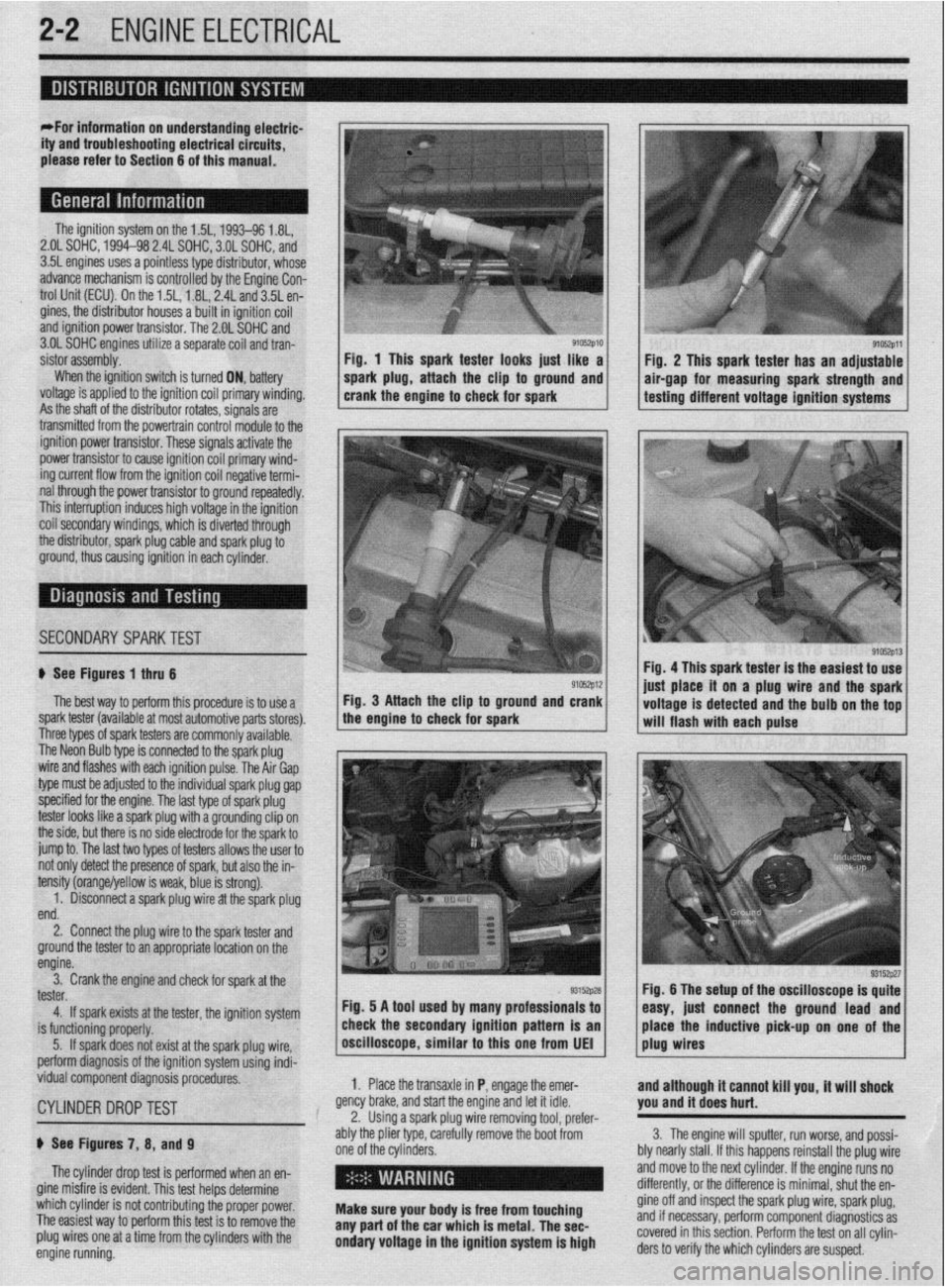
9105zp11 Fig. 1 This spark tester looks iust like a
Fiu. 2 This spark tester has an adjustable
spark plug, attach the clip to ground and air-gap for measuring spark strength and
crank the engine to check for spark testing different voltage ignition systems
.
ignition power trar rsistor. These signals activate the
power transistor to cause ignition coil primary wind-
ing current flow from the ignition coil negative termi-
nal through the power transistor to ground repeatedly.
This interruption induces high voltage in the ignition
coil secondarv windinas, which is diverted throuah
the distributor, spark plug cable and spark plug 6
ground, thus causing ignition in each cylinder.
I
SECONDARYSPARKTEST l;h.4-
! ,L ".~
'$ >,%
If See Figures 1 thru 6
91rJszp12 Fig. 4 This spark tester is the easiest to use
iust alace it on a plug wire and the spark
The best way to perform this procedure is to use a Fig. 3 Attach the clip to ground and crank
spark tester (available at most automotive parts stores). the engine to check for spark
I I voltage is detected and the bulb on the tof
-. will flash with each pulse
I nree types ot spark testers are commonly available.
The Neon Bulb type is connected to the spark plug
wire and flashes with each ignition pulse. The Air Gap
type must be adjusted to the individual spark plug gap
specified for the engine. The last type of spark plug
tester looks like a spark plug with a grounding clip on
the side, but there is no side electrode for the spark to
jump to. The last two types of testers allows the user to
not only detect the presence of spark, but also the in-
tensity (orange/yellow is weak, blue is strong).
1. Disconnect a spark plug wire at the spark plug
end.
2. Connect the plug wire to the spark tester and
ground the tester to an appropriate location on the
engine.
3. Crank the engine and check for spark at the
tester.
4. If spark exists at the tester, the ignition system
is functioning properly.
5. If spark does not exist at the spark plug wire,
perform diagnosis of the ignition system using indi-
vidual component diagnosis procedures,
CYLINDER DROPTEST
p See Figures 7, 8, and 9
The cylinder drop test is performed when an en-
gine misfire is evident. This test helps determine
which cylinder is not contributing the proper power.
The easiest way to perform this test is to remove the
plug wires one at a time from the cylinders with the
engine running. 1. Place the transaxle in P, engage the emer-
gency brake, and start the engine and let it idle.
2. Using a spark plug wire removing tool, prefer-
ably the plier type, carefully remove the boot from
one of the cylinders.
i ’
Make sure your body is free from touching
any part of the car which is metal. The sec-
ondary voltage in the ignition system is high and although it cannot kill you, it will shock
you and it does hurt.
3. The engine will sputter, run worse, and possi-
bly nearly stall. If this happens reinstall the plug wire
and move to the next cylinder. If the engine runs no
differently, or the difference is minimal, shut the en-
gine off and inspect the spark plug wire, spark plug,
and if necessary, perform component diagnostics as
covered in this section. Perform the test on all cylin-
ders to verify the which cylinders are suspect.
Page 61 of 408
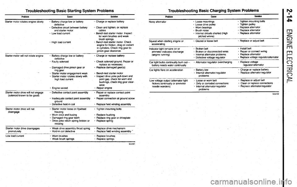
Troubleshooting Basic Starting System Problems Troubleshooting Basic Charging System Problems
Pmblem
Starter motor rotates engrne slowly cause
* Battery charge low or battery
defecttve Sobnlon
. Charge or replace battery
- Defective crrcurt between battery
and starter motor
* Low load current
* Hugh load current + Clean and ttghten, or replace
cables
* Bench-test starter motor Inspect
for wom brushes and weak
brush springs.
. Bench-test starter motor Check
engtne for fncbon, drag or coolant
rn cylinders. Check nng gear-to-
prnton gear clearance.
Starter motor wrll not rotate engrne
Starter motor dnve wrll not engage
(solenotd known to be good)
Starter motor dnve wtli not
dtsengage * Battery charge low or battery * Charge or replaoe battery
defecttve
* Faulty solenord . Check solenoid ground Reparr or
replace as necessary.
* Damaged drive pnron gear or * Replace damaged gear(s)
ring gear
* Starter motor engagement weak . Bench-test starter motor
. Starter motor rotates slowly wtth . Inspect dnve yoke pull-down and
high load current pornt gap, check for worn end
bushtngs. check m-g gear clear-
ance
. Engine setzed * Repatr engk7e
. Defecbve contact pant assembly * Reparr or replace contact pornt
assembly
. Inadequate contact pornt assembly + Repatr connectron at ground screw
ground
- Defeckve hold-In co11
* Replace field w~ndrng assembly
- Starter motor loose on flywheel . Ttghten mounttng bolts
houstng
. Worn drive end bustng . Replace bushtrg
* Damaged nng gear teeth . Replace ring gear or dnveplate
* Drive yoke return spnng broken or . Replace spnng
mtsstng
Starter motor dnve d&engages
prematurely
Low load current * Weak drive assembly thrust spnng * Replace dnve mechamsm
* Hold-tn co11 defeckve
. Replace field wtndtng assembly *
- Worn brushes . Replace brushes
* Weak brush springs * Replace spnngs Problem
Noisy alternator cause
* Loose mounbngs
. Loose drive pulley SoluIion
. Ttghten mountrng bolts
. Tighten pulley
. Worn beanngs
* Brush notse
* Internal circuits shorted (Hugh
pitched whrne) * Replace alternator
. Replace alternator
. Replace alternator
Squeal when starting engtne or . Glazed or loose belt * Replace or adfust belt
acceleratmg
Indicator light rematns on or . Broken belt . Install heft
ammeter rndrcates drscharge . Broken or dksconnected wares - Repatr or connect Waring
(ejrgrne runmng) * Internal aitemator problems * Replace alternator
. Defectrve voltage regulator . Replace vottage regulator/alternator
Car Irght bulbs contmually bum out- * Alternator/regulator overchargtng . Replace voltage
batter-v needs water conbnually regulatoriatternator
Car kghts flare on acceleratton . Battery low
. Internal alternator/regulator
problems * Charge or replace battery
. Replace alternator/regulator
Low voltage output (alternator lght
fltckers conbnually or ammeter
needle wanders) * Loose or worn belt
* Dkly or corroded connecttons
* Internal alternator/regulator
oroblems . Replace or adjust beit
. Clean or replace connecttons
* Replace alternator/regulator
Page 118 of 408
ENGINEANDENGINEOVERHAUL 3-57
Anything that generates heat and/or friction WIII
eventually burn or wear out (for example, a light bulb
generates heat, therefore its life span is limited). With
this in mind, a running engine generates tremendous
amounts of both; friction is encountered by the mov-
ing and rotating parts inside the engine and heat is
created by friction and combustion of the fuel How-
ever, the engine has systems designed to help reduce
the effects of heat and friction and provide added
longevrty. The oiling system reduces the amount of
friction encountered by the moving parts inside the
engine, while the cooling system reduces heat cre-
ated by friction and combustion If either system is
not maintained, a break-down will be inevitable.
Therefore, you can see how regular maintenance can
affect the service life of your vehicle, If you do not
drain, flush and refill your cooling system at the
proper intervals, deposits WIII begin to accumulate in
the radiator, thereby reducing the amount of heat it
can extract from the coolant The same applies to
your oil and filter; If it is not changed often enough it
becomes laden with contaminates and is unable to
properly lubricate the engine. This increases friction
and wear.
There are a number of methods for evaluating the
condition of your engine. A compression test can re-
veal the condition of your pistons, piston rings,
cylinder bores, head gasket(s), valves and valve
seats. An oil pressure test can warn you of possible
engine bearing, or oil pump failures. Excessrve oil
consumption, evidence of oil in the engine air intake
area and/or bluish smoke from the tailpipe may indi-
cate worn piston rings, worn valve guides and/or
valve seals. As a general rule, an engine that uses no
more than one quart of oil every 1000 miles is in
good condition. Engines that use one quart of oil or
more in less than 1000 miles should first be checked
for oil leaks. If any oil leaks are present, have them
fixed before determining how much oil is consumed
by the engine, especrally if blue smoke is not visible
at the tailpipe
COMPRESSION TEST
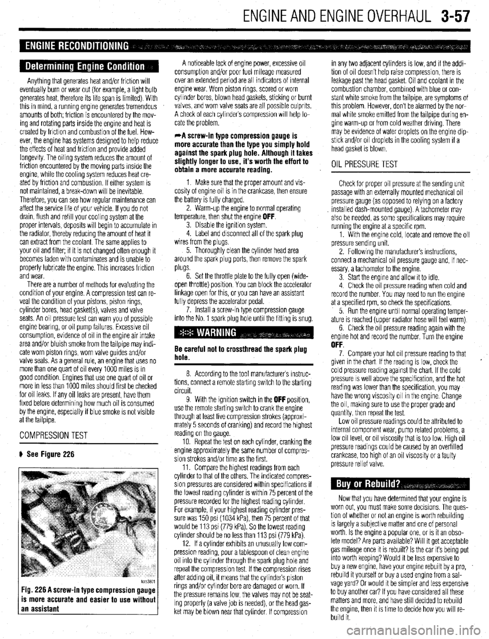
# See Figure 226
tccs3801 Fig. 226 A screw-in type compression gauge
is more accurate and easier to use without
an assistant
A noticeable lack of engine power, excessive oil
consumption and/or poor fuel mileage measured
over an extended period are all indicators of internal
engine wear. Worn piston rings, scored or worn
cylinder bores, blown head gaskets, sticking or burnt
valves, and worn valve seats are all possible culprits.
A check of each cylinders compression WIII help lo-
cate the problem.
*A screw-in type compression gauge is
more accurate than the type you simply hold
against the spark plug hole. Although it takes
slightly longer to use, it’s worth the effort to
obtain a more accurate reading.
1 Make sure that the proper amount and vis-
cosity of engine oil is in the crankcase, then ensure
the battery is fully charged.
2. Warm-up the engine to normal operating
temperature, then shut the engine
OFF. 3. Disable the ignition system.
4. Label and disconnect all of the spark plug
wires from the plugs,
5. Thoroughly clean the cylinder head area
around the spark plug ports, then remove the spark
plugs.
6. Set the throttle plate to the fully open (wide-
open throttle) position You can block the accelerator
linkage open for this, or you can have an assistant
fully depress the accelerator pedal.
7. Install a screw-in type compression gauge
into the No. 1 spark plug hole until the fitting is snug.
Be careful not to crossthread the spark plug
hole.
8. According to the tool manufacturers instruc-
tions, connect a remote starting switch to the starting
circuit.
9. With the ignition switch in the
OFF position,
use the remote starting switch to crank the engine
through at least five compression strokes (approxi-
mately 5 seconds of cranking) and record the highest
reading on the gauge
10. Repeat the test on each cylinder, cranking the
engine approximately the same number of compres-
sion strokes and/or time as the first.
11. Compare the hrghest readings from each
cylinder to that of the others. The indicated compres-
sion pressures are considered within specifications if
the lowest reading cylinder is within 75 percent of the
pressure recorded for the highest reading cylinder
For example, if your highest reading cylinder pres-
sure was 150 psi (1034 kPa), then 75 percent of that
would be 113 psi (779 kPa). So the lowest reading
cylinder should be no less than 113 psi (779 kPa).
12. If a cylinder exhibits an unusually low com-
pression reading, pour a tablespoon of clean engine
oil into the cylinder through the spark plug hole and
repeat the compression test. If the compression rises
after adding oil, it means that the cylinder’s piston
rings and/or cylinder bore are damaged or worn, If
the pressure remains low, the valves may not be seat-
ing properly (a valve job is needed), or the head gas-
ket may be blown near that cylinder. If compression in any two adjacent cylinders is low, and if the addi-
tion of oil doesn’t help raise compression, there is
leakage past the head gasket. Oil and coolant in the
combustion chamber, combined with blue or con-
stant white smoke from the tailpipe, are symptoms of
this problem. However, don’t be alarmed by the nor-
mal white smoke emitted from the tailpipe during en-
gine warm-up or from cold weather driving. There
may be evidence of water droplets on the engine dip-
stick and/or oil droplets in the cooling system if a
head gasket is blown.
OIL PRESSURETEST
Check for proper oil pressure at the sending unit
passage with an externally mounted mechanical oil
pressure gauge (as opposed to relying on a factory
Installed dash-mounted gauge). A tachometer may
also be needed, as some specifications may require
running the engine at a specific rpm.
1. With the engine cold, locate and remove the oil
pressure sending unit.
2. Followrng the manufacturers instructions,
connect a mechanical oil pressure gauge and, if nec-
essary, a tachometer to the engine.
3 Start the engine and allow it to idle.
4 Check the oil pressure reading when cold and
record the number. You may need to run the engine
at a specified rpm, so check the specifications,
5. Run the engine until normal operating temper-
ature is reached (upper radiator hose will feel warm)
6. Check the oil pressure reading again with the
engine hot and record the number. Turn the engine
OFF. 7. Compare your hot oil pressure reading to that
given in the chart If the reading is low, check the
cold pressure reading against the chart. If the cold
pressure IS well above the specification, and the hot
reading was lower than the specification, you may
have the wrong viscosity oil in the engine. Change
the oil, making sure to use the proper grade and
quantity, then repeat the test.
Low oil pressure readings could be attributed to
internal component wear, pump related problems, a
low oil level, or oil viscosity that is too low. High oil
pressure readings could be caused by an overfilled
crankcase, too htgh of an oil viscosity or a faulty
pressure relief valve.
Now that you have determined that your engine is
worn out, you must make some decisions. The ques-
tion of whether or not an engine IS worth rebuilding
is largely a subjective matter and one of personal
worth. Is the engine a popular one, or IS it an obso-
lete model? Are parts available? Will it get acceptable
gas mileage once It is rebuilt? Is the car its being put
into worth keeping? Would it be less expensive to
buy a new engine, have your engine rebuilt by a pro,
rebuild it yourself or buy a used engine from a sal-
vage yard? Or would It be simpler and less expensive
to buy another car? If you have considered all these
matters and more, and have still decided to rebuild
the engine, then it is time to decide how you will re-
build it.
Page 169 of 408
4-26 DRIVEABILITYAND EMISSIONS CONTROLS
The Powertrain Control Module (PCM) monitors
the signals of input and output sensors, some all the
time and others at certain times and processes each
signal. When the PCM notices that an irregularity has
continued for a specified time or longer from when
the irregular signal was initially monitored, the PCM
judges that a malfunction has occurred and will
memorize the malfunction code. The code is then
stored in the memory of the PCM and is accessible
through the data link (diagnostic connector) with the
use of an electronic scan tool or a voltmeter.
CHECK ENGINE/MALFUNCTION
INDICATOR LIGHT
Among the on-board diagnostic items, a check
engine/malfunction indicator light comes on to notify
the driver of a emission control component irregular-
ity. If the irregularity detected returns to normal or the
PCM judges that the component has returned to nor-
mal, the check engine/malfunction indicator light will
be turned off Moreover, if the ignition is turned OFF
and then the engine is restarted, the check
engine/malfunction indicator light will not be turned
on unttl a malfunction is detected.
The check engine/malfunction indicator light will
come on immediately after the ignition switch is
turned ON. The light should stay lit for 5 seconds
and then will go off. This Indicates that the check en-
gine/malfunction indicator lamp is operating nor-
mally. This does not signify a problem with the sys-
tem.
*The check engine/malfunction indicator
lamp will come on when the terminal for the
ignition timing adjustment is shorted to
ground. Therefore, it is not abnormal that the
light comes on even when the terminal for ig-
nition timing is shorted at time of ignition
timing adjustment.
To test the light, perform the following:
1. Turn the ignition switch ON. Inspect the check
engine/malfunction indicator lamp for Illumination.
2. The light should be lit for 5 seconds and then
should go out.
3. If the lamp does not illuminate, check for open
circuit In the harness, blown fuse or blown bulb.
SERVICE PRECAUTIONS
l Before attachrng or detaching the PCM harness
connectors, make sure the ignition switch is OFF and
the negative battery cable is disconnected to avoid
the possibility of damage to the PCM.
l When performing PCM input/output signal di-
agnosis, remove the pin terminal retainer from the
connectors to make it easier to insert tester probes
into the connector.
l When attaching or detaching pin connectors ,
from the PCM, take care not to bend or break any pin
terminals. Check that there are no bends or breaks on
PCM pin terminals before attempting any connec-
tions.
l Before replacing any PCM, perform the PCM
input/output signal diagnosis to make sure the PCM
is functioning properly.
l When measuring supply voltage of PCM-con-
trolled components with a circuit tester, separate 1
tester probe from another. If the 2 tester probes acci-
dentally make contact with each other during mea-
surement, a short circuit WIII result and damage the
PCM.
# See Figures 83
and 84
Remember that the diagnostic trouble code identi-
fication refers only to the circuit, not necessarily to a
specific component. For example, fault code 14 may
indicate an error in the throttle position sensor cir-
cuit; it does not necessarily mean the TPS sensor has
failed Testing of all related wiring, connectors and
the sensor itself may be required to locate the prob-
lem.
The PCM memory is capable of storing multiple
codes. During diagnosis the codes will be transmlt-
ted in numerical order from lowest to highest, regard-
less of the order of occurrence. If multiple codes are
stored, always begin diagnostic work with the lowest
numbered code
Make a note of the following:
1. When battery voltage IS low, no detection of
failure is possible. Be sure to check the battery volt-
age and other conditions before starting the test.
2. Diagnostic items are erased if the battery or the
engine controller connection is detached. Do not dis- connect either of these components until the diag-
nostic material present in the PCM has been read
completely.
3. Be sure to attach and detach the scan tool to
the data link connector with the ignition key OFF. If
the scan tool in connected or disconnected with the
ignition key ON, diagnostic trouble codes may be
falsely stored and the engine warning light may be il-
luminated. WITHASCANTOOL
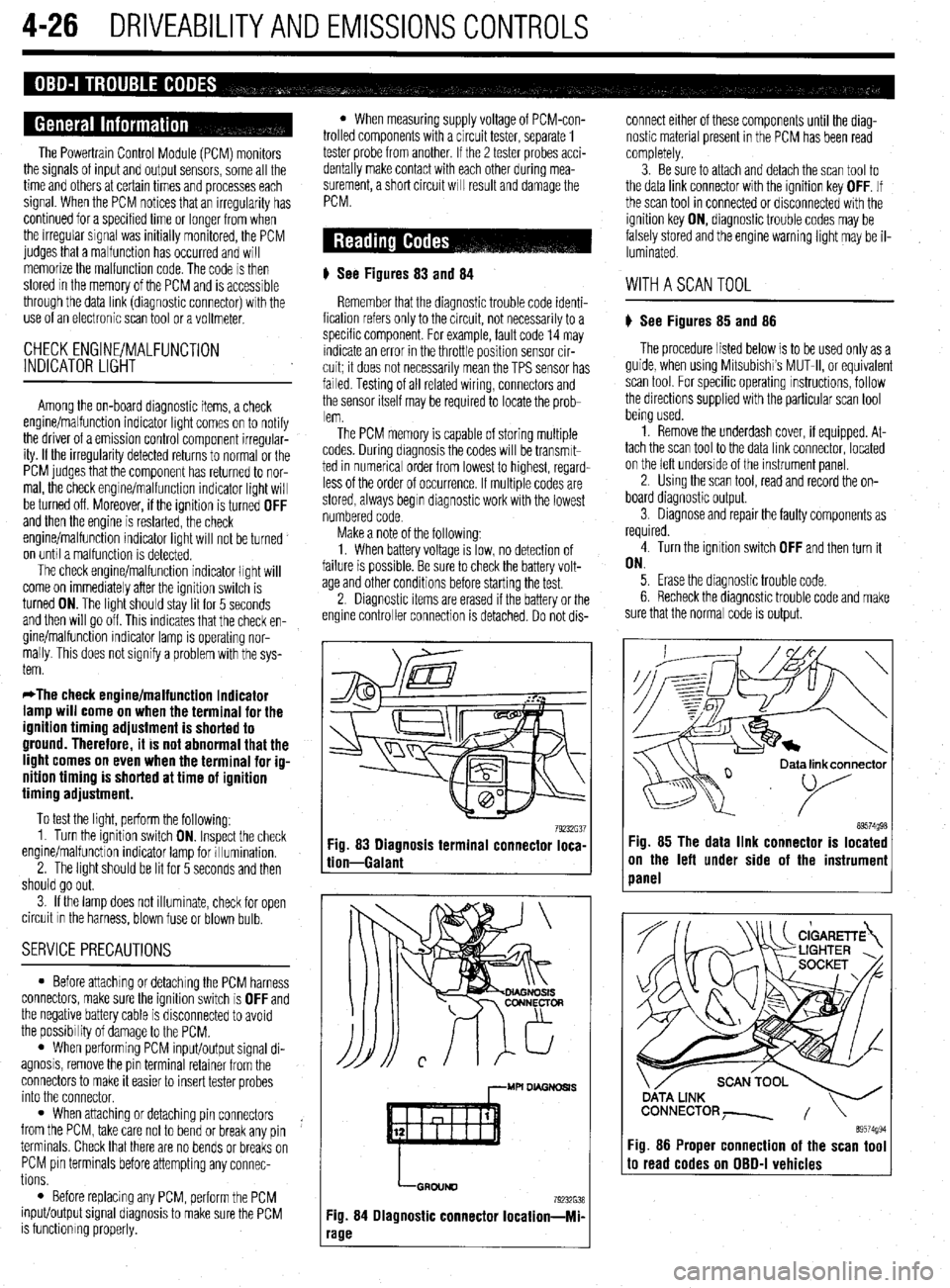
) See Figures 85 and 86
The procedure listed below is to be used only as a
guide, when using Mitsubishi’s MUT-II, or equivalent
scan tool. For specific operating instructions, follow
the directions supplied with the particular scan tool
bemg used.
1. Remove the underdash cover, if equipped. At-
tach the scan tool to the data link connector, located
on the left underside of the instrument panel.
2. Using the scan tool, read and record the on-
board diagnostic output.
3. Diagnose and repair the faulty components as
required
4. Turn the ignition switch OFF and then turn it
ON.
5. Erase the diagnostic trouble code.
6 Recheck the diaanostic trouble code and make
sure that the normal &de is output.
79232G37 89574g98 Fig. 83 Diagnosis terminal connector loca-
tion-Galant Fig. 85 The data link connector is located
on the left under side of the instrumeni
panel
,--MU DL4GNDSl.S
LGRDIJND
79232638
Fig. 84 Diagnostic connector Iocation-Mi-
‘age
ata link connector
89574994 Fig. 86 Proper connection of the scan tool to read codes on OBD-I vehicles
Page 205 of 408
6-2 CHASSIS ELECTRICAL
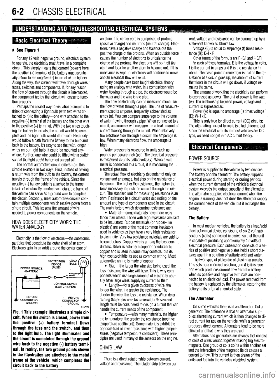
) See Figure 1
For any 12 volt, negative ground, electrical system
to operate, the electricity must travel in a complete
circurt. This simply means that current (power) from
the posibve (t) terminal of the battery must eventu-
ally return to the negative (-) terminal of the battery.
Along the way, this current will travel through wires,
fuses, switches and components. If, for any reason,
the flow of current through the circuit is interrupted,
the component fed by that circuit will cease to func-
tion properly.
Perhaps the easiest way to visualize a circuit is to
think of connecting a light bulb (with two wires at-
tached to it) to the battery-one wire attached to the
negative (-) terminal of the battery and the other wire
to the positive (t) terminal. With the two wires touch-
ing the battery terminals, the circuit would be com-
plete and the light bulb would illummate. Electricity
would follow a path from the battery to the bulb and
back to the battery. It’s easy to see that wrth longer
wires on our light bulb, it could be mounted any-
where. Further, one wire could be fitted with a switch
so that the light could be turned on and off.
The normal automotive circuit differs from this
simple example in two ways, Frrst, instead of having
a return wire from the bulb to the battery, the current
travels through the frame of the vehicle. Since the
negative (-) battery cable is attached to the frame
(made of electrically conductive metal), the frame of
the vehicle can serve as a ground wire to complete
the circuit. Secondly, most automotive circuits con-
tain multiple components which receive power from a
single circuit. This lessens the amount of wire
needed to power components on the vehicle.
HOW DOES ELECTRlClTYWORK:THE
WATER ANALOGY
Electricity is the flow of electrons-the subatomic
particles that constitute the outer shell of an atom.
Electrons spin in an orbit around the center core of
RETURN
RETURN
CONDUCTOR
CONDUCTOR
GROUND
GROUND
lccs2w
Fig. 1 This example illustrates a simple cir-
cuit. When the switch is closed, power from
the positive (t) battery terminal flows
through the fuse and the switch, and then
to the light bulb. The light illuminates and
the circuit is completed through the ground
wire back to the negative (-) battery termi-
nal. In reality, the two ground points shown
in the illustration are attached to the metal
frame of the vehicle, which completes the
circuit back to the battery
an atom The center core is comprised of protons
(positive charge) and neutrons (neutral charge). Elec-
trons have a negative charge and balance
out the
positive charge of the protons. When an outside force
causes the number of electrons to unbalance the
charge of the protons, the electrons will split off the
atom and look for another atom to balance out. If this
imbalance is kept up, electrons will continue to move
and an electrical flow will exist.
Many people have been taught electrical theory
using an analogy with water. In a comparison wrth
water flowing through a pipe, the electrons would be
the water and the wire is the pipe.
The flow of electricity can be measured much like
the flow of water through a pipe. The unit of measure-
ment used is amperes, frequently abbreviated as
amps (a). You can compare amperage to the volume
of water flowing through a pipe. When connected to a
circuit, an ammeter WIII measure the actual amount of
current flowing through the circuit. When relatively
few electrons flow through a circuit, the amperage is
low. When many electrons flow, the amperage is
high.
Water pressure is measured in units such as
pounds per square inch (psi); The electrical pressure
is measured in unrts called volts (v). When a volt-
meter is connected to a circuit, it is measuring the
electrical pressure.
The actual flow of electricity depends not only on
voltage and amperage, but also on the resistance of
the circuit The higher the resistance, the higher the
force necessary to push the current through the cir-
cuit. The standard unit for measuring resistance is an
ohm. Resistance in a crrcuit varies dependmg on the
amount and type of components used in the circuit.
The main factors which determine resistance are:
l Material-some materials have more resis-
tance than others Those with high resistance are said
to be insulators Rubber materials (or rubber-like
plashcs) are some of the most common insulators
used in vehicles as they have a very high resistance
to electricity Very low resistance materials are said to
be conductors. Copper wire is among the best con-
ductors. Silver is actually a superior conductor to
copper and is used in some relay contacts, but its
high cost prohibits its use as common wiring Most
automotive wiring is made of copper.
l Size-the larger the wire size being used, the
less resistance the wire will have. This IS why com-
ponents which use large amounts of electricity usu-
ally have large wires supplying current to them.
l Length-for a given thickness of wire, the
longer the wire, the greater the resistance. The
shorter the wire, the less the resistance. When deter-
mining the proper wire for a circuit, both size and
length must be considered to design a circuit that can
handle the current needs of the component.
l Temperature-with many materials, the higher
the temperature, the greater the resistance (positive
temperature coefficient). Some materials exhibit the
opposite trait of lower resistance with higher temper-
atures (negative temperature coefficient). These prin-
ciples are used in many of the sensors on the engine
OHM'S LAW
There is a direct relationship between current,
voltage and resistance. The relationship between cur- rent, voltage and resistance can be summed up by a
statement known as Ohm’s law.
Voltage (E) is equal to amperage (I) times resis-
tance (R): E=l x R
Other forms of the formula are R=E/I and I=E/R
In each of these formulas, E is the voltage in volts,
I is the current in amps and R IS the resistance in
ohms. The basic point to remember is that as the re-
sistance of a circuit goes up, the amount of current
that flows in the circuit will go down, if voltage re-
mains the same.
The amount of work that the electricity can perform
is expressed as power. The unit of power is the watt
(w). The relationship between power, voltage and
current
IS expressed as:
Power(w) is equal to amperage (I) times voltage
(E): W=l x E
This is only true for direct current (DC) circuits:
The alternating current formula is a tad different, but
since the electrical circuits in most vehicles are DC
type, we need not get into AC circuit theory.
POWERSOURCE
Power is supplied to the vehicle by two devices:
The battery and the alternator. The battery supplies
electrical power during starting or during periods
when the current demand of the vehicle’s electrical
system exceeds the output capacity of the alternator.
The alternator supplies electrical current when the
engine is running
Just not does the alternator supply
the current needs of the vehicle, but it recharges the
battery.
The Battery
In most modern vehicles, the battery is a lead/acid
electrochemical device consisting of six 2 volt sub-
sections (cells) connected in series, so that the unit
is capable of producing approximately 12 volts of
electrical pressure. Each subsection consists of a se-
ries of positive and negative plates held a short dis-
tance apart in a solutron of sulfuric acid and water.
The two types of plates are of dissimilar metals,
This sets up a chemrcal reaction, and it is this reac-
tion which produces current flow from the battery
when Its positive and negattve terminals are con-
nected to an electrical load. The power removed from
the battery is replaced by the alternator, restoring the
battery to its original chemical state.
The Alternator
On some vehicles there isn’t an alternator, but a
generator. The difference IS that an alternator sup-
plies alternating current which is then changed to di-
rect current for
use on the vehicle, while a generator
produces direct current. Alternators tend to be more
efficient and that is why they are used.
Alternators and generators are devices that consist
of coils of wires wound together making big electro-
magnets. One group of coils spins within another set
and the interaction of the magnetic fields causes a
current to flow. This current is then drawn off the
coils and fed into the vehicles electrical system.
Page 222 of 408
CHASSIS ELECTRICAL 6-19
1. Disconnect the negative battery cable.
are all built into 1 multi-function combination
2. Remove the instrument cluster, as outlined 1. Disconnect the negative battery cable.
earlier in this section. switch that is mounted on the steering col-
2. Using a small screwdriver or other suitable
umn. Refer to Section 8 for procedures re-
3. Remove the retaining screws for the instrument tool, carefully pry the retaining clips from either side
garding the combination switch.
cluster lens and cover assembly. Remove the cover of the switch trim plate.
3.
and lens. Carefully pull the switch and trim plate out of
,
4. Remove the retaining screws for the gauge or the instrument panel.
4. Detach the electrical connectors and remove
warning lamp to be replaced, then remove the gauge
the switch.
or warning lamp.
REMOVAL&INSTALLATION : 5. The installation is the reverse of removal.
To install:
5. Place the gauge or warning lamp into place
and tighten the retaining screws. 1. Disconnect the negative battery cable.
6. Install the instrument cluster lens and cover 2. Using a suitable prytool, disengage the switch
assembly. retaining tabs.
REMOVAL &INSTALLATION 7. Install the instrument cluster. 3. Gently pull the switch from the instrument
8. Connect the negative battery cable. panel.
4. Detach the electrical connector and remove the *On all models the headlights, turn signals,
switch. and on some models, the cruise control func-
5. The installation is the reverse of removal. tion are all built into 1 multi-function combi-
nation switch that is mounted on the steerinq
REMOVAL &INSTALLATION column. Refer to Section 8 for procedures 6
garding the combination switch.
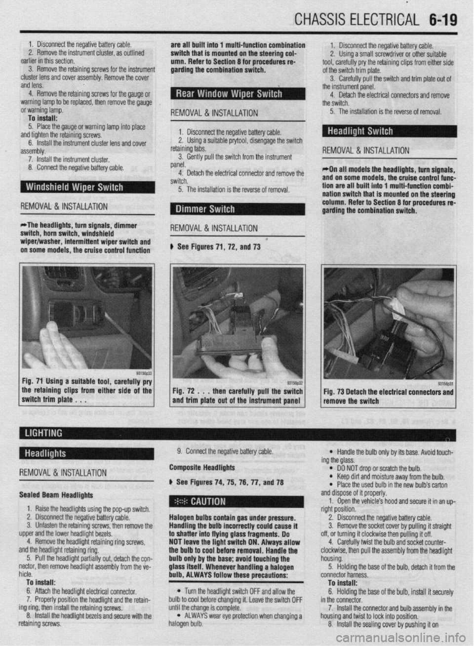
*The headlights, turn signals, dimmer
switch, horn switch, windshield
REMOVAL &INSTALLATION
wiper/washer, intermittent wiper switch and *
on some models, the cruise control function # See Figures 71, 72, and 73
the retaining clips from either side of the
switch trim plate . . . Fig. 72 . . . then carefully pull the switch
and trim plate out of the instrument panel Fig. 73 Detach the electrical connectors and
remove the switch
-
REMOVAL &INSTALLATION
Sealed Beam Headlights
1. Raise the headlights using the pop-up switch.
2. Disconnect the negative battery cable.
3. Unfasten the retaining screws, then remove the
upper and the lower headlight bezels.
4. Remove the headlight retaining ring screws,
and the headlight retaining ring.
5. Pull the headlight partially out, detach the con-
nectar, then remove headlight assembly from the ve-
hicle.
To install:
6. Attach the headlight electrical connector.
7. Properly position the headlight and the retain-
ing ring, then install the retaining screws.
8. Install the headlight bezels and secure with the
retaining screws. 9. Connect the negative battery cable.
Composite Headlights
6 See Figures 74, 75, 76, 77, anU78
Halogen bulbs contain gas under pressure.
Handling the
bulb incorrectly could cause it
to shatter into flying glass fragments. Do
NOT leave the light switch ON. Always allow
the bulb to cool before removal. Handle the
bulb only by the base; avoid touching the
glass itself. Whenever handling a halogen
bulb, ALWAYS follow these precautions:
l Turn the headlight switch OFF and allow the
bulb to cool before changing it. Leave the switch OFF
until the change is complete.
l ALWAYS wear eye protection when changing a
halogen bulb.
l Handle the bulb only by its base. Avoid touch-
ing the glass.
l DO NOT drop or scratch the bulb. l Keep dirt and moisture away from the bulb.
* Place the used bulb in the new bulb’s carton
and dispose of it properly.
1. Open the vehicle’s hood and secure it in an up-
right position.
2. Disconnect the negative battery cable.
3. Remove the socket cover by pulling it straight
off, or turning it clockwise then pulling it off.
4. Carefully twist the bulb and socket counter-
clockwise, then pull the assembly from the headlight
housing.
5. Holding the base of the bulb, detach it from the
connector harness.
To install:
6. Holding the base of the bulb, install it securely
in the connector.
7. Install the connector and bulb assembly in the
housing and twist to lock into position.
8. Install the sealing cover by pushing it on
Page 223 of 408
.
6-20 CHASSIS ELECTRICAL
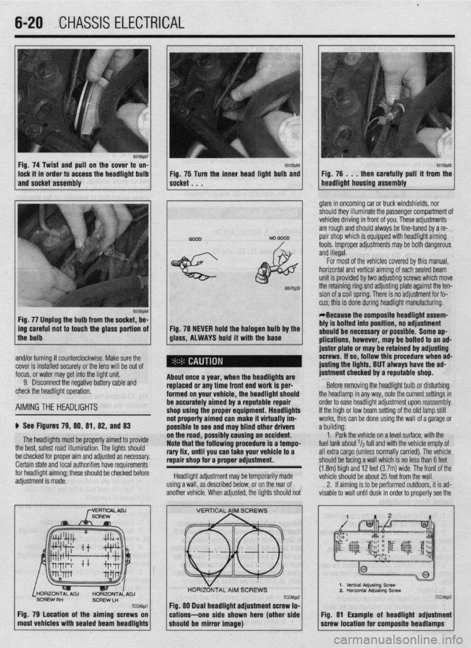
Fig. 74 Twist and pull on the cover to un-
lock it in order to access the headlight bulb
and socket assembly 93Mm Fig, 75 Turn the inner head light bulb and then carefully pull’ it from the
NO 0000 . glare in oncoming car or truck windshields, nor
should they illuminate the passenger compartment of
vehicles driving in front of you. These adjustments
are rough and should always be fine-tuned by a re-
pair shop which is equipped with headlight aiming
tools. Improper adjustments may be both dangerous
and illegal.
Fig. 77 Unplug the bulb from the socket, be-
L
ing careful not to touch the glass portion of
the bulb
I
6957Q39
Fig. 78 NEVER hold the halogen bulb by the
glass, ALWAYS hold it with the base
,
About once a year, when the headllgftts are
replaced or any time front end work is per-
formed on your vehicle, the headlight should
be accurately aimed by a reputable repair
shop uslng the proper equipment. Headlights
not properly aimed can make it virtually im-
possible to see ar Id may blind other drivers
ibly causing an accident.
Note that the’following procedure is a tempo-
rary fix, until you can take your vehicle to a
repair shop for a proper adjustment.
Headlight adjustment may be temporarily made
using a wall, as described below, or on the rear of
another vehicle. When adjusted, the lights should not For most of the vehicles covered by this manual,
horizontal and vertical aiming of eachsealed beam
unit is provided by two adjusting screws which move
the retaining ring and adjusting plate against the ten-
sion of a coil spring. There is no adjustment for fo-
cus; this is done during headlight manufacturing.
*Because the composite headlight assem-
bly is bolted into position, no adjustment
should be necessary or possible. Some ap-
plications, however, may be bolted to an ad-
juster plate or may be retained by adjusting
screws. If so, follow this procedure when ad-
@sting the lights, BUT always have the ad-
justment checked by a reputable shop.
Before removing the headlight bulb or disturbing
the headlamp in any way, note the current settings in
order to ease headlight adjustment upon reassembly.
If the high or low beam setting of the old lamp still
works, this can be done using the wall of a garage or
a building:
1. Park the vehicle on a level surface, with the
fuel tank about r/a full and with the vehicle empty of
all extra cargo (unless normally carried). The vehicle
should be facing a wall which is no less than 6 feet
(1.8m) high and 12 feet (3.7m) wide. The front of the
vehicle should be about 25 feet from the wall.
2. If aiming is to be performed outdoors, it is ad-
visable to wait until dusk in order to properly see the
% and/or turning it counterclockwise. Make sure the
cover is installed securely or the lens will be out of
focus, or water may get into the light unit.
9. Disconnect the negative battery cable and
check the headlight operation.
AIMINGTHE HEADLIGHTS
$ See Figures 79, 88, 81, 82, and 83
The headlights must be proper’ ’ ’ ’
the best, safest road illumination. ’ ’
ly armea IO provrae
The lights should
:.__1__1 __ - -___-_-. on the road, POSSI
be checked for proper aim and adfusreu as IlweSYdly. Certain state and local authorities have requirements
for headlight aiming; these should be checked before
adjustment is made.
SCFEWRH
ScFlEwLn
TCcAssa
Fig. 79 Location of the aiming screws on
most vehicles with sealed beam headlights
TCCAE@ Fig. 88 Dual headlight adjustment screw lo-
cations--one side shown here (other side
should be mirror image)
2.
TCC&z3
Fig. 81 Example of headlight adjustment
screw location for composite headlamps