1900 MITSUBISHI DIAMANTE wiring diagram
[x] Cancel search: wiring diagramPage 23 of 408
l-24 GENERALINFORMATIONAND MAINTENANCE
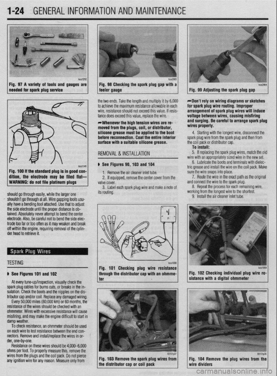
b%slZl2 Fig. 97 A variety of tools and gauges are
needed for spark plug service tm2903 Fig. 98 Checking the spark plug @au with a tccs2904 feeler gauge. - Fig. 99 Adjusting the spark plug gap
ig. 100 If the standard plug Is in good con-
ftlon, the electrode may be filed flat- the two ends. Take the length and multiply it by 6,000
to achieve the maximum resistance allowable in each
wire, resistance should not exceed this value. If resis-
tance does exceed this value, replace the wire.
*Whenever the high tension wires are re- ’
moved from the plugs, coil, or distributor,
silicone grease must be applied to the boot
before reconnection. Coat the entire Interior
surface with a suitable silicone grease.
REMOVAL &INSTALLATION
# See Figures 90,103 and 104
1. Remove the air cleaner inlet tube.
2. If eouiooed, remove the center cover from the
WARNING: do not file platinum plugs
valve covei.
3. Label each spark plug wire and make a note of
should go through easily, while the larger one its routing.
I’ shouldn’t go through at all. Wire gapping tools usu-
ally have a bending tool attached. Use that to adjust
the side electrode until the proper distance is ob-
tained. Absolutely never attempt to bend the center
electrode. Also, be careful not to bend the side elec- *Don’t rely on wiring diagrams or sketches
for spark plug wire routing. Improper
arrangement of spark plug wires will induce
voltage between wires, causing misfiring
and surging. Be careful to arrange spark plug
wires properly.
4. Starting with the longest wire, disconnect the
spark plug wire from the spark plug and then from
the coil pack or distributor cap.
To install:
5. If replacing the spark plug wires, match the olc
wire with an appropriately sized wire in the new set.
6. Lubricate the boots and terminals with dielec-
tric grease and install the wire on the coil pack. Make
sure the wire snaps into place.
a 7. Route the wire in the exact path as the original
nd connect the wire to the spark plug.
8. Repeat the process for each remaining wire,
iorking from the longest wire to the shortest.
9. Install the air cleaner inlet tube.
trode too far or too often as it may weaken and break
off within the engine, requiring removal of the cylin-
der head to retrieve it.
TESTING
# See Figures 191 and 102
At every tune-up/inspection, visually check the
spark plug cables for burns cuts, or breaks in the in-
sulation. Check the boots and the nipples on the dis-
tributor cap and/or coil. Replace any damaged wiring.
Every 50,000 miles (80,000 km) or 60 months, the
resistance of the wires should be checked with an
ohmmeter. Wires with excessive resistance will cause
misfiring, and may make the engine difficult to start in
damp weather.
To check resistance, an ohmmeter should be used ’
on each wire to test resistance between the end con-
nectors. Remove and install/replace the wires in or- ’
der, one-by-one.
Resistance on these wires should be 4,000-6,000
ohms per foot. To properly measure this, remove the
wires from the plugs and the coil pack. Do not pierce
any ignition wire for any reason. Measure only from Fig. 103 Remove the spark plug wires from
tcG1009 Fig. 102 Checking individual plug wire re-
sistance with a digital ohmmeter
Fig. 104 Remove the plug wires from the
wire dividers
Page 204 of 408
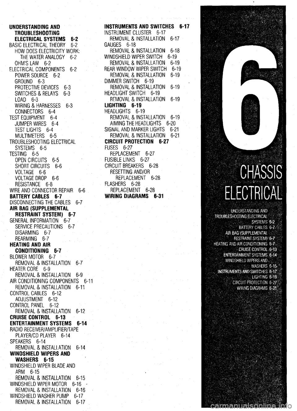
UNDERSTANDING AND
TROUBLESHOOTING
ELECTRICAL SYSTEMS 6-2
BASIC ELECTRICALTHEORY 6-2
HOW DOES ELECTRICITY WORK:
THEWATERANALOGY 6-2
OHM'S LAW 6-2
ELECTRICALCOMPONENTS 6-2
POWERSOURCE 6-2
GROUND 6-3
PROTECTIVE DEVICES 6-3
SWITCHES&RELAYS 6-3
LOAD 6-3
WIRING & HARNESSES 6-3
CONNECTORS 6-4
TEST EQUIPMENT 6-4
JUMPER WIRES 6-4
TEST LIGHTS 6-4
MULTIMETERS 6-5
TROUBLESHOOTING ELECTRICAL
SYSTEMS 6-5
TESTING 6-5
OPEN CIRCUITS 6-5
SHORT CIRCUITS 6-6
VOLTAGE 6-6
VOLTAGE DROP 6-6
RESISTANCE 6-8
WIRE AND CONNECTORREPAIR 6-6
BATTERY CABLES 6-7
DISCONNECTING THE CABLES 6-7
AIR BAG (SUPPLEMENTAL
RESTRAINT SYSTEM) 6-7
GENERALINFORMATION 6-7
SERVICE PRECAUTIONS 6-7
DISARMING 6-7
REARMING 6-7
HEATING AND AIR
CONDITIONING 6-7
BLOWER MOTOR 6-7
REMOVAL &INSTALLATION 6-7
HEATER CORE 6-9 INSTRUMENTS AND SWITCHES 6-17
INSTRUMENTCLUSTER 6-17
REMOVAL &INSTALLATION 6-17
GAUGES 6-18
REMOVAL&INSTALLATION 6-18
WINDSHIELD WIPER SWITCH 6-19
REMOVAL&INSTALLATION 6-19
REARWINDOWWIPERSWITCH 6-19
REMOVAL &INSTALLATION 6-19
DIMMER SWITCH 6-19
REMOVAL & INSTALLATION 6-19 .
HEADLIGHT SWITCH 6-19
REMOVAL & INSTALLATION 6-19
LIGHTING 6-19
HEADLIGHTS 6-19
REMOVAL &INSTALLATION 6-19
AIMINGTHEHEADLIGHTS 6-20
SIGNAL AND MARKER LIGHTS 6-21
REMOVAL &INSTALLATION 6-21
CIRCUIT PROTECTION 6-27
FUSES 6-27
REPLACEMENT 6-27
FUSIBLE LINKS 6-27
CIRCUIT BREAKERS 6-28
RESETTING AND/OR
REPLACEMENT 6-28
FLASHERS 6-28
REPLACEMENT 6-28
WIRING DIAGRAMS 6-31
REMOVAL & INSTALLATION 6-9
AIR CONDITIONING COMPONENTS 6-11
REMOVAL & INSTALLATION 6-11
CONTROLCABLES 6-12
ADJUSTMENT 6-12
CONTROL PANEL 6-12
REMOVAL & INSTALLATION 6-12
CRUISE CONTROL 6-13
ENTERTAINMENT SYSTEMS 6-14
RADIO RECEIVER/AMPLIFIER/TAPE
PLAYER/CD PLAYER 6-14
SPEAKERS 6-14
REMOVAL & INSTALLATION 6-14
WINDSHIELD WIPERS AND
WASHERS 6-15
WINDSHIELD WIPER BLADE AND
ARM 6-15
REMOVAL & INSTALLATION 6-15
WINDSHIELD WIPER MOTOR 6-16 _
REMOVAL &INSTALLATION 6-16
WINDSHIELD WASHER PUMP 6-17
REMOVAL &INSTALLATION 6-17
Page 234 of 408
CHASSIS ELECTRICAL 6-31
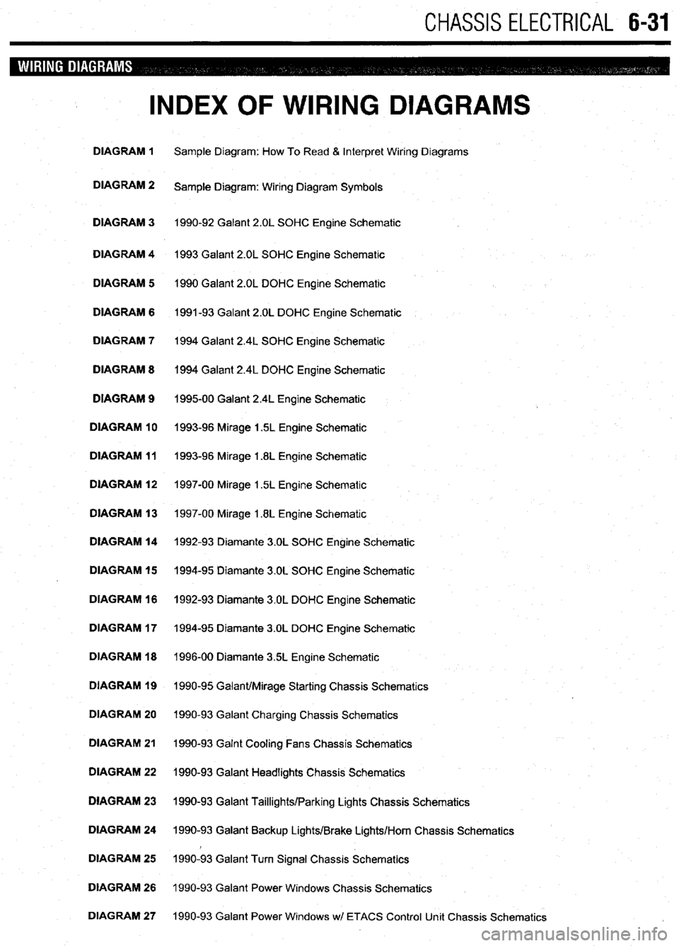
INDEX OF WIRING DIAGRAMS
DIAGRAM 1 Sample Diagram: How To Read & Interpret Wiring Diagrams
DIAGRAM 2
Sample Diagram: Wiring Diagram Symbols
DIAGRAM 3 1990-92 Galant 2.OL SOHC Engine Schematic
DIAGRAM 4 1993 Galant 2.OL SOHC Engine Schematic
DIAGRAM 5 1990 Galant 2.OL DOHC Engine Schematic
DIAGRAM 6 1991-93 Galant 2.OL DOHC Engine Schematic
DIAGRAM 7 1994 Galant 2.4L SOHC Engine Schematic
DIAGRAM 8 1994 Galant 2.4L DOHC Engine Schematic
DIAGRAM 9
199500 Galant 2.4L Engine Schematic
DIAGRAM 10 1993-96 Mirage 1.5L Engine Schematic
DIAGRAM 11 1993-96 Mirage 1.8L Engine Schematic
DIAGRAM 12 1997-00 Mirage 1.5L Engine Schematic
DIAGRAM 13 1997-00 Mirage 1.8L Engine Schematic
DIAGRAM 14 1992-93 Diamante 3.OL SOHC Engine Schematic
DIAGRAM 15 1994-95 Diamante 3.OL SOHC Engine Schematic
DIAGRAM 16 1992-93 Diamante 3.OL DOHC Engine Schematic
DIAGRAM 17 1994-95 Diamante 3.OL DOHC Engine Schematic
DIAGRAM 18 1996-00 Diamante 35L Engine Schematic
DIAGRAM 19 1990-95 Galant/Mirage Starting Chassis Schematics
DIAGRAM 20 1990-93 Galant Charging Chassis Schematics
DIAGRAM 21 1990-93 Galnt Cooling Fans Chassis Schematics
DIAGRAM 22 1990-93 Galant Headlights Chassis Schematics
DIAGRAM 23 1990-93 Galant Taillights/Parking Lights Chassis Schematics
DIAGRAM 24 1990-93 Galant Backup Lights/Brake Lights/Horn Chassis Schematics
DIAGRAM 25 1990-93 Galant Turn Signal Chassis Schematics
DIAGRAM 26 1990-93 Galant Power Windows Chassis Schematics
DIAGRAM 27 1990-93 Galant Power Windows wl ETACS Control Unit Chassis Schematics
Page 235 of 408
6-32 CHASSIS ELECTRICAL
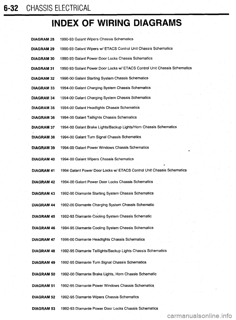
INDEX OF WIRING DIAGRAMS
DIAGRAM 28 1990-93 Galant Wipers Chassis Schematics
DIAGRAM 29 1990-93 Galant Wipers w/ ETACS Control Unit Chassis Schematics
DIAGRAM 30 1990-93 Galant Power Door Locks Chassis Schematics
DIAGRAM 31 1990-93 Galant Power Door Locks wl ETACS Control Unit Chassis Schematics
DIAGRAM 32 1996-00 Galant Starting System Chassis Schematics
DIAGRAM 33 1994-00 Galant Charging System Chassis Schematics
DIAGRAM 34 1994-00 Galant Charging System Chassis Schematics
DIAGRAM 35 1994-00 Galant Headlights Chassis Schematics
DIAGRAM 36 1994-00 Galant Taillights Chassis Schematics
DIAGRAM 37 1994-00 Galant Brake Lights/Backup Lights/Horn Chassis Schematics
DIAGRAM 38 1994-00 Galant Turn Signal Chassis Schematics
DIAGRAM 39 1994-00 Galant Power Windows Chassis Schematics
m
DIAGRAM 40 1994-00 Galant Wipers Chassis Schematics
b
DIAGRAM 41 1994 Galant Power Door Locks w/ ETACS Control Unit Chassis Schematics
DIAGRAM 42 1994-00 Galant Power Door Locks Chassis Schematics
DIAGRAM 43 1992-00 Diamante Starting System Chassis Schematics
DIAGRAM 44 1992-00 Diamante Charging System Chassis Schematic
DIAGRAM 45 1992-93 Diamante Cabling System Chassis Schematic
DIAGRAM 46 1994-95 Diamante Cooling System Chassis Schematics
DIAGRAM 47 1996-00 Diamante Headlights Chassis Schematics
DIAGRAM 48 1992-95 Diamante Taillights/Backup Lights Chassis Schematics
DIAGRAM 49 1992-95 Diamante Turn Signal Chassis Schematics
DIAGRAM 50 1992-00 Diamante Brake Lights, Horn Chassis Schematic
DIAGRAM 51 1992-95 Diamante Power Windows Chassis Schematics
DIAGRAM 52 1992-95 Diamante Wipers Chassis Schematics
DIAGRAM 53 1992-93 Diamante Power Door Locks Chassis Schematics
Page 236 of 408
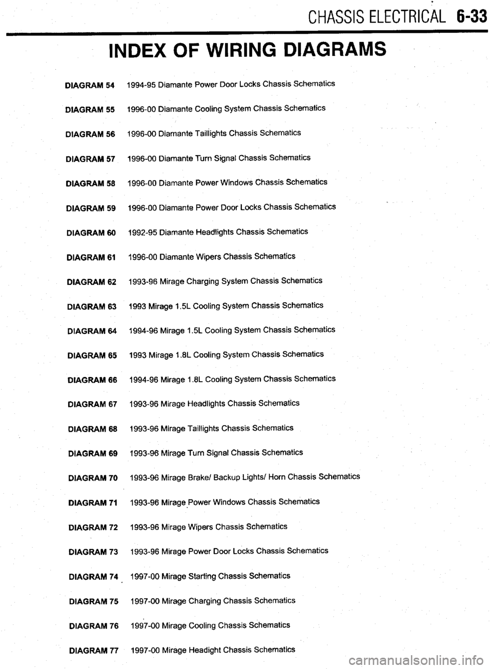
CHASSIS ELECTRlCiL 6-33
INDEX OF WIRING DIAGRAMS
DIAGRAM 54
DIAGRAM 55
DIAGRAM 56
DIAGRAM 57
DIAGRAM 58
DIAGRAM 59
DIAGRAM 60
DIAGRAM 61
DIAGRAM 62
DIAGRAM 63
DIAGRAM 64
DIAGRAM 65
DIAGRAM 66
DIAGRAM 67
DIAGRAM 68
DIAGRAM 69
DIAGRAM 70
DIAGRAM 71
DIAGRAM 72
DIAGRAM 73
DIAGRAM 74
DIAGRAM 75
DIAGRAM 76
DIAGRAM 77 1994-95 Diamante Power Door Locks Chassis Schematics
1996-00 Diamante Cooling System Chassis Schematics
1996-00 Diamante Taillights Chassis Schematics
1996-00 Diamante Turn Signal Chassis Schematics
1996-00 Diamante Power Windows Chassis Schematics
1996-00 Diamante Power Door Locks Chassis Schematics
1992-95 Diamante Headlights Chassis Schematics
1996-00 Diamante Wipers Chassis Schematics
1993-96 Mirage Charging System Chassis Schematics
1993 Mirage 1.5L Cooling System Chassis Schematics
1994-96 Mirage 1.5L Cooling System Chassis Schematics
1993 Mirage 1.8L Cooling System Chassis Schematics
1994-96 Mirage 1.8L Cooling System Chassis Schematics
1993-96 Mirage Headlights Chassis Schematics
1993-96 Mirage Taillights Chassis Schematics
1993-96 Mirage Turn Signal Chassis Schematics
1993-96 Mirage Brake/ Backup Lights/ Horn Chassis Schematics
1993-98 Mirage-Power Windows Chassis Schematics
1993-96 Mirage Wipers Chassis Schematics
1993-96 Mirage Power Door Locks Chassis Schematics
1997-00 Mirage Starting Chassis Schematics
1997-00 Mirage Charging Chassis Schematics
1997-00 Mirage Cooling Chassis Schematics
1997-00 Mirage Headight Chassis Schematics
Page 237 of 408
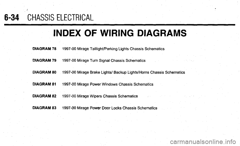
6-34 CHASSIS ELECTRICAL
INDEX OF WIRING DIAGRAMS
DIAGRAM 78 1997-00 Mirage Taillight/Parking Lights Chassis Schematics
DIAGRAM 79
1997-00 Mirage Turn Signal Chassis Schematics
DIAGRAM 80 1997-00 Mirage Brake Lights/ Backup Lights/Horns Chassis Schematics
DIAGRAM 81
1997-00 Mirage Power Windows Chassis Schematics
DIAGRAM 82 1997-00 Mirage Wipers Chassis Schematics
DIAGRAM 83 1997-00 Mirage Power Door Locks Chassis Schematics
Page 238 of 408
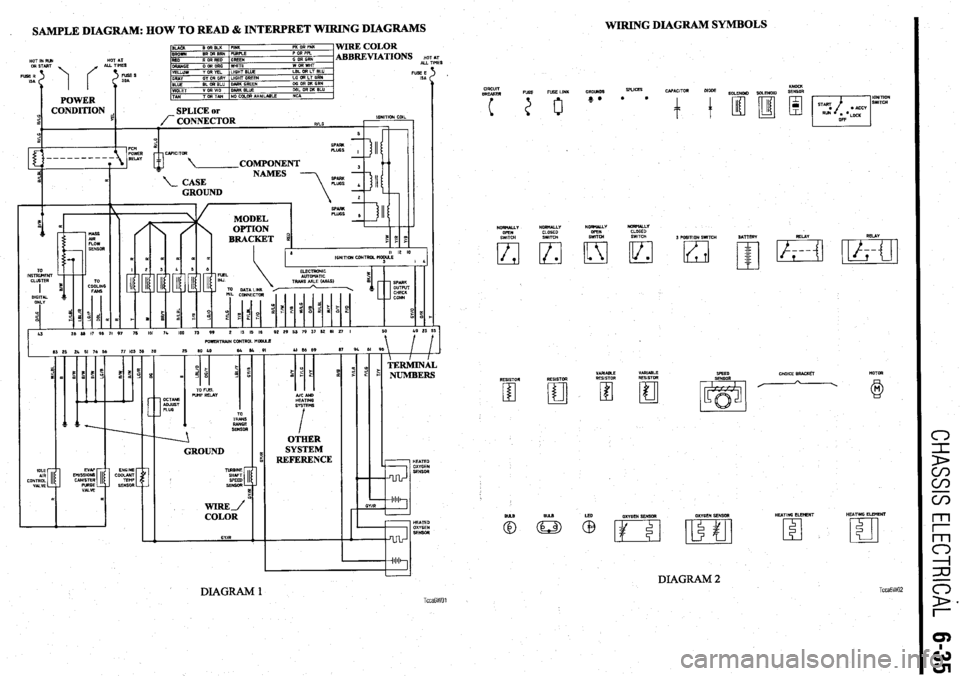
WIRING DIAGRAM SYMBOLS
. SAMPLE DIAGRAM: HOW TO READ & INTERPRET WIRING DIAGRAMS
c-l
1
D
m
m
WIRE COLOR
ABBREVIATIONS HO ALL TI’
TIM
FUSEE
ISA HOT IN RIM HOT AT r
ES
CIRCUIT
BREAKER
1 i ‘=iT KNOCK
SOLENOID SOLENOID SENSOR
3 POSITION SWITCH NORNALLY NORMALLY
NORHbUY
OPEN
SWITCH
El
RESISTOR
m NORMALLY
CLOSED
SWITCH
lzl l
RESISTOR
El SATTERY REIAY RELAY
WIWIZRTIWN CONTROL HODUsE
AICAND
HEATING
SYSTEMS
I
OTHER
SYSTEM
REFERENCE
CHOKE RRACKh MOTOR
VARIABLE VARIABLE
RESISTOR RESISTOR WEED
SENSOR
A
/
GROUND HEATED
IdI1
GYlR
m OXYGEN SENSOR HEATING ELEHENT HEATING ELEMENT
‘m
c3
DIAGRAM 2 TccaGW02 DIAGRAM 1 TccaGWOl
Page 395 of 408
TROUBLESHOOTING 11-13
NOTE: When one shock fails, ft is recommended to replace front or rear
units as pairs.
3. Vehicle leans excessively in turns
a. Check for worn or leaking shock absorbers or strut assemblies and replace as neces-
sary.
b. Check for missing, damaged, or worn stabilizer links or bushings, and replace or in-
stall as necessary.
4. Vehicle ride quality seems excessively ha&h
a. Check for seized shock absorbers or strut assemblies and replace as necessary.
b. Check for excessively high tire pressures and adjust pressures to vehicle recommen-
dations.
5. Vehicle seems low or leans to one side
a. Check for a damaged, broken or weak spring. Replace defective parts and check for a
needed alignment.
b. Check for seized shock absorbers or strut assemblies and replace as necessary.
c. Check for worn or leaking shock absorbers or strut assemblies and replace as neces-
sary.
Noises 1. Vehicle makes a clicking noises when driven
a. Check the noise to see if it varies with road speed. Verify if the noise is present when
coasting or with steering or throttle input. If the clicking noise frequency changes with
road speed and is not affected by steering or throttle input, check the tire treads for a
stone, piece of glass, nail or another hard object imbedded into the tire or tire tread.
Stones rarely cause a tire puncture and are easily removed. Other objects may create
an air leak when removed. Consider having these objects removed immediately at a
facility equipped to repair tire punctures.
b. If the clicking noise varies with throttle input and steering, check for a worn Constant
Velocity (CV-joint) joint, universal (U- joint) or flex joint.
2. Vehicle makes a clunking or knocking noise over bumps
a. A clunking noise over bumps is most often caused by excessive movement or clear-
ance in a suspension component. Check the suspension for soft, cracked, damaged or
worn bushings. Replace the bushings and check the vehicle’s alignment.
b. Check for loose suspension mounting bolts. Check the tightness on subframe bolts,
pivot bolts and suspension mounting bolts, and torque to specification.
c. Check the vehicle for a loose wheel bearing. Some wheel bearings can be adjusted for
looseness, while others must be replaced if loose. Adjust or replace the bearings as
recommended by the manufacturer.
d. Check the door latch adjustment. If the door is slightly loose, or the latch adjustment
is not centered, the door assembly may create noises over bumps and rough surfaces.
Properly adjust the door latches to secure the door. 3. Vehicle makes a low pitched rumbling noise when driven
a. A low pitched rumbling noise is usually caused by a drive train related bearing and is
most often associated with a wheel bearing which has been damaged or worn. The
damage can be caused by excessive brake temperatures or physical contact with a pot
hole or curb. Sometimes the noise will vary when turning. Left hand turns increase the
load on the vehicle’s right side, and right turns load the left side. A failed front wheel
bearing may also cause a slight steering wheel vibration when turning. A bearing
which exhibits noise must be replaced.
b. Check the tire condition and balance. An internally damaged tire may cause failure
symptoms similar to failed suspension parts. For diagnostic purposes, try a known
good set of tires and replace defective tires.
4. Vehicle makes a squeaking noise over bumps
a. Check the vehicle’s ball joints for wear, damaged or leaking boots. Replace a ball joint
if it is loose, the boot is damaged and leaking, or the ball joint is binding. When re-
placing suspension parts, check the vehicle for alignment.
b. Check for seized or deteriorated bushings. Replace bushings that are worn or dam-
aged and check the vehicle for alignment.
c. Check for the presence of sway bar or stabilizer bar bushings which wrap around the
bar. Inspect the condition of the bushings and replace if worn or damaged. Remove
the bushing bracket and apply a thin layer of suspension grease to the area where the
bushings wrap around the bar and reinstall the bushing brackets. ~
5. Vehicle vibrates when driven
a. Check the road surface. Roads which have rough or uneven surfaces may cause un-
usual vi brations.
b. Check the tire condition and balance. An internally damaged tire may cause failure
symptoms similar to failed suspension parts. For diagnostic purposes, try a known
good set of tires and replace defective tires immediately.
c. Check for a worn Constant Velocity (CV-joint) joint, universal (U- joint) or flex joint
and replace if loose, damaged or binding.
d. Check for a loose, bent, or out-of-balance axle or drive shaft. Replace damaged or
failed components.
NOTE: Diagnosing failures related to wheels, tires, steering and the sus-
pension system can often times be accomplished with a careful and thor-
ough test drive. Bearing noises are isolated by noting whether the noises
or symptoms vary when turning left or right, or occur while driving a
straight line. During a teft hand turn, the vehicle’s weight shifts to the
right, placing more force on the right side bearings, such that if a right side
wheel bearing is worn or damaged, the noise or vibration should increase
during light-to-heavy acceleration. Conversely, on right hand turns, the ve-
hicle tends to lean to the left, loading the left side bearings.
Knocking noises in the suspension when the vehicle is driven over rough roads, rail-
road tracks and speed bumps indicate worn suspension components such as bushings,
ball joints or tie rod ends, or a worn steering system.
1. One headlight only works on high or low beam
a. Check for battery voltage at headlight electrical connector. If battery voltage is present,
replace the headlight assembly or bulb if available separately. If battery voltage is not
present, refer to the headlight wiring diagram to troubleshoot.
2. Headlight does not work on high or low beam
a. Check for battery voltage and ground at headlight electrical connector. If battery volt-
age is present, check the headlight connector ground terminal for a proper ground. If
battery voltage and ground are present at the headlight connector, replace the head-
light assembly or bulb if available separately. If battery voltage or ground is not pre-
sent, refer to the headlight wiring diagram to troubleshoot.
b. Check the headlight switch operation. Replace the switch if the switch is defective or
ooerates intermittentlv. 1. Tail light, running light or side marker light inoperative
a. Check for battery voltage and ground at light’s electrical connector. If battery voltage is
present, check the bulb socket and electrical connector ground terminal for a proper
ground. If battery voltage and ground are present at the light connector, but not in the
socket, clean the socket and the ground terminal connector. If battery voltage and
ground are present in the bulb socket, replace the bulb. If battery voltage or ground is
not present, refer to the wiring diagram to troubleshoot for an open circuit.
b. Check the light switch operation and replace if necessary.
2. Tall light, running light or side marker light works intermittently
a. Check the bulb for a damaged filament, and replace if damaged.
b. Check the bulb and bulb socket for corrosion, and clean or replace the bulb and
socket.
w 3. Headlight(s) very dim
a. Check for battery voltage and ground at headlight electrical connector. If battery volt-
age is present, trace the ground circuit for the headlamp electrical connector, then
clean and repair as necessary. If the voltage at the headlight electrical connector is
significantly less than the voltage at the battery, refer to the headlight wiring diagram
to troubleshoot and locate the voltage drop. c. Check for loose, damaged or corroded wires and electrical terminals, and repair as
necessary.
d. Check the light switch operation and replace if necessary.
3. Tail light, running light or side marker light very dim
a. Check the bulb and bulb socket for corrosion and clean or replace the bulb and
socket.