1900 MITSUBISHI DIAMANTE height
[x] Cancel search: heightPage 111 of 408
.
3-50 ENGINEANDENGINEOVERHALJL
F
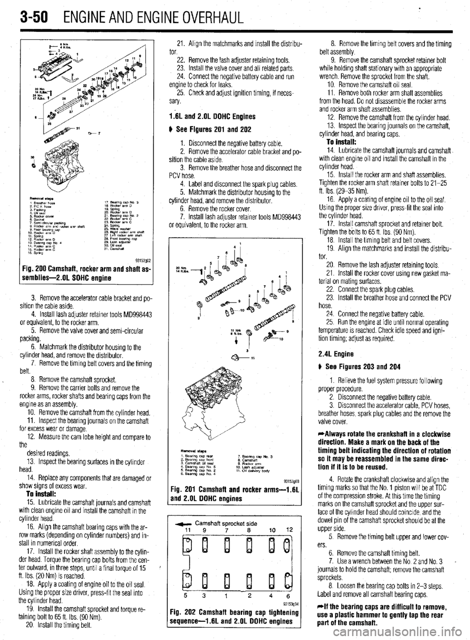
1 s 93153QO2 :ig. 200 Camshaft, rocker arm and shaft as-
iemblies-2.01 SOHC ermine
3. Remove the accelerator cable bracket and po-
sition the cable aside.
4. Install lash adjuster retainer tools MD998443
or equivalent, to the rocker arm.
5. Remove the valve cover and semi-circular
packing.
6. Matchmark the distributor housing to the
cylinder head, and remove the distributor,
7. Remove the timing belt covers and the timing
belt.
8 Remove the camshaft sprocket.
9. Remove the carrier bolts and remove the
rocker arms, rocker shafts and bearing caps from the
engine as an assembly.
10. Remove the camshaft from the cylinder head.
11. Inspect the bearing journals on the camshaft
for excess wear or damage.
12. Measure the cam lobe height and compare to
the
desired readings.
13. Inspect the bearing surfaces in the cylinder
head.
14. Replace any components that are damaged or
show signs of excess wear,
To install:
15. Lubricate the camshaft journals and camshaft
with clean engine oil and install the camshaft in the
cylinder head.
16. Align the camshaft bearing caps with the ar-
row marks (depending on cylinder numbers) and in-
stall in numerical order,
17. Install the rocker shaft assembly to the cylin-
der head. Torque the bearing cap bolts from the cen-
ter outward, in three steps, unh a final torque of 15
ft. Ibs. (20 Nm) is reached.
18. Apply a coating of engine oil to the oil seal.
Using the proper size driver, press-frt the seal into
the cylinder head.
19. install the camshaft sprocket and torque re-
taining bolt to 65 ft. Ibs. (90 Nm).
20. Install the timing belt. 21. Ahgn the matchmarks and install the distrrbu- 8. Remove the timing belt covers and the timing
tor. belt assembly.
22. Remove the lash adjuster retaining tools.
23. Install the valve cover and all related parts
24. Connect the negative battery cable and run
engine to check for leaks,
25. Check and adjust ignition timing, if neces-
sary.
l.‘6L and 2.lJL DOHC Engines
6 See Figures 201 and 202
1. Disconnect the negative battery cable.
2. Remove the accelerator cable bracket and po-
sition the cable aside.
3. Remove the breather hose and disconnect the
PCV hose. 9. Remove the camshaft sprocket retainer bolt
while holding shaft stationary with an appropriate
wrench. Remove the sprocket from the shaft.
10. Remove the camshaft oil seal.
11. Remove both rocker arm shaft assemblies
from the head. Do not drsassemble the rocker arms
and rocker arm shaft assemblies.
12. Remove the camshaft from the cylinder head.
13. inspect the bearing journals on the camshaft,
cylinder head, and bearing caps.
To install:
14. Lubricate the camshaft journals and camshaft
with clean engine oil and install the camshaft in the
cylinder head.
4. Label and disconnect the spark plug cables.
5. Matchmark the distributor housing to the
cylinder head, and remove the distributor.
6. Remove the rocker cover.
7. Install lash adjuster retarner tools MD998443
or equivalent, to the rocker arm. 15. Install the rocker arm and shaft assemblies.
Tighten the rocker arm shaft retainer bolts to 21-25
ft. Ibs. (2935 Nm).
16 Apply a coating of engine oil to the oil seal.
Using the proper size driver, press-fit the seal into
the cylinder head.
17. Instal! camshaft sprocket and retainer bolt.
Tighten the bolts to 65 ft. Ibs. (90 Nm).
18. Install the hming belt and belt covers.
19. Align the matchmarks and install the distribu-
tor.
93153gO: :ig. 201 Camshaft and rocker arms-i.61
rnd 2.OL DOHC engines
r ,
w Camshaft sprocket side
ei i i ij
20. Remove the lash adjuster retaining tools,
21. Install the rocker cover using new gasket ma-
terial on mating surfaces,
22. Connect the spark plug cables.
23. Install the breather hose and connect the PCV
hose.
24. Connect the negative battery cable.
25. Run the engme at idle until normal operating
temperature is reached. Check idle speed and igni-
tion timing; adjust as required.
2.4L Engine
) See Figures 203 and 204
1. Relieve the fuel system pressure following
proper procedure.
2. Disconnect the negative battery cable.
3. Disconnect the accelerator cable, PCV hoses,
breather hoses, spark plug cables and the remove the
valve cover.
*Always rotate the crankshaft in a clockwise
direction. Make a mark on the back of the
timing belt indicating the direction of rotation
so it may be reassembled in the same direc-
tion if it is to be reused.
4. Rotate the crankshaft clockwise and align the
timing marks so that the No. 1 piston will be at TDC
of the compression stroke. At this time the timing
marks on the camshaft sprocket and the upper sur-
face of the cyhnder head should coincide, and the
dowel pin of the camshaft sprocket should be at the
upper side.
5 Remove the timing belt upper and lower cov-
ers.
6. Remove the camshaft timing belt.
7. Use a wrench between the No 2 and No. 3
journals to hold the camshaft; remove the camshaft
sprockets.
8 Loosen the bearing cap bolts in 2-3 steps.
Label and remove all camshaft bearing caps,
*If the bearing caps are difficult to remove,
use a plastic hammer to gently tap the rear
part of the camshaft.
Page 115 of 408
3-54 ENGINEANDENGINEOVERHALJL
from the, access may be possible (though a little
awkward) to measure the camshaft lobes using a mi-
crometer
In any case, two measurements are necessary for
each lobe. Measurement Y or the total LOBE HEIGHT
and measurement X or the total LOBE WIDTH. To
find the lobe lift, you simply subtract X from Y (sub-
tract the width from the height).
Note each measurement, then make your calcula-
tion to determine the lift. Note the final results and re-
peat the process on the remaining camshaft lobes.
Finally, you should compare your results to the spec-
ifications charts and decide if a new camshaft is in
your future.
REMOVAL &INSTALLATION
2.OL and 2.4L Engines
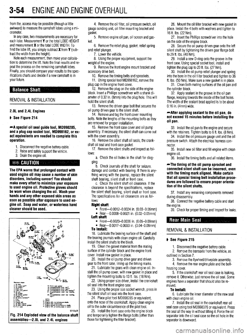
p See Figure 214
*A special oil seal guide tool, 18998285,
and a plug cap socket tool, MD998182, or ex-
act equivalents are needed to complete this
operation.
1. Disconnect the negative battery cable.
2. Raise and safely support the vehicle.
3. Drain the engine oil.
The EPA warns that prolonged contact with
used engine oil may cause a number of skin
disorders, including cancer! You should
make every effort to minimize your exposure
to used engine oil. Protective gloves should
be worn when changing the oil. Wash your
hands and any other exposed skin areas as
soon as possible after exposure to used en-
gine oil. Soap and water, or waterless hand
cleaner should be used.
93153g3
:ig. 214 Exploded view of the balance shaf
assemblies-2.01 and 2.4L enoines
4. Remove the oil filter, oil pressure switch, oil
gauge sending unit, oil filter mounting bracket and
gasket.
5. Remove engine oil pan, oil screen and gas-
ket.
6. Remove the relief plug, gasket, relief spring
and relref plunger.
7. Lower the vehicle.
8. Using the proper equipment, support the
weight of the engine.
9. Remove the front engine mount bracket and
accessory drive belt,
10. Remove the timing belts and sprockets.
11. Using special tool MD998162, remove the
plug cap in the engine front cover.
12. Remove the plug on the side of the engine
block. Insert a Phillips screwdriver with a shank di-
ameter of 0.32 in. (8mm) into the plug hole. This will
hold the silent shaft.
13. Remove the driven gear bolt that secures the
oil pump driven gear to the silent shaft.
14. Remove and tag the front cover mounting
bolts. Note the lengths of the mounting bolts as they
are removed for proper installation.
15. Remove the front case cover and oil pump
assembly. If necessary, the silent shaft can come out
with the cover assembly.
16. Remove the silent shaft oil seals, the crank-
shaft oil seal and front case gasket
17. Remove the silent shafts and inspect as fol-
lows:
a. Check the oil holes in the shaft for clog-
ging.
b. Check journals of the shaft for seizure,
damage and contact with bearing. If there is any-
thing wrong with the journal, replace the silent
shaft bearing, silent shaft or front case.
c. Check the silent shaft oil clearance. If the
clearance is beyond the specifications, replace
the silent shaft bearing, silent shaft or front case.
The specifications for oil clearances are as fol-
lows
Right shaft l Front-0.0012-0.0024 in. (0.030.06mml l Rear+0.0008-0.0021 in. (6.02-O 05mm) Left shaft l Front-0.002&0.0036 in. (0.05-0.09mm) l Rear-O.0017-O.0033 in. (0.04-0.08mm) To install: 18. Lubricate the bearing surface of the shaft and
the bearing journals with clean engine oil. Carefully
install the silent shafts to the block.
19. Clean the gasket material from the mating
surface of the cylinder block and the engine front
cover. Install new gasket in place.
20. Install the oil pump drive gear and driven
gear to the front case, lining up the timing marks.
21. Lubricate the gears with clean engine oil. In-
stall the oil pump cover, with new gasket in place and
tighten the mounting bolts to 13 ft. Ibs. (18 Nm).
22. Using proper size driver, install the crankshaft
oil seal into the front engine case.
23. Using the proper size socket wrench, press in
the silent shaft oil seal into the front case.
24. Place pilot tool MD998285 or equivalent,
onto the nose of the crankshaft. Apply clean engine
oil to the outer circumference of the pilot tool.
25. Install the front case onto the engine block
and temporarily tighten the flange bolts (other than
those for tightening the filter bracket). 26. Mount the oil filter bracket with new gasket in
place. Install the 4 bolts with washers and tighten to
16 ft Ibs. (22 Nm).
27. Insert the Phillips screwdriver into the hole
on the side of the engine block.
28. Secure the oil pump driven gear onto the left
silent shaft by tightening the driven gear flange bolt
to 29 ft. Ibs. (40 Nm).
29. Install a new O-ring onto the groove in the
front case. Using special socket tool, install and
tighten the plug cap to 20 ft. Ibs (27 Nm).
30. Install the oil pump relief plunger and spring
into the bore in the oil filter bracket and tighten to 36
ft. Ibs. (50 Nm). Make sure a new gasket is in place.
31. Clean both mating surfaces of the oil pan and
the cylinder block.
32. Apply sealant in the groove in the oil pan
flange, keeping towards the inside of the bolt holes.
The width of the sealant bead applied is to be about
0.16 in. (4mm) wide.
*After applying sealant to the oil pan, do
not exceed 15 minutes before installing the
oil pan.
33. Install the oil pan to the engine and secure
with the retainers. Tighten bolts to 6 ft. Ibs. (8 Nm).
34. Install the oil pressure gauge unit and the oil
pressure switch. Attach the electrical harness con-
nector
35. Install new oil filter and fill engine with clean
engine oil.
36. Install the timing belts and all related items,
*The timing of the oil pump sprocket and
connected silent shaft can be incorrect, even
with the timing mark aligned. Make certain
that all special timing belt installation proce-
dures are followed to ensure proper orienta-
tion of the silent shafts.
37. Install any remaining components removed
during disassembly.
38. Connect the negative battery cable and start
the engine.
39. Check for proper timing and inspect for leaks.
REMOVAL &INSTALLATION
p See Figure 215
1. Disconnect the negative battery cable.
2. Remove the transaxle from the vehicle, as
outlined in Section 7.
3. Remove the flywheel/driveplate assembly.
4. Remove the rear engine plate and the bell-
housing cover.
5. If the crankshaft rear oil seal case is leaking,
remove it. Otherwise, just remove the oil seal. Some
engines have a separator that should also be re-
moved.
To install: 6. Lubricate the inner diameter of the new seal
with clean engine oil.
7. Install the oil seal in the crankshaft rear oil
seal case using tool MD998376 or equivalent. Press
the seal all the way in without tilting it. Force the oil
separator into the oil seal case so the oil hole in the
separator is downward.
Page 123 of 408
.
3-62 ENGINEANDENGINEOVERHAUL
lge. To accurately inspect them, you will need some
,pecialized tools:
l A O-l in. micrometer for the valves l A dial indicator or inside diameter gauge for
he valve guides
l A spring ressure test gau e
If you do no P Yl have access to t e proper tools,
‘ou may want to bring the components to a shop
hat does.
lalves
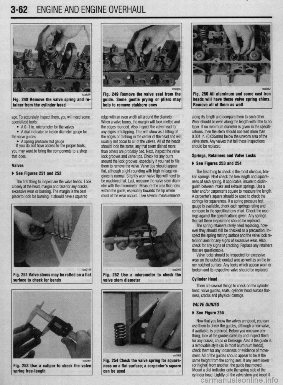
1 See Figures 251 and 252
The first thing to inspect are the valve heads. Look
E :losely at the head, margin and face for any cracks,
rxcessive wear or burning. The margin is the best
)lace?o look for burning. It should have a squared E
c
edge with an even width all around the diameter.
When a valve burns, the margin will look melted and
the edges rounded. Also inspect the valve head for
any signs of tulipping. This will show as a lifting of
the edges or dishing in the center of the head and will
usually not occur to all of the valves. All of the heads
should look the same, any that seem dished more
than others are probably bad. Next, inspect the valve
lock grooves and valve tips. Check for any burrs
around the lock grooves, especially if you had to file
them to remove the valve. Valve tips should appear
flat, although slight rounding with high mileage en-
gines is normal. Slightly worn valve tips will need to
be machined flat. last, measure the valve stem diam-
eter with the micrometer. Measure the area that rides
within the guide, especially towards the tip where
most of the wear occurs. Take several measurements along its length and compare them to each other.
Wear should be even along the length with little to no
taper. If no minimum diameter is given in the specifi-
cations, then the stem should not read more than
0.001 in. (0.025mm) below the unworn area of the
valve stem. Any valves that fail these inspections
should be replaced.
Springs, Retainers and Valve Locks
$ See Figures 253 and 254
The first thing to check is the most obvious, bro-
ken springs. Next check the free length and square-
ness of each spring. If applicable, insure to distin-
guish between intake and exhaust springs. Use a
ruler and/or carpenter’s square to measure the length.
A carpenter’s square should be used to check the
lCZS3144
I I hrnknn itc Fig. 251 Valve stems may be rolled on a flat Fio. 252 Use a micrometer
suhace to check for bends
valve stem diameter r to check the
I
There are seve Cylinder Head
ral things to check on the cylinder
head: valve guides, seats, cylinder head surface flat-
ness, cracks and physical damage.
VA1 YE GUIDES
N See Figure 255
Now that you know the valves are good, you can
254 Check the valve spring fo
s on a flat surface; a carpenter use them to check the guides, although a new valve,
if available, is preferred. Before you measure any-
thing, look at the guides carefully and inspect them
for any cracks, chips or breakage. Also if the guide is
a removable style (as in most aluminum heads),
check them for any looseness or evidence of move-
ment. All of the guides should appear to be at the
same height from the spring seat. If any seem lower
(or higher) from another, the guide has moved.
Mount a dial indicator onto the sorina side of the
cylinder head. Lightly oil the valve stem and insert it
Page 131 of 408
1.5L ENGINE MECHANICAL SPECIFICATIONS English
Metric
Description
Specificationr
Specifications
General Information
Engine type
4 Cylinder In-Line Ovethead Camshaft
Displacement 69 6 cubic I” 15L
sore 2 972 I” 75 5mm
Stroke 3 226 I” 82mm
Compression rat10 921
Firing order
l-3-4-2
Cylinder Head
Overall height 4 209.4 217 I” 1059-107 lmm
Flatness (maximum) 0 002 I” 0 05mm
Camshaft bearing-to-camshaft clearance 0 0016-O 0031 I” 0 04-O OBmm
Camshaft
Camshaft height
Intake
Standard 1 5256 I”. 39 75mm
Limit
1.5059 In 38.25mm
Exhaust
Standard 1 5394 I” 391mm
Llmlt 1 5197 In 38 6mm
Journal outside diameter -
161101”
46mm
Bearing 011 clearance
Standard
0 1X324.0 a)39 I” 0 06-O 10mm
Rocker arms Limit
0 0055 I” 0 14mm
lwde diameter
Arm-to-shalt clearance
Standard 0 744 I”. 18 Smm
0 OCQ4-0 0016 I”. 0 Old 04mm
Llmlt 0 004 I” Olmm
Rocker arm shaft
OutsIde diameter 0 744 I” 16 9mm
Valves
Valve length
Intake 3 9665 I” 100 75mm
Exhaust 3 9763 I” 101.05mm
_ Stem outslde diameter
Intake 0 2585.0 2591 I” 6.565-6 5tlOmm
Exhaust 0 2571-o 2579 I” 6 530-6 55Omm
Face angle (ail)
45-45 5”
Head thickness (margm)
Intake
Standard 0 039 I”. 1 Omm
Llmlt
0 02u In. 05mm
Exhaust
0 059 I”
0 039 I”. 1.5mm
1 .Omm
0 02-O 05mm
0 1Omm
0 05-O OSmm
0 15mm
0 15mm
0 25mm
0 07mm Cescriptlon
Valve guide 1.5L ENGINE MECHANICAL SPECIFICATIONS English
Specifications Metric
Specifications
Length
Intake 1 732 I” 44 Omm
Exhaust
Selwe wes
Valve seat
Seat contact width
Seat angle (all)
Valve spring
Free length
Intake
Standard
Llmlt
Exhaust
Standard
Llmlt 1 949 I” 49 5mm
0002,0010.002cIn 0 05,O 25,O 50mm
0 035-o 051 I” 0 S-1 3mm
44.44 5”
1 615 I” 461mm
1 776 I” 451mm
1 643 I” 46 8mm
1 603 I” 45 6mm
Load
Intake
Exhaust 64 It Ibs. 290Nm
Cylinder Block
Bore
Dnmeter
Out-of-round (ma)
Taper (max.) 2 9724-Z 9736 I” 75 50.75 53mm
0 006 I” 0 02mm
0 006 I” 0 02mm
Overall height
Standard
Llrnbt 10075-10083In 255 9.256 1 mm
10 073 I” 254 62mm
No 1
Standard 0 0012-o 0028 I”. 0 03-O 07mm
Llmlt 0 0047 I” 0 12mm
No 2
Standard 0 OCOE-0 0024 I” 0 02-O 06mm
Llmlt 0 0047 I” 0 l2mm
End gap
No 1
Standard
Limit
No 2
Standard
Ltmlt
01
Standard 0 0079-o 0157 I”.
0 I” 031
0 0079.0.0136 I”
0.031 I”
0 0079.0 0276 I” 0 20-O 40mm
0 8mm
0 20-O 35mm
0.8mm
0 20-O 70mm
Limit
Connecting rod
Bend (mex)
Twst (max) 0 039 I” 1 Omm
0 CO20 I” 0 05mm
0 0039 In 0 10mm
Page 132 of 408
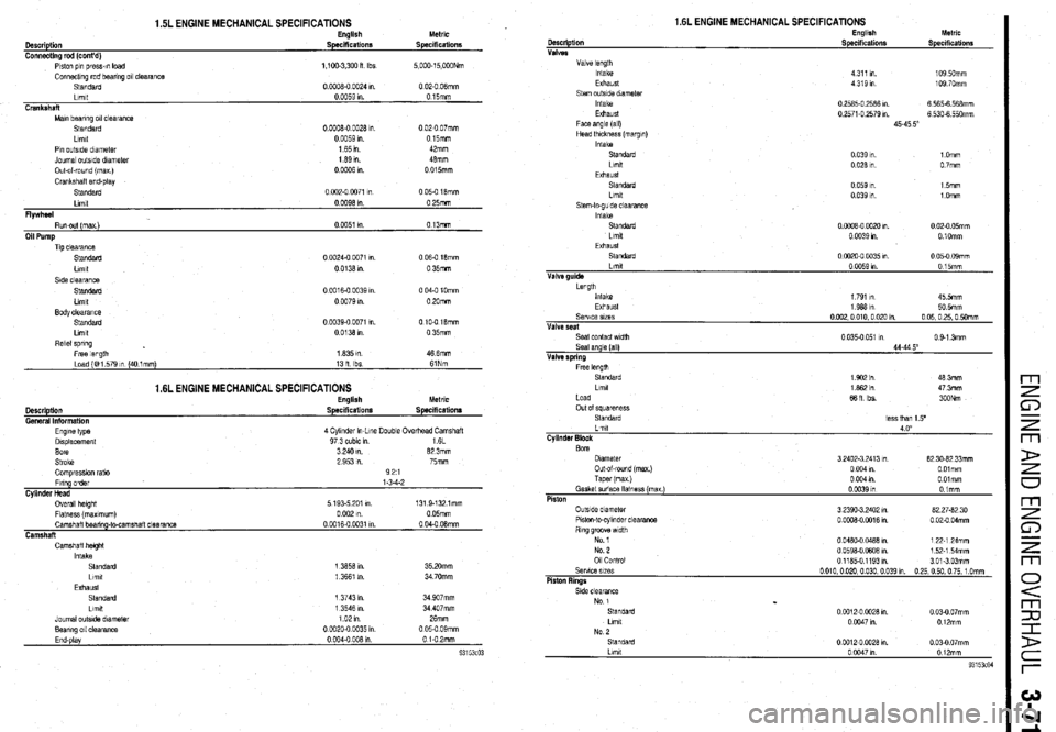
1.5L ENGINE MECHANICAL SPECIFICATIONS English
Description Specifications
Connecting rod (cont’d)
Piston p,n press-m load
1,100.3,300 II Ibs
Connecting rod bearing 011 clearance
Standard 0 0006-O CO24 I”
Limit
0 0059 I”.
Crankshaft
Main bearing 011 clearanc8
Standard
0 0006.0 0026 I”
Ltmit
0 0059 I”
Pin outslde diameter 165111
Journal outside dlametei
1 89 I”.
Out-al-round imax I 0oLx%l” Metric
Specifications
5,000.15,OWNm
0 02-O 06mm
015mm
0 02-O 07mm
0 15mm
42mm
46mm
0 015mm
SI& clearance
Standard
0 0016-O 0039 I” 0 04-O 1Omm
Llmtt
0 0079 I” 0 20mm
Body clearance
Standard
0 0039-o 0071 I”. 0 10-O 16mm
Llmlt 0013am 0 35mm
AelM
spring . Free length
1635 I” 46 6mm
Load (@ 1 579 tn (40 1 mm)
13H Ibs 61Nm
Description
General Information
1.6L ENGINE MECHANICAL SPECIFICATIONS English
Specifications Metric
Specifications
Camshaft height
Intake
Standard
Llmlt
Exhaust
Standard
Llmlt 1 3556 I” 35 2Omm
1 3661 I” 34 70mm
1 3743 I” 34 W7mm
1 3546 I”. 34 407mm
Journal outslde diameter 1021n 26mm
Bearing 011 clearance
0 0020-0 w35 I” 0 05-0 09mm
End-play
0 004.0 oQ6 In 0 i-02mm
1.6L ENGINE MECHANICAL SPECIFICATIONS
Page 135 of 408
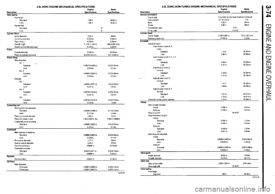
2.OL SOHC ENGINE MECHANICAL SPECIFICATIONS
Description
General Information
2.OL DOHC (NON-TURBO) ENGINE MECHANICAL SPECIFICATIONS English
Specifications Metric
Speciticatlonr Description
Valve sorino Engbsh
Specifications Metric
Specifications
Engine type
Dlsplacemenl
Bore
Stroke
Comprwon rat10
Flung order
Cylinder Head
Overall height
Flatness (maximum)
Camshaft 4 Cylmdet In-Lone Dual Overixad Camshaft
12’ 3 cubic m 2OL
3351n 85mm
3 46 I” 68mm
981
l-54-2
5 193.5 201 Ill 131 9.1321mm
0 008 1” 0 2mm S&dard
Llmlt
Squareness
Standard
Gasket surface flatness (mex Llmll
) Cylinder Block
Piston lnslde diameter
Outside dlameler O&of-round (max)
Piston-lo-cylinder clearance Taper (max)
Piston Rings Overall height 1 36 I”
1 96 I”
2”
0 002 I”. 4”
0 05mm 335m
3 346 I”. 65mm
64 99mm 0 008
0 I”.
004-o 04312 0 02mm
I” 0 008
0 I”
01-O 03mm 0 02mm
11 413.11 421 I” 263 Q-290 lmm m
Camshaft height
lndentlficaiw mark A, D
Intake
Standard
Llmlt
lndentll!cat!on mark B C, E, F
Intake
Standard
Llmlt
lndentlllcallon mark A
Exhaust
Standard
Lrmt
lndenbllcabon mah C
Exhaust
Standard
Limit 35 49mm
34 99mm 14m
1 36 I”.
0.0012-0 0026 I”.
0 004 I” 0 03-O 07mm
01mm 35 20mm
34 70mm 1 39 I”.
1 37 I”.
7 m 1 39 I”.
1 37 I”. 35 20mm
34 70mm 0 0008-O 0024 I”
0 004 I” 0 02-O 06mm
Olmm
14m
1 38 I”. 35 49mm
34 QQmm 0 0098-0 0157 I”.
0 031 I” 0 25.0 40mm
0 6mm
0.0079-O 0136 I”.
0 031 I” 0 20-O 35mm
08mm
0 0079-O 0276 I”.
Stem outside diameter
Intake
Exhaust
Face angle (all)
Head lhlckness (margm)
Intake
Standard
Llmlt 0 260 I”. 6 6mm
0 256 I”. 6 5mm
45-45 50
0 039 WI. 1 Omm
0 020 I”. 0 5mm Piston pm outside diameter
Piston p,” press-!” load
Crankshaft PI” 011 clearance
Standard 0631ll
1,653.3,656 ft Ibs 21mm
7,500.17,5WNm
0 oooa-o 0020 In. 0 02-O 05mm
Exhaust
Standard
Limit 0 059 I”.
0 031 I”. 15mm
0 6mm Limit
0 004 I” Olmm
Crankshaft
Man bearing 011 clearance
Standard
Llmlt
Pm outside dwneler
Journal outslde diameter
Out-of-round (max)
CrankshaH end-play
Standard
Limtt
Flywheel
Run-out (max)
Oil Pump 0 ciw0 0020 I”. 0 02-O 05mm
0 004 I”. Olmm
1771n 45mm
2 24 I” 57mm
0 0006 I” 0 015mm
0 002-O 0071 I” 0 05-O 16mm
0 0098 I” 0 25mm
0 0051 I” 0.13mm Stem-to-gude clearance
Intake
Standard
Llmlt 0 oooa-o 0020 I” 0 02-O 05mm
0 0039 in 0 1Omm
Exhaust
Standard 0 0020-O 0035 I” 0 05-O 09mm
Llmlt
Valve guide
lnstde diameter
OutsIde diameter
Valve seat
Seal contact wldlh
Seat angle (all)
Valve spring 0 W59 m 0 15mm
026Om 66mm
0 476 I” 121mm
0 035-o 051 I”. 0 Q-1 3mm
44-44.5
Page 136 of 408
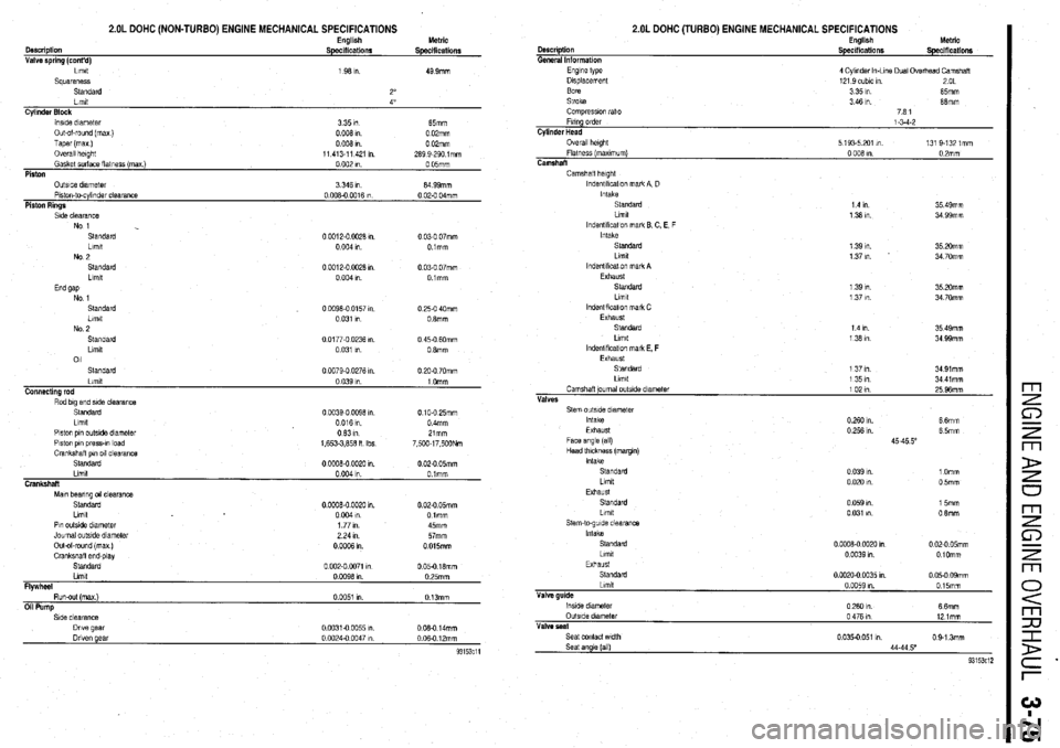
2.OL DOHC (NON-TURBO) ENGINE MECHANICAL SPECIFICATIONS
Cyltnder Block
lnslde dnnetet
335m 65mm
Out&round (ma)
0 006 I” 0 02mm
Taper (ma)
oooh
0 OPmm
Overall haght
11 413-l 1 421 I”. 269 9-290 lmm
Gasket surface flatness (ma )
0 002 I” 0 05mm
Piston
Side clearance
No 1
Standard
Llmlt
No 2
Standard
Llmlt 0 0012-O 0028 I”. 0 03-O 07mm
0 004 I” Olmm
0 0012-O W26 I”
0 03-O 07mm
0 004 I” Olmm
Standard
00096-0 0157 I” 0 25-O 40mm
Limit
0 031 I” 0 8mm
No 2
Standard
0 0177-O 0236 I” 0 45-O 6Omm
Llmlt 0 031 I”. 0 6mm
011
Standard
0 0079.0 0276 I” 0 20-O 70mm
Piston pin outslde diameter
Ot331n
Piston own oress-m load
1.653-3.856 n Ibs Zlmm
7 500-l 7 500Nm
Mm bearing 011 clearance
Standard
Llmlt
Pin outsIde diameter
Journal outslde diameter
Out-of-round (max )
Crankshall end&v 0 OOOB-0 0020 1” 0 02-O 05mm
0 004 I” Olmm
1 77 I”. 45mm
2 24 I”. 57mm
0 0006 I” 0 015mm
Standard’ ‘
0 002-O 0071 I” 0 05-O 16mm
Llmlt
0 0096 I”. 0 25mm
FlVWheel
Run-out (max)
0 BO51 I” 0 13mm
Oil Pump Description
General Information
2.OL DOHC (TURBO) ENGINE MECHANICAL SPECIFICATIONS English
Specifications Metric
Specifications
Camshafl height
lndentlkcatlon mark A. D
Intake
Standard
1 4 In 35 49mm
Llmlt
1 36 I” 34 99mm
lndentlflcatlon mark E C. E, F
Intake
Standard 1 39 I”. 35 20mm
Llmlt 1 37 I”. 34 70mm
lndentlflcal!on mark A
Exhaust
Standard
1 39 I”. 35 20mm
Llmlt
1 37 I”. 34 70mm
lndentlflcatlon mark C
Exhaust
Standard
1 4 I” 35 49mm
Llmlt
1 36 I” 34 99mm
lndentlflcatlon mark E, F
Exhaust
Standard
1 37 I”. 34 91mm
Llmlt
1351n 34 41 mm
Camshaft journal outslde dlametar
1021n
25 96mm
Vhf&S
Standard
LilTlIt
Exhaust 0 039 I”. 1 Omm
0 020 I”. 0 5mm
Standard
Llmlt
Stem-to-guide clearance
Intake
Standard
Llmtt
Exhaust
Standatd
Limit
Valve guide
lnslde diameter
OutsIde dlametat
Valve peat
Seat contact wdth
Seat angle (all) 0 059 I”. 15mm
0 031 I”. 0 6mm
0 0008-0 0020 I” 0 02-O 05mm
0 0039 I” OlOmm
0 0020-0 0035 I”. 0 05.0 09mm
0 0059 I”. 015mm
0260 In.
66mm
0 476 I” 12 lmm
0 035-o 051 m 0 9.1 3mm
44.44 5”
93153c12
Page 137 of 408
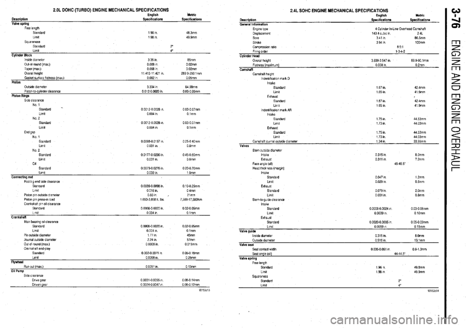
Description
Valve spring
Free length
Standard
Llmlt
Squareness
Standard
Llmlt
2.OL DOHC (TURBO) ENGINE MECHANICAL SPECIFICATIONS English Metric
Specifications Specifications
1 90 I”. 46 3mm
1 98 I” 49 9mm
2’
4’ 2.4L SOHC ENGINE MECHANICAL SPECIFICATIONS
Description
General Information
Engine type
Displacement
Bore
Stroke
Compression rat10
Frrlng order
Cylinder Head
Overall height
Flatness (maxlmum)
Camshaft
Camshaft height
lndenbflcatlon mark D
Intake
Standard
Llrnd
Exhaust
Standard
Limit
lndenbflcabon mark AR
Intake
Standard
Llmlt
Exhaust
Standard
Llmlt
Camshalt journal outside dnmeter
Valves
Stem outside diameter
Intake
Exhaust
Face angle (all)
Head thickness (margm)
intake
Standard
Llmlt
Exhaust
Standard
Llmlt
Stem-to-guide clearance
Intake
Standard
Llmlt
Exhaust
Standard
Llmlt
Valve guide
lwde diameter
OutsIde diameter
Valve seal
Seat contact wdlh
Seat angle (all)
Valve spring
Free length
Standard
Llmlt
Squareness
Standard
Llmlt English MlxdC
Specifications Specifications
4 Cylinder In-Lme Overhead Camshaft
143 4 cLblc I” 24L
341 I” 86 5mm
3941n 1OOmm
651
l-3-4-2
3 539-3 547 I” 89 9-90 1 mm
0 008 1” 02mm
167Ill 42 4mm
165vl 419mm
167m 42 4mm
165In 419mm
1751n 44 53mm
1.73 I” 44 03mm
175m 44 53mm
I 73 I” 44 03mm
1 34 I” 33 95mm
0315m 8 Omm
0311 I” 7 9mm
45.45 5
0047m 1 2mm
0.020 I” 0 5mm
0 079 I” 2 Omm
0 031 ,” 0 8mm
0 0008-O 0024 I” 0 03-O &mm
0 0039 I” 0 1Omm
0 oQ20-0 0035 I” 0 05-O 09mm
0 0059 In 0 15mm
0 315 tn. 8 Omm
0 516 I” 131mm
0 035.0 051 I” 0 9-l 3mm
44-44 5”
1961n 49 6mm
I 98 I” 49 9mm
2”
4”
93153ci4