1900 MITSUBISHI DIAMANTE height
[x] Cancel search: heightPage 138 of 408
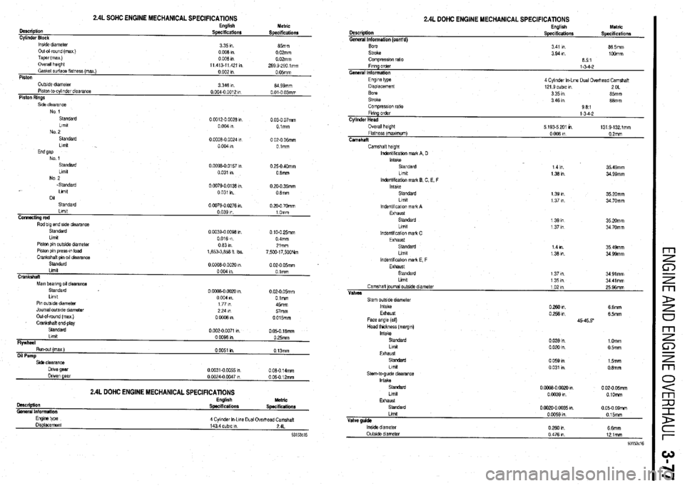
2.4L SOHC ENGINE MECHANICAL SPECIFICATIONS English
Description
Specifications
Cylinder Block
lnstde dnmeter
3 35 I”.
Out-o-round (max )
0008ln
Taper(max)
0008ln
Overall hwght
11 413-11 421 I”
Gasket &ace flatness (max )
0 002 I”
Piston Metric
Specifications
85mm
0 02mm
0 02mm
289 9-290 lmm
0 05mm
OutsIde dlameler
Plslon-to-cylinder clearance
Piston Rings 3 346 I” 04 99mm
0 004-o 0012 I” 0 01-O 03mm
Standard
0 0012-O 0928 I” 0 03-O 07mm
Lfmlt
0 004 I” Olmm
No 2
Standard 00008-O
0024 I” 0 02-O ffimm
Llmlt
0004," Olmm
End gap
No 1
Standard 0
0098-O 0157 In 0 25-O 40mm
Llmlt
0 031 I”. 0 Smm
No 2
.Standard
Llmlt
011
Standard 0 0079-o 0138 I”
0 031 I”.
00079-002761". 0 20-O 35mm
0 8mm
0 20-O 70mm
Standard
Llmlt
Piston pin outside dlametar
Piston pin press-m load
Crankshaft om 011 clearance 0 0039-o 0098 I” 0 10.0 25mm
0 016 m 0 4mm
0631n 21mm
1,653-3,&a fl Ibs.
7,500~17,500Nm
Standard
0 02-O 05mm
Mam beanna 011 clearance
Standard
0 OuoE-0 0020 I”. 0.024 05mm
Limit
0004 I”. 0 lmm
Pm outslde diameter
1 77 I” 45mm
Journal outside diameter 2P4m wmm
Out-al-round (max )
Crankshaft end-play
o-i& I”. _
0015mm
Flywheel Standard
Ltmit 0002-00071 I”.
0 050 18mm
000981n 0 25mm
Side clearance
Dnve gear
Driven gear
lMCriptlOfl
General Information OOm-00055,"
0 0024-O 0047 I”
2.4L DOHC ENGINE MECHANICAL SPECIFICATIONS English
Specifications 0 08.0 14mm
006012mm
Metric
Specifications
4 Cyi~nder In-Lme Dual Overhead Camshaft
143 4 cubtc I”. 24L
2.4L DOHC ENGINE MECHANICAL SPEClFlCATlONS
Description
General Information (cont’d) English
Specifications Metric
Specifications
Fmng order
Cylinder Head
Overall height
Flatness (maxtmum)
Camshaft l-3-4-2
5 193.5 201 K1 131 9-132 lmm
0 008 I” 0.2mm
Camshaft height
lndentlhcabon malk A, D
Intake
Standard
Limit
lndentlkcatlon mark 8, C, E. F 1 4 I”. 35 49mm
1331n 34 99mm
Head thickness (margtn)
Intake
StaMkrd
hrnft
Exhaust
Standard
Llmlt
Stem-to-gulda clearance
Intake
Standard
Llmlt
Exhaust
Standard
Limit
Valve guide
lnslde diameter
Outside diameter 0 039 I”. 1 Omm
0 020 I”. 05mm
0 059 I” 15mm
0 031 I” 0.8mm
0 cooa- NJ20 I”. 0 02-O 05mm
0 0039 I”. O.lOmm
0002+0M)35m 005.009mm
0 0059 I”. 015mm
02mm 6 6mm
0 476 I”. 121mm
Page 139 of 408
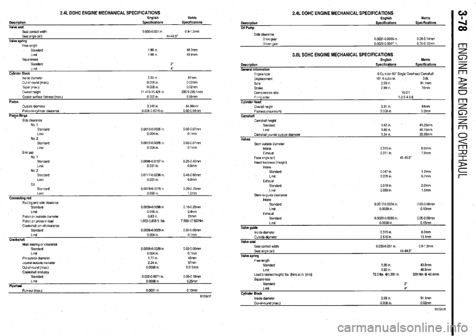
2.4L DOHC ENGINE MECHANICAL SPECIFICATIONS English Metric
Description Specifications Specdications
Valve seat
Seat contact wldlh 0.035-o 051 I”
0 9-l 3mm
Seat angle (all) 44-44 5”
Valve spring
Free length
Standard 1901n 46 3mm
Llmlt
1 96 I” 49 9mm
squareness
Standard 2”
Llmlt 4”
Cylinder Block
lwde diameter 3351n 65mm
Out-of-round (max)
0 006 in 0 02mm
Taper (mu)
0 006 I” 0 02mm
Overall height
11 413-11421 I” 269 9-290 lmm
Gasket surface llatnass (max )
0 002 In 0 05mm
Piston
OutsIde diameter
3 346 In 64 99mm
Plslon-lo-cylinder clearance
0 006.0 0016 m 0 02.0 04mm
PioFn Rings
Side clearance
No 1
Standard
0 0012-O 0026 I”
0 03-O 07mm
Limit
0 004 I”. Olmm
No 2
Standard
0 Cot 2-o 0028 I”
0 03-O 07mm
Llmlt
0 004 I” Olmm
End 9ap
No 1
Standard O.W96-0 0157 I”
0.25-O 40mm
Llmtt
0 031 I”. 0 6mm
NO 9
.__
Standard
Lrmt
011 0 0177-O 0236 I”
0 031 I” 0.45-O 6Omm
0 6mm
Standard
Llmll
Connecting rod
Rod big end side clearance
Standard
Llmlt
Plston pin outsIde dlametar
Piston p,” press-,” load
Crankshatl pin 011 clearance
Standard
Llmlt
Crankshaft
Man bearing 011 clearance
Standard
Llmlt 0
0979.0 0276 I”
0 039 I”
0 0039-o co96 I”
0 016 m.
0631n
1,653.3,656 H Ibs
0
0006-0 0020 I”
0004m
0
0006-0 0020 1”
0 004 I” 0 PO-O 70mm
1 Omm
0 10-O 25mm
0 4mm
Zlmm
7,5Wl7,500Nm
0 02-O 05mm
0 tmm
0 02-O 05mm
Olmm
Pin outstde dlameler
Journal outside diameter
Out-of-round (max )
Crankshalt and-play
Standard
Llmll
Flwhd 177m 45mm
224111 57mm
ooGQ6m 0015mm
0 002-o 0071 I”. 0 05-O 16mm
OW96Ul 0 25mm
I -. Run-out (max)
0 0051 I” 0 13mm
93153ci7
2.4L DOHC ENGINE MECHANICAL SPECIFICATIONS
0 06-O 14mm
3.OL SOHC ENGINE MECHANICAL SPECIFICATIONS
Description
General Information
Engme type
Displacement
Bore
Stroke English
Specifications Metric
Specifications
6 Cylmder GO” Single Overhead Camshatl
161 4 cubic I” 3OL
3 59 I”. 91 lmm
2 99 In. 76mm
Compreswn rat0
Firing order
Cylinder Head
Overall helghl
Flatness (maxImum)
Camshaft 1001
1-2-3-4-5-6
3 31 I” 64mrn
0 006 I” 0 2mm
Camshaft helgM
Standard
1 62 ,n 41 25mm
Llmlt
1601n 40 75mm
Camshaft ~oumal outslde diameter
1 34 I” 33 95mm
Valves
Seat contact width 0 9-1 3mm
Seat angle [all)
Valve spring
Free length
Standard
1.96 I”. 49 0mm
Llmlt
Load (Installed height) Ibs (Nm) at m (mm)
72.5 Ibs @l 591 I”.
Squareness
Standard 46 6mm
329 Nm @! 40.4mm
Lmxt 4’
Cylinder Block m
Page 140 of 408
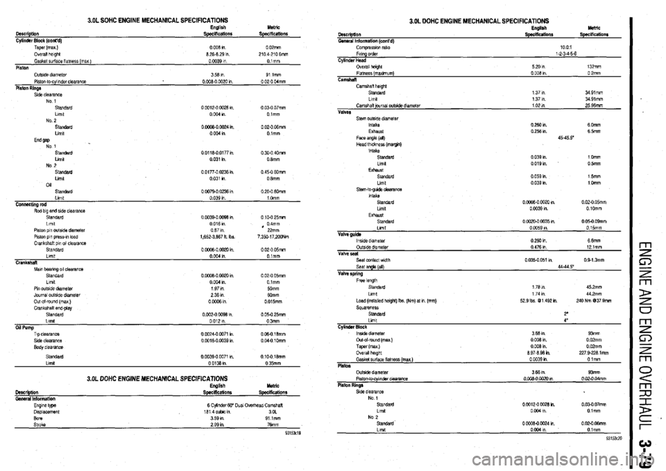
Description
Cylinder Block (cont’d)
3.OL SOHC ENGINE MECHANICAL SPEClFlCATlONS English
Specifications Metric
Specifications
Taper (max.)
Overall klght
Gasket sudace flatness (max )
Piston
Oufslde diameter
Piston-to-cylinder clearanca
Piston Rinas 0008ln 0 OZmm
8 28.8 29 I”. 2104-210 6mm
0 ofI39 In Olmm
358ln. 91 lmm
0.008-o 0020 I” 0 020 04mm
.,
Side clearance
Standard
Llrw
No 2 0 COIZ-0 W28 I”. 0 03-O 07mm
0004 I” Olmm
Standard
0 0008-0 0024 I”. 0 020 06mm
Ltmlt
00041” Olmm
End gap
No 1
Standard 00118-00177,”
0.30-O 40mm
Llmlt
0 031 I” 0 8mm
No 2
Standard
0 0177-O 0236 I”. 0 45-O 60mm
Llmlt
0.031 I” 0 8mm
011
Standard
0 0079-o 02% I” 0 200 fiOmm
Llmlt
0 039 I” 1 Omm
C0nnactlng rod
Rod big end side clearance
Standard
Llmlt
Piston pin outslde diameter
Piston pin prawn load
Crankshaft pm 011 clearance
Standard
Llmlt
Crankshat
Mm bearing 011 clearance
Standard
Llmlt 0 00390 0098 I”.
0 016 m
087al
1,652.3.867 It Ibs.
0 ow3-0 mm I”.
0004m
o.rYm-0 oao I”.
0 Oil4 1” 0 10.0 25mm
, 04mm
22mm
7.350.17,ZOONm
0 02-O 05mm
O.lmm
0 02.0 05mm
Olmm
Pm outs& dfameter
Journal outs& diameter
Out-al-round hnax 1 197n
50mm
236111
0 OW8 in
FT~p clearance
St& clearance 0 0024.0 0071 I”. OC6016mm
0 0016-O 0039 I”. 004-O 10mm
Body clearance
Standard
Llmlt o.cn340 0071 I”.
0 0138 I”
3.OL DOHC ENGINE MECHANICAL SPECIFICATIONS English 010-018mm
0 35mm
M&lC
Description
Spscificalions SpecHicatiOllS Gemal lrlformtlon
Eqne type
Displacement
Bore
Slfoke 6 CylmderW Dual Overhead Camshaft
1814cubicm. 3OL
359m 91 lmm
2 99 I”. 76mm
9315x19
3.OL DOHC ENGINE MECHANICAL SPECIFICATIONS English Metric
Dsscription
General lnformstlon (cont’d) Specifications
Compraswm ratio
Fmng order
l-2-3-45-6
Cylinder Head
Overall helghl
5 20 I”. 132mm
Flatness (manmum)
0 008 I” 0 2mm
Camshall
Camhalt height
Standard
1 37 m 3491mm
Llmll
1 37 I”. 3491mm
Camshalt journal out&e
diameter 1 02 m. 25 96mm
VdVRS
Stem outsrde diameter
Intake
0 260 I”. 60mm
Exhaust
0 256 I”. 6 5mm
Face angle (all) 45-45 5”
Head thickness (mamn)
Intake
Standard
0 039 I” 1 Omm
Llmlt
0019,” 0 5mm
Exhaust
Standard
0 059 I”. 15mm
Llmlt
0 039 m. l.Omm
Stem-to-gude clearam
intake
Standard
0 oo#l-0 002il I”. 0 02-O 05mm
Limit
0 0039 I”. 0 IOmm
Exhaust
Standard
0 0020-0 0035 I”. 0 05-O 09mm
Lllllll
0 0059 m. 0 15mm
Valve guida
lwde dtameter
0 280 In. 6 6mm
Outs& diameter
0.476 I” 12 lmm
Vahre seal
Seat contact wtdlh
0 035-o 051 ,“. 0413mm
Seat angle (all)
44.44 5’
Valve spring
Llmlt
4”
Cvlindsf Block
tnslde dlametar
Out-&round (max )
Taper (max)
Overall hslght
Gasket surface llatnezs (max.)
Platen
Outs& diameter
Plslon-t@cylmn&r Clearance
Piston Rings 3.66 I”. 93mm
0 008 I”. 0 02mm
0 006 I”. 0 OPmm
8 97-8 98 in. 227 9.228 1 mm
0 CO39 I” Olmm
3 66 I”. 93mm
o.oQB-0 0020 M. 0 020.04mm
Page 141 of 408
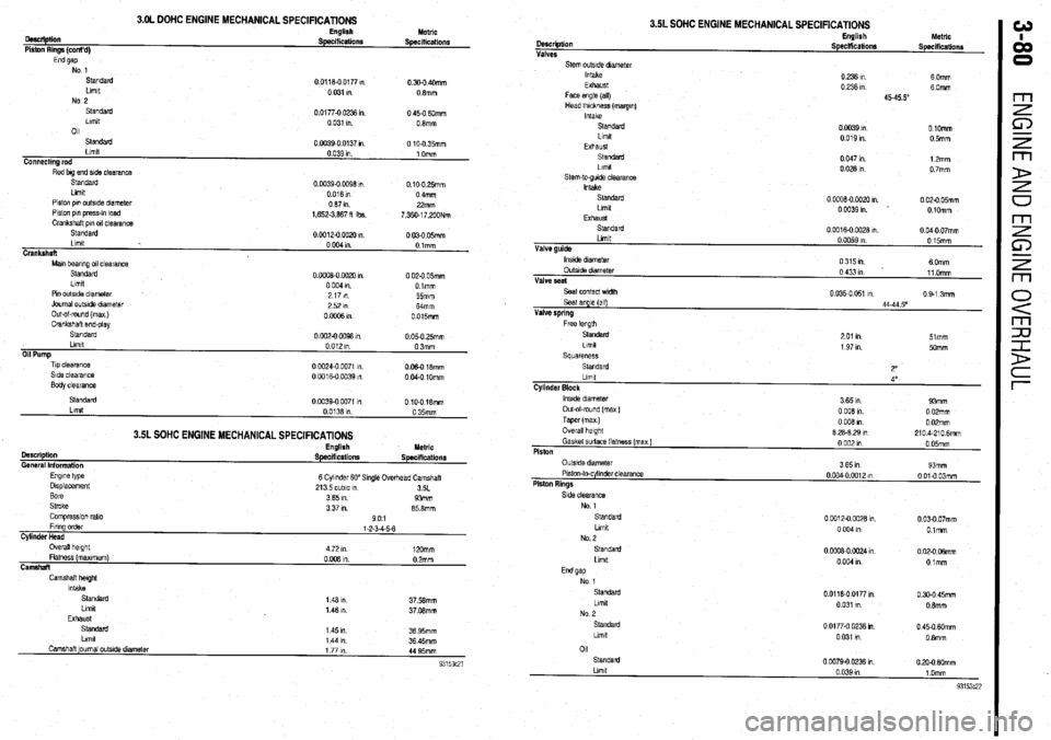
3.OL DOHC ENGINE MECHANICAL SPECIFICATIONS
oescliptiin
Piston Rings (cont’d) English Metric SpeclfiCatiOllS Specifications
End gap No 1
standard
Llmlt
No 2
Standard
Llmlt
011 0 0118-O 0177 ,“.
0.300 40mm
0 031 I” 08mm
0.01770 0236 I” 0 450 6Omm
0 031 I”. 08mm
Standard
Llmlt
Connecting rod
Rod big end side clearance 0.0039-0 0137 I” 0 10-O 35mm
0.039 1” 1 Omm
Slandard
Llmlt
Piston pm outside dnmeter
Piston pi” press-,” load
Crankshaft pm 011 clearance 0.0039-O 0098 m. 0.100 25mm
0016m 0 4mm
087111 22mm
1,652.3,887 fl Ibs.
7,350.17,200Nm
Standard
00012-oOOx)m
0 030 05mm
Llmlt
0 004 I” Olmm
Crankshaft
Mm bearing 011 clearanca
Standard
Llmlt 0 ooO8-0 0020 I” 0 020 05mm
0 004 9”. Dimm
Pm outslde diameter
Journal outs& dlametar
Out-ol-round (max )
Crankshaft end-play
standard
Llmlt
Oil Pump
Tip clearance
Side clearance
Body clearance 2171n
55mm
2521n
Mmm
OoOffiRl 0 015mm
0 002-O 0098 I” 0 05-O 25mm
0 012 I” 03mm
0 CO24.0 0071 m
006018mm
0 0016-O 0039 in. 0 040 1Omm
3.5L SOHC ENGINE MECHANICAL SPECIFICATIONS
Description
General Information
Engme type
Displacement
Bore
Stroke
Comprasslon ratio English Metric
Specifications Specifications
6 Cylinder 60” Single Ovedvzad Camshaft
213 5 cubic I”
3SL
3 65 I”. 93mm
3 37 m. 85 8mm
901
Llmlt
Camshaft ]oumal outs& dtameter 1 44 I”. 36 45mm
1771n
44 95mm
3.5L SOHC ENGINE MECHANICAL SPECIFICATIONS
Llmlt Description
Valve guide Valves
Stem outstde dmmetar
Intake
Exhaust
Face angle (all)
Head thickness (margm)
Intake
Standard
Llmlt
Exhaust
Sl.SldZld
Llmd
stem-to-gude clearance
Intake
standard
Llmlt
EXhaUsl
standarc
0 0059 I” English
0 15mm hletrlc
Speciffcationr
Specificationr
0 236 I”. 6 Omm
0 236 I”. 60mm
4545.5”
0 0039 I” OlOmm
0 019 I”. 05mlll
0 047 I” 12mm
00281n 0 7mm
0
0008-O 0020 I” 0 020 05mm
OW391n 0 lOmm
0
0016-O 0028 I”. 0 040 07mm
lnstde dram&t
OutsIde diameter
Valve seat
Seat contact width
Seal angle (all)
Valve spring
Free knoth 0315m
6 Omm
0 433 I” 11 Omm
0 035-O 051 I” 0 9-l 3mm
44-44 5’
Standard
2 01 I” 51mm
Llmlt
1 97 I”. 5omm
Squareness
Standard
2”
Llmlt
4”
Cylinder Block
lnslde diameter
3 65 I”. 93mm
Out-ol-round (max )
0 008 in 0 02mm
Taper (max ) 0 008 I” 0 02mm
Overall height
8 28-8 29 I” 2104.2106mm
Gasket surface flatness (max)
0 002 I” 0 05mm
Piston
Side clearance
No 1
standard
Llmlt
No. 2
Standard
Llmlt 0 0012-O CO28 1”.
0 03-O 07mm
0 004 In O.lmm
0 CCQ8-0 0024 I” 0 02-O 06mm
0 004 I” Otmm
01
Standard
0 0079-O 0236 I” 0 20-O MXnm
Page 287 of 408
7-8 DRIVETRAIN
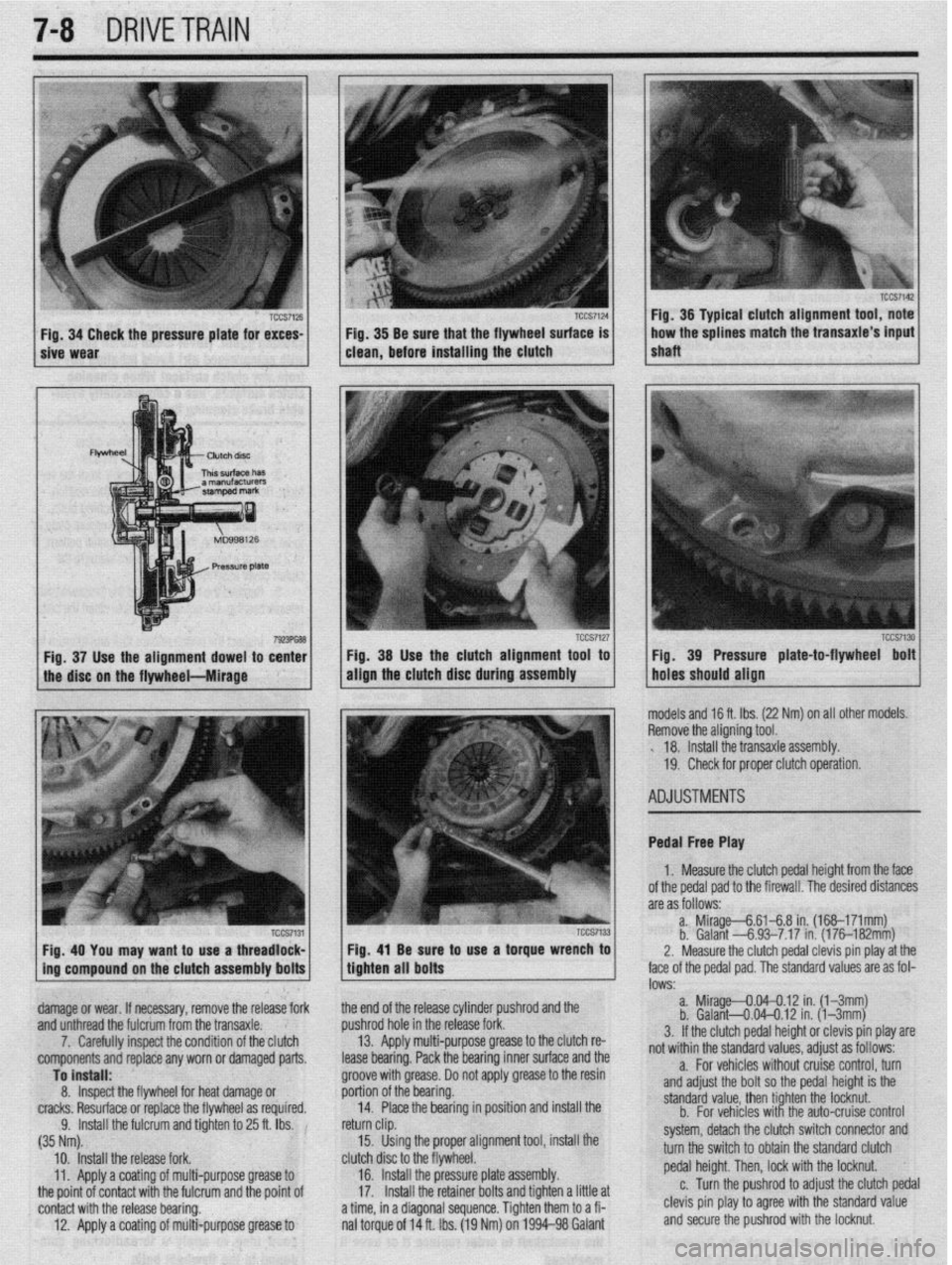
/ sive Wear TCCS7124 1 Fig 34 Check the pressure plate for exces- TCCS7126 j / . Fig 38 Be sure that the flywheel surface is
clean, before installing the clutch
Fig. 38 Use the clutch alignment tool to
align the
clutch disc during assembly
Fig. 40 You may want to use a threadlock- Fig, 41 Be sure to use a torque wrench to
ing compound on the clutch assembly bolts
tighten all bolts
damage or wear. If necessary, remove the release fork the end of the release cylinder pushrod and the
and unthread the fulcrum from the transaxle. pushrod hole in the release fork.
7. Carefully inspect the condition of the clutch 13. Apply multi-purpose grease to the clutch re-
components and replace any worn or damaged parts.
lease bearing. Pack the bearing inner surface and the r Fig. 36 Typical clutch alignment tool, note
shaft ,,, 1 how the splines match the transaxle’s input
TCCS7130 Fig. 39 Pressure plate-to-flywheel bolt
holes should align
nodels and 16 ft. Ibs. (22 Nm) on all other models.
3emove the aligning tool.
. 18. Install the transaxle assembly.
19. Check for proper clutch operation.
4DJUSTMENTS
Pedal Free Play
1. Measure the clutch pedal height from the face
of the pedal pad to the firewall. The desired distances
are as follows:
a. Mirage--&6148 in. (168-171mm)
b. Galant -6.93-7.17 in. (176182mm)
2. Measure the clutch pedal clevis pin play at the
ace of the pedal pad. The standard values are as fol-
DWS: a. Mirage--0.04--0.12 in. (l-3mm)
b. Galant4.04-0.12 in. (l-3mm)
3. If the clutch pedal height or clevis pin play are
rot within the standard values, adjust as follows:
Page 288 of 408
DRIVETRAIN 7-9
*When adjusting the clutch pedal height or
the clutch pedal clevis pin play, be careful
not to push the pushrod toward the master
cylinder.
d. Check that when the clutch pedal is de-
pressed all the way, the interlock switch switches
over from ON to OFF.
ADJUSTMENT
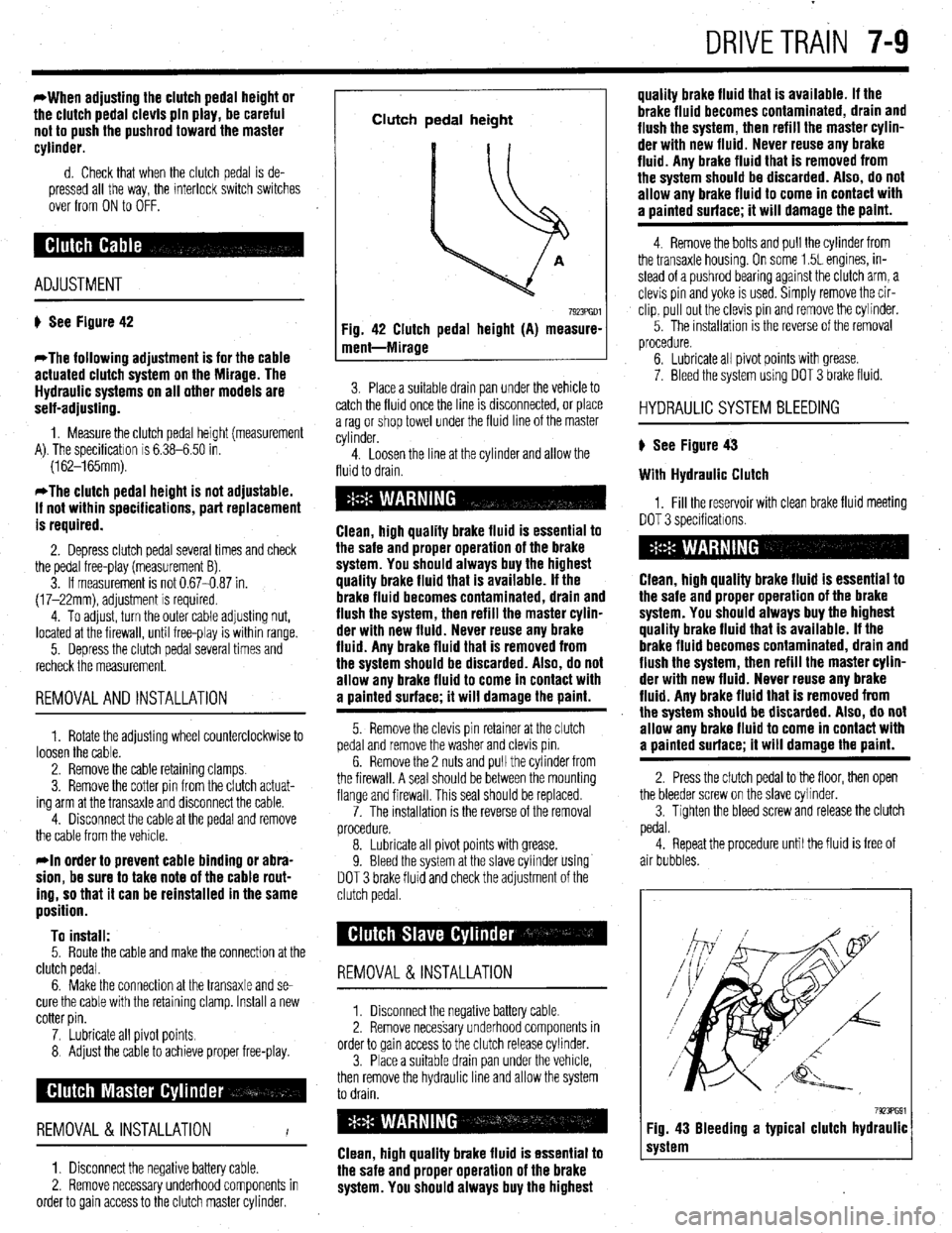
# See Figure 42
*The following adjustment is for the cable
actuated clutch system on the Mirage. The
Hydraulic systems on all other models are
self-adjusting.
1. Measure the clutch pedal height (measurement
A). The specificatron is 6.38-6.50 in.
(162-165mm).
*The clutch pedal height is not adjustable.
If not within specifications, part replacement
is required.
2. Depress clutch pedal several times and check
the pedal free-play (measurement B).
3. If measurement is not 0.67-0.87 in.
(17-22mm), adjustment is required.
4. To adjust, turn the outer cable adjusting nut,
located at the firewall, until free-play is within range.
5. Depress the clutch pedal several times and
recheck the measurement.
REMOVALANDINSTALLATION
1. Rotate the adjusting wheel counterclockwise to
loosen the cable.
2. Remove the cable retaining clamps.
3. Remove the cotter pin from the clutch actuat-
ing arm at the transaxle and disconnect the cable.
4. Disconnect the cable at the pedal and remove
the cable from the vehicle.
rln order to prevent cable binding or abra-
sion, be sure to take note of the cable rout-
ing, so that it can be reinstalled in the same
position.
To install:
5. Route the cable and make the connection at the
clutch pedal.
6. Make the connection at the transaxle and se-
cure the cable with the retaining clamp. Install a new
cotter pin.
7. Lubricate all pivot points.
8 Adjust the cable to achieve proper free-play.
REMOVAL &INSTALLATION
I
1. Disconnect the negative battery cable.
2. Remove necessary underhood components in
order to gain access to the clutch master cylinder.
Clutch pedal height
Fig. 42 Clutch pedal height (A) measure-
ment-Mirage
7923PGDl
3. Place a suitable drain pan under the vehicle to
catch the fluid once the line IS drsconnected, or place
a rag or shop towel under the fluid line of the master
cylinder.
4. Loosen the line at the cylinder and allow the
fluid to drain.
Clean, high quality brake fluid is essential to
the safe and proper operation of the brake
system. You should always buy the highest
quality brake fluid that is available. If the
brake fluid becomes contaminated, drain and
flush the system, then refill the master cylin-
der with new fluid. Never reuse any brake
fluid. Any brake fluid that is removed from
the system should be discarded. Also, do not
allow any brake fluid to come in contact with
a oainted surface; it will damage the paint.
5. Remove the clevis pin retainer at the clutch
pedal and remove the washer and clevis pm.
6. Remove the 2 nuts and pull the cylinder from
the firewall. A seal should be between the mounting
flange and firewall. This seal should be replaced.
7. The installation is the reverse of the removal
procedure.
8. Lubricate all pivot points with grease.
9. Bleed the system at the slave cylinder using
DOT 3 brake fluid and check the adjustment of the
clutch pedal.
REMOVAL &INSTALLATION
1. Disconnect the negative battery cable
2. Remove necessary underhood components in
order to gain access to the clutch release cylinder.
3. Place a suitable drain pan under the vehicle,
then remove the hydraulic line and allow the system
to drain.
Clean, high quality brake fluid is essential to
the safe and proper operation of the brake
system. You should always buy the highest quality brake fluid that is available. If the
brake fluid becomes contaminated, drain and
flush the system, then refill the master cylin-
der with new fluid. Never reuse any brake
fluid. Any brake fluid that is removed from
the system should be discarded. Also, do not
allow any brake fluid to come in contact with
a uainted surface; it will damage the paint.
4. Remove the bolts and pull the cylinder from
the transaxle housing. On some 1.5L engines, in-
stead of a pushrod bearing against the clutch arm, a
clevis pin and yoke is used. Simply remove the cir-
clip, pull out the clevis pin and remove the cylinder.
5. The installation IS the reverse of the removal
procedure.
6. Lubricate all pivot points with grease.
7. Bleed the system using DOT 3 brake fluid.
HYDRAULIC SYSTEM BLEEDING
) See Figure 43
With Hydraulic Clutch
1, Fill the reservoir with clean brake fluid meeting
DOT 3 specificatrons.
Clean, high quality brake fluid is essential to
the safe and proper operation of the brake
system. You should always buy the highest
quality brake fluid that is available. If the
brake fluid becomes contaminated, drain and
flush the system, then refill the master cylin-
der with new fluid. Never reuse any brake
fluid. Any brake fluid that is removed from
the system should be discarded. Also, do not
allow any brake fluid to come in contact with
a painted surface; it will damage the paint.
2. Press the clutch pedal to the floor, then open
the bleeder screw on the slave cvlinder.
3. Tighten the bleed screw and release the clutch
pedal.
4. Repeat the procedure until the fluid is free of
air bubbles.
7923PG91 Fig. 43 Bleeding a typical clutch hydraulic
system
Page 290 of 408
DRIVETRAIN 7-11
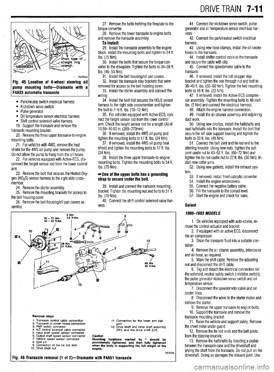
Fig. 45 location of 4-wheel steering oil
l Park/neutral switch electrical harness l Kickdown servo switch l Pulse generator l Oil temperature sensor electrical harness l Shift control solenoid valve harness.
19. Support the transaxle and remove the
transaxle mounting bracket.
20. Remove the three upper transaxle-to-engine
mounting bolts.
21. For vehicles with 4WS, remove the heat
shield for the 4WS oil pump and remove the pump.
Do not allow the pump to hang from the oil hoses.
22. For vehicles equipped with Active-ECS, dis-
connect the height sensor rod from the lower control
arm.
23. Remove the bolt that secures the Heated Oxy-
gen (HOaS) sensor harness to the right side cross-
member.
’ 24. Remove the starter assembly.
25. Remove the mounting brackets for access to
the bell housing cover,
26. Remove the bell housing/oil pan covers as-
sembly. 27. Remove the bolts holding the flexplate to the
torque converter.
28. Remove the lower transaxle to engine bolts
and remove the transaxle assembly.
To install: 29. Install the transaxle assembly to the engine
block, install the mounting bolts and tighten to 54 ft.
tbs. (75 Nm).
30. Install the bolts that secure the torque con-
verter to the driveplate. Tighten the bolts to 34-38 ft.
Ibs (4653 Nm).
31. Install the bell housing/oil pan covers.
32. Install the transaxle stay brackets that were
removed for access to the bell housing cover.
33. Install the starter assembly and connect the
wiring.
34. Install the bolt that secures the HO& sensor
harness to the right side crossmember and tighten
the bolt to 7-9 ft. Ibs. (X-12 Nm).
35. For vehicles equipped with Active-ECS, con-
nect the height sensor rod from the lower control’
arm. Check the height sensor rod for a length (A) of
10.59-10.63 in. (269-270mm)
36. If removed, install the 4WS oil pump and
tighten the mounting bolts to 17 ft. Ibs. (24 Nm).
37. If removed, install the 4WS oil pump heat
shield and tighten the mounting bolts to 17 ft. Ibs.
(24 Nm).
38. Install the three upper transaxle-to-engine
mounting bolts. Tighten the mounting bolts to 54 ft.
Ibs. (75 Nm).
*One of the upper bolts has a grounding
strap to secure under the bolt.
39. Install and connect the transaxle mounting
bracket. Tighten the mounting nut and bolts to 51 ft.
Ibs. (70 Nm).
40. Connect the shift control solenoid valve har-
ness
Removal steps 1. Transaxle control cable connection
2. Transaxle 011 cooler hoses connection
3. PNP swrtch connector
4. FvT control solenoid valve connector
5. Input shaft speed sensor connector
6. Output shaft speed sensor connector
7. Vehicle speed sensor connector
6. Spht pin
9. Connection of the tie rod end
10. Drwe shaft nut 11. Connectton for the lower arm ball
jomt
12. Drwe shaft and inner shaft assembly
(RH) and the drwe shaft (LH)
Caution
Mounting locations marked by
l should be
provisionally tightened, and then fully tightened
when the body is supporting the full weight of the
engine.
7923PG84
:io. 46 Transaxie removal (1 of 2)-Diamante with F4A51 transaxie
41. Connect the kickdown servo switch, pulse
generator and oil temperature sensor electrical har-
ness
42. Connect the park/neutral switch electrical
harness.
43. Using new hose clamps, install the oil cooler
hoses to the transaxle.
44. Install shifter control cable to the transaxle
and secure the cable with clip.
45. Connect the speedometer cable to the
transaxle.
46. If removed, install the roll stopper stay
bracket and tighten the one through nut and bolt to
36-43 ft. Ibs. (50-60 Nm). Tighten the two mounting
bolts to 16 ft. Ibs. (22 Nm).
47. If removed, install the Active-ECS compres-
sor assembly. Tighten the mounting bolts to 48 inch
Ibs. (5 Nm) and connect the electrical harness.
48. Attach the engine harness connection.
49. Install the air cleaner assembly and adjoining
duct work.
50. Using new circlips, install the halfshafts and
seat halfshafts into the transaxle. Install the bolt that
secure the left side support bearing and tighten the
bolts to 33 ft. Ibs. (45 Nm).
51. Connect the ball joint and tie rod end to the
steering knuckle. Using new nuts, tighten the ball
joint castle nut to 43-52 ft. Ibs. (60-72 Nm) and
tighten the tie rod castle nut to 22 ft. ibs. (30 Nm). in-
stall new cotter pins.
52. Using new gaskets, install the exhaust sys-
tem.
53. If removed, install front catalytic converter.
54. Install the engine undercovers.
55. Connect the negative battery cable.
56. Fill the transaxle to the correct level.
57. Start the engine and check for leaks.
Gaiant
1999-1993 MODELS
1. On vehicles equipped with auto-cruise, re-
move the control actuator and bracket.
2. If equipped with an active ECS, disconnect
the air compressor.
3. Drain the transaxle fluid into a suitable con-
tainer.
4. Remove the air cleaner assembly, intercooler
and air hose, as required.
5. Mark the shift cable. Remove the adjusting
nut and disconnect the shift cable.
6. Tag and detach the electrical connectors for
the solenoid, neutral safety switch (inhibitor switch),
the pulse generator kickdown servo switch and oil
temperature sensor.
7. Disconnect the speedometer cable and oil
cooler lines.
8. Disconnect the wires to the starter motor and
remove the starter.
9. Remove the upper transaxle to engine bolts.
10. Support the transaxle and remove the
transaxle mounting bracket.
11. Raise the vehicle and support safely. Remove
the sheet metal under guard
12. Remove the tie rod ends and the bail joints
from the steering knuckle.
13. Remove the halfshafts by inserting a prybar
between the transaxle case and the driveshaft and
prying the shaft from the transaxle. Do not pull on the
driveshaft. Doing so damages the inboard joint. Use
Page 302 of 408
SUSPENSION AND STEERING 8-7
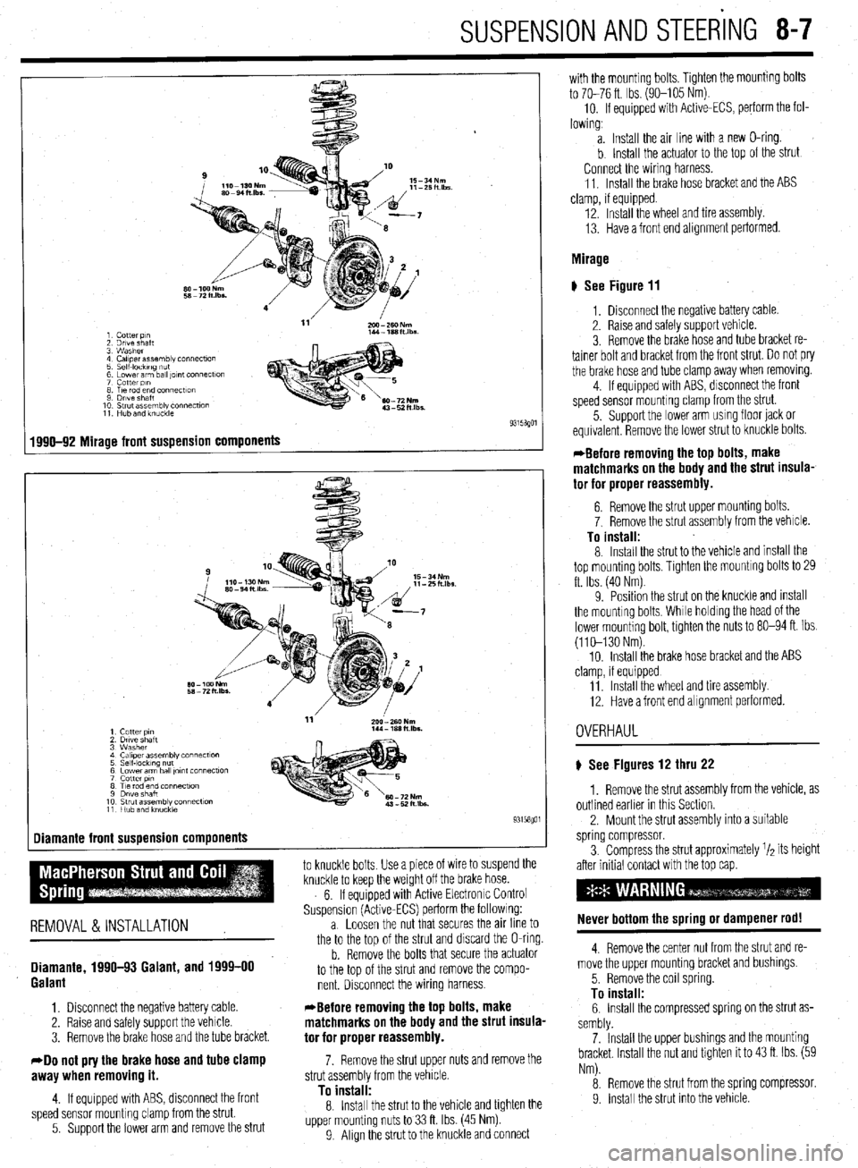
1 Cotter p,n
2 Drive shaft
3 Washer
4 Caliper assembly connecf~on
5 Self-IockIng ““f
6 Lower arm ball ,Ol”f Connectlo”
7 cotter PI”
8 T,e rod end connectton
9 Drive Shaft
10 Strut assembly connection
11 Hub and knuckle
1990-92 Mirage front suspension components
-
1 Cutter PI”
2 Drtve shaft
3 Washer
4 Ca,,perassembly connect~o”
5 Self-locking nut
6 Lower arm ball ,o,nt connection
7 cotter PI”
8 Tie rod end connection
9 Dwe shaft
10 Strut assembly connection
11 Hub and knuckie
Diamante front suspension components
1
to knuckle bolts Use a piece of wire to suspend the
knuckle to keep the weight off the brake hose.
6. If equipped with Active Electronrc Control
Suspension (Active-ECS) perform the followrng:
REMOVAL &INSTALLATION a. Loosen the nut that secures the an line to
the to the too of the strut and discard the O-ring.
Diamante, 1990-93 Galant, and 1999-00
Galant
1. Disconnect the negative battery cable.
2. Raise and safely support the vehicle.
3. Remove the brake hose and the tube bracket.
40 not pry the brake hose and tube clamp
awav when removino it.
b. Remove the bolts that secure the actuator
to the top of the strut and remove the compo-
nent. Disconnect the wiring harness.
*Before removing the top bolts, make
matchmarks on the body and the strut insula-
tor for proper reassembly.
7. Remove the strut upper nuts and remove the
strut assemblv from the vehicle.
4. If equipped with ABS, disconnect the front
speed sensor mounting clamp from the strut.
5. Support the lower arm and remove the strut
To instalf: 8. Install the strut to the vehicle and tighten the
upper mounting nuts to 33 ft. Ibs. (45 Nm)
9 Align the strut to the knuckle and connect with the mounting bolts. Tighten the mounting bolts
to 70-76 ft. Ibs. (90-105 Nm).
10. If equipped with Active-ECS, perform the fol-
lowing,
a. Install the air line with a new O-ring.
b Install the actuator to the top of the strut
Connect the wiring harness.
11. Install the brake hose bracket and the ABS
clamp, if equipped.
12. Install the wheel and tire assembly.
13. Have a front end alignment performed.
Mirage
# See Figure 11
1, Disconnect the negative battery cable.
2. Raise and safely support vehicle.
3. Remove the brake hose and tube bracket re-
tainer bolt and bracket from the front strut. Do not pry
the brake hose and tube clamp away when removrng.
4. If equipped with ABS, disconnect the front
speed sensor mounting clamp from the strut.
5. Support the lower arm usmg floor jack or
equivalent Remove the lower strut to knuckle bolts.
*Before removing the top bolts, make
matchmarks on the body and the strut insula-
tor for proper reassembly.
6. Remove the strut upper mounting bolts.
7. Remove the strut assembly from the vehicle.
To install: 8. Install the strut to the vehicle and install the
top mounting bolts, Tighten the mountrng bolts to 29
ft. Ibs. (40 Nm)
9. Position the strut on the knuckle and mstall
the mounting bolts, While holdrng the head of the
lower mounting bolt, tighten the nuts to 80-94 ft. Ibs.
(110-130 Nm).
10. Install the brake hose bracket and the ABS
clamp, if equipped
11 Install the wheel and tire assembly
12. Have a front end alignment performed.
OVERHAUL
) See Figures 12 thru 22
1. Remove the strut assembly from the vehicle, as
outlined earlier in this Section.
2. Mount the strut assembly into a suitable
spring compressor.
3. Compress the strut approximately r/a its height
after initial contact with the top cap.
Never bottom the spring or dampener rod!
4. Remove the center nut from the strut and re-
move the upper mounting bracket and bushings.
5. Remove the coil spring.
To install: 6. Install the compressed spring on the strut as-
sembly.
7. Install the upper bushings and the mounting
bracket Install the nut and tighten it to 43 ft. Ibs. (59
Nm).
8. Remove the strut from the spring compressor.
9. Install the strut into the vehrcle