1900 MITSUBISHI DIAMANTE wheel alignment
[x] Cancel search: wheel alignmentPage 25 of 408
.
1-26 GENERALINFORMATIONAND MAINTENANCE
TDC of the compression stroke. If this happens, the
piston WIII be at the beginning of the power stroke
just as the compressed and ignited air/fuel mixture
forces the piston down and turns the crankshaft. Be-
cause it takes a fraction of a second for the spark
plug to ignite the mixture in the cylinder, the spark
plug must fire a little before the piston reaches TDC.
Otherwise, the mixture will not be completely ignited
as the piston passes TDC and the full power of the
explosion will not be used by the engine.
The timing measurement is given in degrees of
crankshaft rotation before the piston reaches TDC
(BTDC). If the setting for the ignition timing is 10”
BTDC, each spark plug must fire 10 degrees before
each piston reaches TDC. This only holds true, how-
ever, when the engine is at idle speed. The combus-
tion process must be complete by 23”ATDC to main-
tain proper engine performance, fuel mileage, and
low emissions.
As the engine speed increases, the pistons go
faster. The spark plugs have to ignite the fuel even
sooner if it IS to be completely ignited when the pis-
ton reaches TDC. If the ignition is set too far ad-
vanced (BTDC), the ignition and expansion of the fuel
in the cylinder wtll occur too soon and tend to force
the piston down while it is still traveling up. Thus
causes pre ignition or “knockmg and pinging”. If the
ignition spark is set too far retarded, or after TDC
(ATDC), the piston will have already started on its
way down when the fuel is ignited. The piston will be
forced down for only a portion of its travel, resulting
in poor engine performance and lack of power.
Timing marks or scales can be found on the rim of
the crankshaft pulley and the timing cover. The marks
on the pulley correspond to the posrtion of the piston
in the No. 1 cylinder. A stroboscopic (dynamic) tim-
ing light is hooked onto the No. 1 cylinder spark plug
wrre. Every time the spark plug fires, the timing light
flashes. By aiming the light at the timing marks while
the engine is running, the exact position of the piston
within the cylinder can be easily read (the flash of
light makes the mark on the pulley appear to be
standing still). Proper timing is indicated when the
mark and scale are in specified alignment.
When checking timing with the engine run-
ning, take care not to get the timing light
wires tangled in the tan blades and/or drive
belts.
INSPECTION &ADJUSTMENT
1990-96 Models
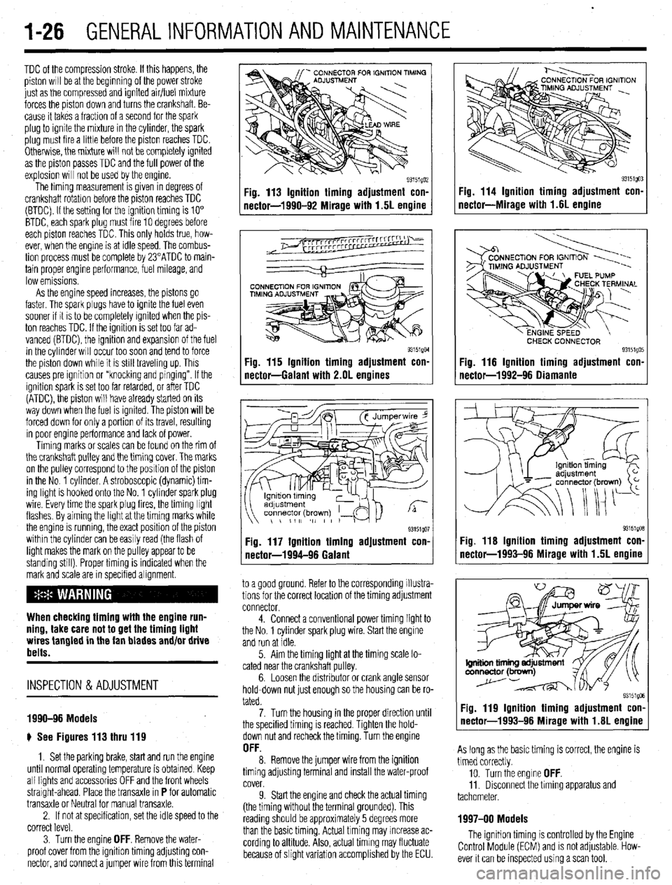
e See Figures 113 thru 119
1. Set the parking brake, start and run the engine
until normal operating temperature is obtained. Keep
all lights and accessories OFF and the front wheels
straight-ahead. Place the transaxle in
P for automatic
transaxle or Neutral for manual transaxle.
2. If not at specification, set the idle speed to the
correct level.
3. Turn the engine
OFF. Remove the water-
proof cover from the igmtion timing adjusting con-
nector, and connect a jumper wire from this terminal
Fig. 113 Ignition timing adjustment con-
nector-1990-92 Mirage with 1.5L engine
93151QM Fig. 115 Ignition timing adjustment con-
nectar-Galant with 2.OL engines
93151QO1 Fig. 117 Ignition timing adjustment con.
nectar-1994-96 Galant
to a good ground. Refer to the corresponding illustra-
tions for the correct location of the timing adjustment
connector.
4. Connect a conventional power timing light to
the No. 1 cylinder spark plug wire. Start the engine
and run at idle.
5. Aim the timing light at the timing scale lo-
cated near the crankshaft pulley.
6. Loosen the distributor or crank angle sensor
hold-down nut just enough so the housing can be ro-
tated.
7. Turn the housing in the proper direction until
the specified timing is reached. Tighten the hold-
down nut and recheck the timing. Turn the engine
OFF. 8. Remove the jumper wire from the ignition
timing adjusting terminal and install the water-proof
cover.
9. Start the engine and check the actual timing
(the timing without the terminal grounded). This
reading should be approximately 5 degrees more
than the basic timing. Actual timing may increase ac-
cording to altitude. Also, actual timing may fluctuate
because of slight variation accomplished by the ECU.
Fig. 114 Ignition timing adjustment con-
nectar-Miracle with 1.6L enaine
CHECK CONNECTOR 93151QO! Fig. 116 Ignition timing adjustment con.
nectar-1992-96 Oiamante
93151gOB Fig. 116 Ignition timing adjustment con-
nector-1993-96 Mirage with 1.5L engine
Fig. 119 Ignition timing adjustment con-
nector-1993-96 Mirage with 1.6L engine
As long as the basic timing is correct, the engine is
timed correctly.
10. Turn the engine
OFF. 11. Disconnect the timing apparatus and
tachometer.
1997-00 Models
The ignition timing is controlled by the Engine
Control Module (ECM) and is not adjustable. How-
ever it can be inspected using a scan tool.
Page 29 of 408
.
l-30 GENERAL'INFORMATIONAND MAINTENANCE
n Pylon@ inserts, the clip
be removed prior to siidi then the insert can be re
After installing the replacement
strip and pull up while twisting counterclockwise.
The backing strip will snap out of the retaining tab.
Do this for the remaining tabs until the refill is free of
the blade. The length of these refills is molded into
the end and they should be replaced with identical
types. cate the front end is out of alignment or that the tires
are out of balance.
TIRE ROTATION
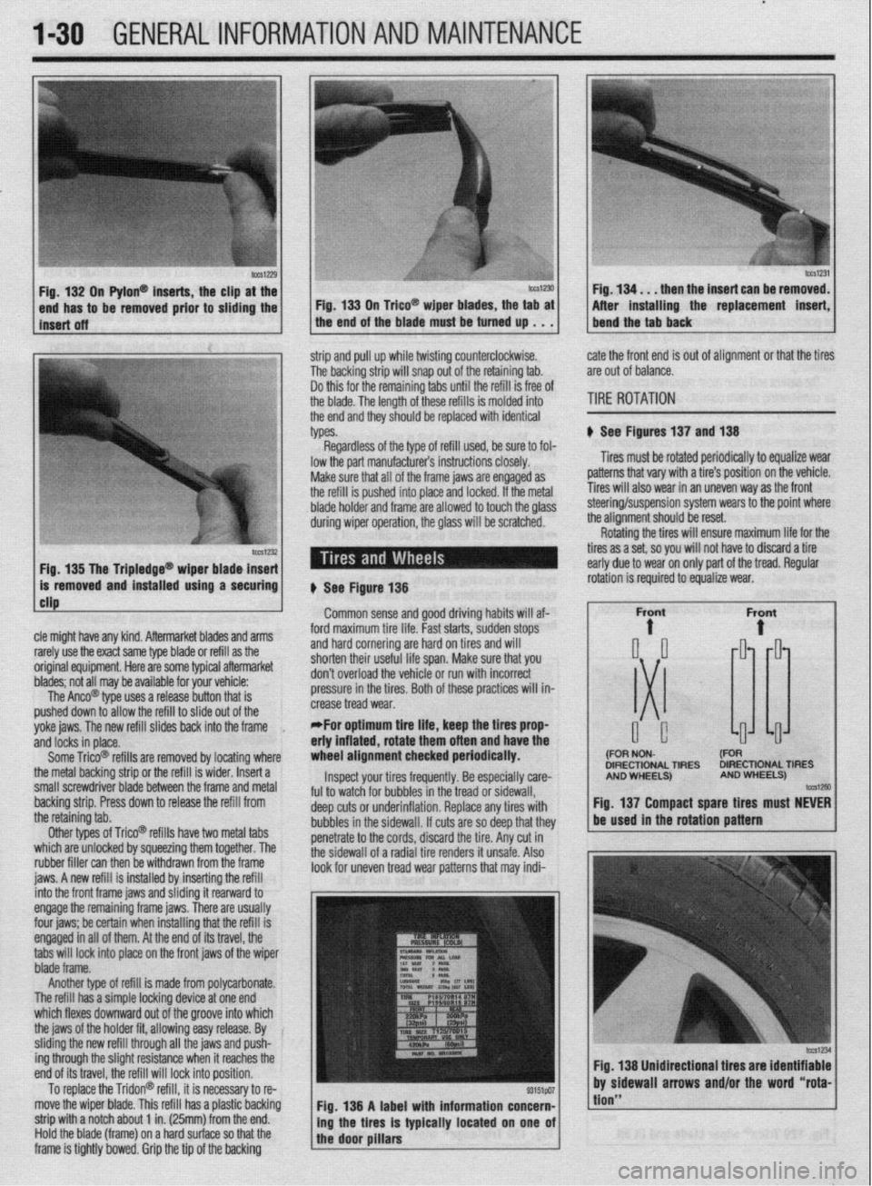
# See Figures 137 and 138
Tires must be rotated periodically to equalize wear
patterns that vary with a tire’s position on the vehicle.
Tires will also wear in an uneven way as the front
1 Fin 1% Tha Trinlarlna@
cle might have any kind. Aftermarket blades and arms
rarely use the exact same type blade or refill as the
original equipment. Here are some typiel aftermarket
blades; not all may be available for your vehicle:
The Anco@ type uses a release button that is
pushed down to allow the refill to slide out of the
yoke jaws. The new refill slides back into the frame
,
and locks in place.
Some Trico@ refills are removed by locating where
the metal backing strip or the refill is wider. Insert a
small screwdriver blade between the frame and metal
backing strip. Press down to release the refill from
the retaining tab.
Other types of Trico@’ refills have two metal tabs
which are unlocked by squeezing them together. The
rubber filler can then be withdrawn from the frame
iaws. A new refill is installed bv insertina the refill lowed to touch the olass steering/suspension system wears to the point where
the alianment should be reset.
# See Figure 138
Common sense and good driving habits will af-
ford maximum tire life. Fast starts, sudden stops
and hard cornering are hard on tires and will
shorten their useful life span. Make sure that you
don’t overload the vehicle or run with incorrect
pressure in the tires. Both of these practices will in-
crease tread wear.
*For optimum tire life, keep the fires prop
eriy inflated, rotate them often and have the
wheel alignment checked periodically.
Inspect your tires frequently. Be especially care-
ful to watch for bubbles in the tread or sidewall,
deep cuts or underinflation. Replace any tires with
bubbles in the sidewall. If cuts are so deep that they
penetrate to the cords, discard the tire. Any cut in
the sidewall of a radial tire renders it unsafe. Also
look for uneven tread wear patterns that may indi- Rotating the tires will ensure maximum life for the
tires as a set, so you will not have to discard a tire
early due to wear on only part of the tread. Regular
DIRECTIONAL TIRES DIRECTIONAL TIRES
jnto the front frame jaws and &ding it rearward to
engage the remaining frame jaws. There are usually
four jaws; be certain when installing that the refill is
engaged in all of them. At the end of its travel, the
tabs will lock into place on the front jaws of the wiper
blade frame.
Another type of refill is made from polycarbonate.
The refill has a simple locking device at one end
which flexes downward out of the groove into which
the jaws of the holder fit, allowing easy release. By
sliding the new refill through all the jaws and push-
ing through the slight resistance when it reaches the
end of its travel, the refill will lock into position.
To replace the Tridon@ refill, it is necessary to re-
move the wiper blade. This refill has a plastic backing
strip with a notch about 1 in. (25mm) from the end.
Hold the blade (frame) on a hard surface so that the
frame is tightly bowed. Grip the tip of the backing Fig. 138 A label with information concern-
ing the tires is typically located on one of
the door pillars
tion”
Page 31 of 408
.
1-32 GENERALINFORMATIONAND MAINTENANCE
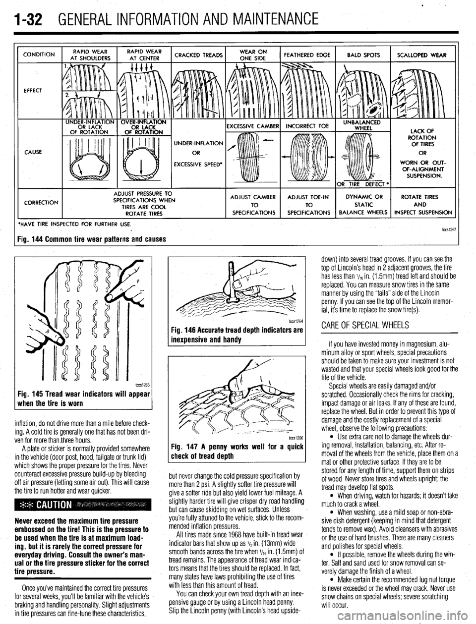
CONDITION
EFFECT
CAUSE
CORRECTION UNDER-INFLATION
EXCESSIVE SPEED’ WORN OR OUT-
OF-ALIGNMENT
ADJUST PRESSURE TO
SPECIFICATIONS WHEN
TIRES ARE COOL
ROTATE TIRES
/ BALANCE WHEELS INSPECT SUSPENSION
HAVE TIRE INSPECTED FOR FURTHER USE.
lCCSi267 ig. 144 Common tire wear patterns and causes
1~~~1265 Fig. 145 Tread wear indicators will appear
when the tire is worn
inflation, do not drive more than a mile before check-
ing. A cold tire is generally one that has not been dri-
ven for more than three hours.
A plate or sticker is normally provided somewhere
in the vehicle (door post, hood, tailgate or trunk lid)
which shows the proper pressure for the tires. Never
counteract excessive pressure build-up by bleeding
off air pressure (letting some air out). This will cause
the tire to run hotter and wear quicker.
Never exceed the maximum tire pressure
embossed on the tire! This is the pressure to
be used when the tire is at maximum load-
ing, but it is rarely the correct pressure for
everyday driving. Consult the owner’s man-
ual or the tire pressure sticker for the correct
tire pressure.
Once you’ve maintained the correct tire pressures
for several weeks, you’ll be familiar with the vehicle’s
braking and handling personality. Slight adjustments
in tire pressures can fine-tune these characteristics,
1~~~1264 Fig. 146 Accurate tread depth indicators are
inexuensive and handv
Fig. 147 A penny works well for a quick
check of tread death
but never change the cold pressure specification by
more than 2 psi. A slightly softer tire pressure will
give a softer ride but also yield lower fuel mileage. A
slightly harder tire will give crisper dry road handling
but can cause skidding on wet surfaces. Unless
you’re fully attuned to the vehicle, stick to the recom-
mended inflation pressures.
All tires made since 1968 have built-in tread wear
indicator bars that show up as j/2 in. (13mm) wide
smooth bands across the bre when V,~ in. (1.5mm) of
tread remains. The appearance of tread wear indica-
tors means that the tires should be replaced. In fact,
many states have laws prohibiting the use of tires
with less than this amount of tread.
You can check your own tread depth with an inex-
pensive gauge or by using a Lincoln head penny.
Shp the Lrncoln penny (with Lincoln’s head upside- down) into several tread grooves. If you can see the
top of Lincoln’s head in 2 adjacent grooves, the tire
has less than V,~ in. (1.5mm) tread left and should be
replaced. You can measure snow tires in the same
manner by using the “tails” side of the Lincoln
penny. If you can see the top of the Lincoln memor-
ial, its time to replace the snow tire(s).
CAREOFSPECIALWHEELS
If you have invested money in magnesium, alu-
minum alloy or sport wheels, special precautions
should be taken to make sure your investment is not
wasted and that your special wheels look good for the
life of the vehicle.
Special wheels are easily damaged and/or
scratched. Occasionally check the rims for cracking,
impact damage or air leaks. If any of these are found,
replace the wheel. But in order to prevent this type of
damage and the costly replacement of a special
wheel, observe the following precautions:
l Use extra care not to damage the wheels dur-
ing removal, installation, balancing, etc. After re-
moval of the wheels from the vehicle, place them on a
mat or other protective surface. If they are to be
stored for any length of time, support them on strips
of wood. Never store tires and wheels upright; the
tread may develop flat spots.
l When driving, watch for hazards; it doesn’t take
much to crack a wheel.
l When washing, use a mild soap or non-abra-
sive dish detergent (keeping in mind that detergent
tends to remove wax). Avoid cleansers with abrasives
or the use of hard brushes. There are many cleaners
and polishes for special wheels.
l If possrble, remove the wheels during the win-
ter. Salt and sand used for snow removal can se-
verely damage the finish of a wheel.
l Make certain the recommended lug nut torque
is never exceeded or the wheel may crack. Never use
snow chains on special wheels; severe scratching
will occur.
Page 126 of 408
I)
ENGINEANDENGINEOVERHAUL 3-65
10. Install the camshaft(s), rockers, shafts and
any other components that were removed for disas-
sembly.
GENERAL INFORMATION ways number 1. However, depending on the engine
placement, the front of the engine could either be the
flywheel or damper/pulley end. Generally the front of
the engine faces the front of the vehicle. Use a num-
ber punch or scribe and also mark the main bearing
caps from front to rear with the front most cap being
number 1 (if there are five caps, mark them 1 through
5, front to rear).
A thorough overhaul or rebuild of an engine block
would include replacing the pistons, rings, bearings,
timing belt/chain assembly and oil pump. For OHV
engines also include a new camshaft and lifters. The
block would then have the cylinders bored and honed
oversize (or if using removable cylinder sleeves, new
sleeves installed) and the crankshaft would be cut
undersize to provide new wearing surfaces and per-
feet clearances. However, your particular engine may Take special care when pushing the connect-
ing rod up from the crankshaft because the
sharp threads of the rod bolts/studs will
score the crankshaft journal. Insure that spe-
cial plastic caps are installed over them, or
cut two pieces of rubber hose to do the
same.
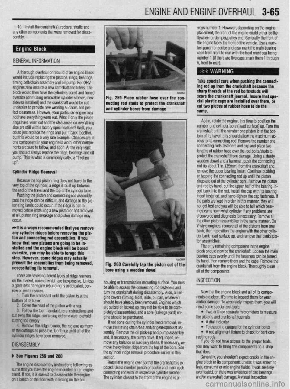
Again, rotate the engine, this time to position the
number one cylinder bore (head surface) up. Turn the
crankshaft until the number one piston is at the bot-
tom of its travel, this should allow the maximum ac-
cess to its connecting rod. Remove the number one
connecting rods fasteners and cap and place two
lengths of rubber hose over the rod bolts/studs to
protect the crankshaft from damage. Using a sturdy
wooden dowel and a hammer, push the connecting
rod up about 1 in. (25mm) from the crankshaft and
remove the upper bearing insert. Continue pushing
or tapping the connecting rod up until the piston
rings are out of the cylinder bore. Remove the piston
and rod by hand, put the upper half of the bearing in-
sert back into the rod, install the cap with its bearing
insert installed, and hand-tighten the cap fasteners. If
the parts are kept in order in this manner, they will
not get lost and you will be able to tell which bear-
ings came form what cylinder if any problems are
discovered and diagnosis is necessary. Remove all
the other piston assemblies in the same manner. On
V-style engines, remove all of the pistons from one
bank, then reposition the engine with the other cylin-
der bank head surface up, and remove that banks nis-
prevent the assemblies from being removed,
necessitating its removal. Fig. 260 Carefully tap the piston out of the
bore using a wooden dowel
There are several different types of ridge reamers
on the market, none of which are inexpensive, Unless
.3 “me.+ ,-ins, rdnnn;nn mh~lil.-linn ;I nn+:n:nnL.* l.^W
a ylwx “Gal “I cllylllc Ir;““ll”llly 13 dllLILlpxC”, ““I- row or rent a reamer.
1. Turn the crankshaft until the piston is at the
bottom of its travel.
2. Cover the head of the piston with a rag.
3. Follow the tool manufacturers instructions and housing or transmission mounting surface. You must
1 as many
II of the
~1SA~E~BLY
b See Figures 259 and 260
The engine disassembly instructions following as-
sume that you have the engine mounted on an engine
stand. If not, it is easiest to disassemble the engine
on a bench or the floor with it resting on the bell be able to access the connecting rod fasteners and
turn the crankshaft during disassembly. Also, all en-
gine covers (timing, front, side, oil pan, whatever)
should
are sei2
nletelv have already been removed. Engines which
,ed or locked up may not be able to be com-
r’-‘-‘, disassembled, and a core (salvage yard) en-
gine sh ould be purchased.
If no
t done during the cylinder head removal, re-
move the timing chain/belt and/or gear/sprocket as-
sembly. Remove the oil pick-up and pump assembly
and, if necessary, the pump drive. If equipped, re-
move any balance or auxiliary shafts. If necessary, re-
move the cylinder ridge from the top of the bore. See
the cylinder ridge removal procedure earlier in this
section.
Rotate the engine over so that the crankshaft is ex-
posed. Use a number punch or scribe and mark each
connecting rod with its respective cylinder number.
The cylinder closest to the front of the engine is al- cut away the ridge, exercising extreme care to avoid
~ ioo deepfy.
4. Remove the ridge reamer, the rag and
armings as possible. Continue until a
biter ridges have been removed. ton assemblies.
The only remaining component in the engine
block should now be the crankshaft. Loosen the main
bearing caps evenly until the fasteners can be turned
by hand, then remove them and the caps. Remove the
crankshaft from the engine block. Thoroughly clean
all of the components.
INSPECTION
Now that the engine block and all of its compo-
nents are clean, it’s time to inspect them for wear
and/or damage. To accurately inspect them, you will
need some specialized tools:
l Two or three separate micrometers to measure
the prstons and crankshaft journals
l A dial indicator l Telescoping gauges for the cylinder bores l A rod alignment fixture to check for bent con-
netting rods
If you do not have access to the proper tools,
you may want to bring the components to a shop
that does.
Generally, you shouldn’t expect cracks in the en-
gine block or its components unless it was known to
leak, consume or mix engine fluids, it was severely
overheated, or there was evidence of bad bearings
and/or crankshaft damage. A visual inspection
Page 287 of 408
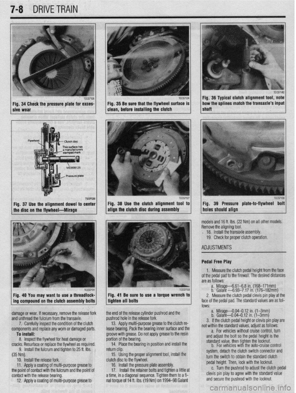
7-8 DRIVETRAIN
/ sive Wear TCCS7124 1 Fig 34 Check the pressure plate for exces- TCCS7126 j / . Fig 38 Be sure that the flywheel surface is
clean, before installing the clutch
Fig. 38 Use the clutch alignment tool to
align the
clutch disc during assembly
Fig. 40 You may want to use a threadlock- Fig, 41 Be sure to use a torque wrench to
ing compound on the clutch assembly bolts
tighten all bolts
damage or wear. If necessary, remove the release fork the end of the release cylinder pushrod and the
and unthread the fulcrum from the transaxle. pushrod hole in the release fork.
7. Carefully inspect the condition of the clutch 13. Apply multi-purpose grease to the clutch re-
components and replace any worn or damaged parts.
lease bearing. Pack the bearing inner surface and the r Fig. 36 Typical clutch alignment tool, note
shaft ,,, 1 how the splines match the transaxle’s input
TCCS7130 Fig. 39 Pressure plate-to-flywheel bolt
holes should align
nodels and 16 ft. Ibs. (22 Nm) on all other models.
3emove the aligning tool.
. 18. Install the transaxle assembly.
19. Check for proper clutch operation.
4DJUSTMENTS
Pedal Free Play
1. Measure the clutch pedal height from the face
of the pedal pad to the firewall. The desired distances
are as follows:
a. Mirage--&6148 in. (168-171mm)
b. Galant -6.93-7.17 in. (176182mm)
2. Measure the clutch pedal clevis pin play at the
ace of the pedal pad. The standard values are as fol-
DWS: a. Mirage--0.04--0.12 in. (l-3mm)
b. Galant4.04-0.12 in. (l-3mm)
3. If the clutch pedal height or clevis pin play are
rot within the standard values, adjust as follows:
Page 292 of 408
DRIVETRAIN 7-13
27. Shde the transaxle rearward and carefully
lower it from the vehicle.
To install: 28. After the torque converter has been mounted
on the transaxle, install the transaxle assembly to the
engine. Install the mounting bolts and tighten to 35
ft. Ibs. (48 Nm).
29. Install the transaxle lower coupling bolt and
tighten to 21-25 ft Ibs. (29-34 Nm).
30. Connect the torque converter to the flexplate
and tighten the bolts to 33-38 ft. Ibs. (45-52 Nm).
31. Install the cover to the transaxle bellhous-
ing and tighten the mounting bolts to 7 ft. Ibs. (9
Nm).
32 Install the crossmember and tighten the front
mounting bolts to 65 ft. Ibs (88 Nm) and the rear
bolt to 54 ft. Ibs. (73 Nm) Install the front engine roll
stopper through-bolt and lightly tighten. Once the full
weight of the engine is on the mounts, tighten the ’
bolt to 42 ft. Ibs. (57 Nm),
33. Install the triangular stay bracket and tighten
the mounting bolts to 65 ft. Ibs. (88 Nm).
34. Install the halfshafts, using new circlips on
the axle ends.
When installing the axleshaft, keep the in-
board joint straight in relation to the axle, so
as not to damage the oil seal lip of the
transaxle with the serrated part of the half-
shaft.
35. Connect the tie rod and ball joints to the
steering knuckle. Tighten the ball joint self-locking
nuts to 48 ft. Ibs. (65 Nm). Tighten the tie rod end nut
to 21 ft. Ibs. (28 Nm) and secure with a new cotter
pin.
36. Connect the damper fork to the lower control
arm and tighten the through-bolt to 65 ft Ibs. (88
Nm).
37. Connect the stabilizer link to the damper fork,
and tighten the self-locking nut to 29 ft. Ibs. (39 Nm).
38. Install the undercover.
39. Install the wheels and carefully lower the ve-
hicle
40. Install the transaxle mount bracket to the
transaxle, and tighten the mounting nuts to 32 ft. Ibs.
(43 Nm).
41. Install the rear roll stopper mounting bracket.
42. Remove the engine support. Tighten the
transaxle mount through-bolt to 51 ft. Ibs. (69 Nm)
and tighten the front engine roll stopper through-bolt.
43. Install the upper transaxle mounting bolts
and tighten to 35 fl. Ibs. (48 Nm).
44. Install the starter motor.
45. Install the dipstick tube and the dipstick
46. Install the shifter cable mounting bracket.
47. Connect the shifter lever and tighten the re-
taining nut to 14 ft. Ibs. (19 Nm).
48. Connect the oil cooler lines and secure with
clamps.
49. Attach the electrical connectors for the
speedometer, solenoid, neutral safety switch (in-,
hibitor switch), the pulse generator, kickdown servo
switch and oil temperature sensor.
50. Install the air cleaner and the air intake hose.
51. Connect the negative battery cable.
52. Make sure the vehicle is level, and refill the
transaxle. Start the engine and allow to idle for 2 minutes. Apply parking brake and move selector
through each gear position, ending in N. Recheck
fluid level and add if necessary. Fluid level should be
between the marks in the HOT range.
53. Check the transaxle for proper operation.
Make sure the reverse lights come on when in re-
verse and the engine starts only in
P or N.
Mirage
*If the vehicle is going to be rolled on its
wheels while the halfshafts are out of the ve-
hicle, obtain two outer CV-joints or proper
equivalent tools and install to the hubs. If the
vehicle is rolled without the proper torque
applied to the front wheel bearings, the bear-
ings will no longer be usable.
1. Disconnect the negative battery cable then
the positive battery cable.
2. Remove the battery and battery tray.
3. Remove the air hose and air cleaner assem-
bly.
4. Raise the vehicle and support safely.
5. Remove the under guard pan.
6. Drain the transaxle oil into a suitable con-
tainer.
7. If equipped with 1.6L engine, remove the ten-
sion rod.
8. Disconnect the control cable and cooler
lines.
9. On 3-speed transaxles, disconnect the throt-
tle control cable.
10. On 4-speed transaxles, perform the following:
a. Detach the shift control solenoid valve
connector.
b. Disconnect the inhibitor switch and kick-
down servo switch.
c. Disconnect the pulse generator and oil
temperature sensor.
11. Disconnect the speedometer cable and re-
move the starter.
12. Remove the transaxle mounting bolts and
bracket.
13. Disconnect the stabilizer bar from the lower
control arm.
14. Disconnect the steering tie rod end and the
ball joint from the steering arm.
15. Remove the halfshafts at the inboard side
from the transaxle. Tie the joint assembly aside.
*It is not necessary to disconnect the half-
shafts from the wheel hubs.
16. Support the engine and remove the center
member.
17. Remove the bellhousing cover and remove
the driveplate bolts.
18 Remove the transaxle assembly lower con-
necting bolt, located just over the halfshaft opening.
19. Properly support the transaxle assembly, then
lower it, moving it to the right for clearance.
To install: 20. After the torque converter has been mounted
on the transaxle, install the transaxle assembly on the
engine. Install the mounting bolts and tighten to
31-40 ft. Ibs. (43-55 Nm) on 1990-92 models and
35 ft. Ibs. (48 Nm) on 1993-00 models.
21. Tighten the driveplate bolts to 33-38 ft. Ibs.
(46-53 Nm). Install the bellhousing cover.
22. Install the center member. 23. Replace the circlips and install the halfshafts
to the transaxle.
24. Install the tie rods, ball joints and stabilizer
links to the steering arm
25. Install the transaxle mounting bracket and
bolts.
26. Install the starter.
27. Connect the speedometer cable.
28. Connect the inhibitor switch, kickdown servo
switch, the pulse generator and oil temperature sen-
sor, if disconnected.
29. Connect the shift control solenoid valve con-
nector.
30. Connect the control cables and oil cooler
lines.
31. Install the tension rod, if removed.
32. Install the air cleaner assembly.
33. Install the battery tray and battery.
34. Connect the positive then the negative termi-
nal.
35. Refill with Dexron@ II, Mopar ATF Plus type
7176 or equivalent, automatic transaxle fluid.
36. Start the engine and allow to idle for two min-
utes. Apply parking brake and move selector through
each gear position, ending in N. Recheck fluid level
and add if necessary. Fluid level should be between
the marks in the HOT range.
ADJUSTMENTS
Shifter Control Cable Adjustment
1. The shifter cable adjustment is done at the
neutral safety switch (inhibitor switch). Locate the
switch on the transaxle and note the alignment holes
in the arm and the body of the switch. Place the se-
lector lever in N. Place the manual lever of the
transaxle in the neutral position.
2. Check alignment of the hole in the manual
control lever to the hole in the inhibitor switch body.
If the holes do not align, adjustment is required.
3. To adjust, loosen the nut on the cable end and
pull the cable end by hand until the alignment holes
match. Tighten the nut. Check that the transaxle
shifts and conforms to the positions of the selector
lever.
Throttle Valve Cable
The throttle valve adjustment applies only to the
1990-96 Mirage.
1. Place selector lever and manual control lever
in N position.
2. Loosen adjusting nut. While lightly pulling on
control cable tighten mounting nut to 7-10 ft. Ibs.
(X-14 Nm).
3. When adjustment is complete, be sure selector
lever is still in the N position. Verify all functions
correspond to the position indicated on the selector
lever.
The halfshaft removal and installation and over-
haul are the same as a manual transaxle Please refer
to Manual Transaxle in this Section
Page 296 of 408
WHEELS 8-2
WHEEL ASSEMBLY 8-2
REMOVAL & INSTALLATION 8-2
INSPECTION 8-2
WHEELLUG STUDS 8-2
REMOVAL & INSTALLATION 8-2
FRONT SUSPENSION 8-4
MACPHERSONSTRUTAND COIL
SPRING 8-7
REMOVAL & INSTALLATION 8-7
OVERHAUL 8-7
SHOCKABSORBERAND COIL
SPRING 8-8
REMOVAL &INSTALLATION 8-8
OVERHAUL 8-9
UPPER BALLJOINT 8-9
REMOVAL & INSTALLATION 8-9
INSPECTION 8-9
UPPER CONTROLARM 8-10
REMOVAL &INSTALLATION 8-10
LOWER BALLJOINT 8-10
REMOVAL &INSTALLATION 8-10
INSPECTION 8-10
LOWER CONTROL ARM 8-10
REMOVAL&INSTALLATION 8-10
SWAY BAR 8-12
REMOVAL & INSTALLATION 8-12
KNUCKLE, HUB, AND BEARING 8-13
REMOVAL & INSTALLATION 8-13
WHEEL ALIGNMENT 8-16
CASTER 8-16
CAMBER 8-17
TOE 8-17
REAR SUSPENSION 8-18
STRUT AND COIL SPRING 8-21
REMOVAL & INSTALLATION 8-21
OVERHAUL 8-22
UPPER CONTROLARMS 8-22
REMOVAL & INSTALLATION 8-22
LOWER CONTROL ARMS 8-23
REMOVAL &INSTALLATION 8-23
TRAINING ARM 8-24
REMOVAL & INSTALLATION 8-24
SWAY BAR 8-25
REMOVAL &INSTALLATION 8-25
HUB & BEARINGS 8-25
ADJUSTMENT 8-25
REMOVAL & INSTALLATION 8-25
STEERING 8-27
STEERING WHEEL 8-27
REMOVAL &INSTALLATION 8-27
COMBINATION SWITCH 8-29
REMOVAL &INSTALLATION 8-29
WINDSHIELD WIPER SWITCH 8-29
REMOVAL&INSTALLATION 8-29
IGNITION LOCK CYLINDER 8-29 '
REMOVAL &INSTALLATION 8-29
IGNITION SWITCH 8-30
REMOVAL &INSTALLATION 8-30
STEERING LINKAGE 8-30
REMOVAL&INSTALLATION 8-30
MANUAL RACK AND PINION STEERING
GEAR 8-31 REMOVAL & INSTALLATION 8-31
POWER RACK AND PINION STEERING
GEAR 8-32
REMOVAL &INSTALLATION 8-32
POWERSTEERING PUMP 8-34
REMOVAL &INSTALLATION 8-34
SYSTEM BLEEDING 8-36
COMPONENT LOCATIONS
FRONTSUSPENSION COMPONENT
LOCATIONS 8-4
REARSUSPENSION COMPONENT
LOCATIONS 8-18
SPECIFICATIONS CHARTS ’
TORQUE SPECIFICATIONS 8-39
Page 302 of 408
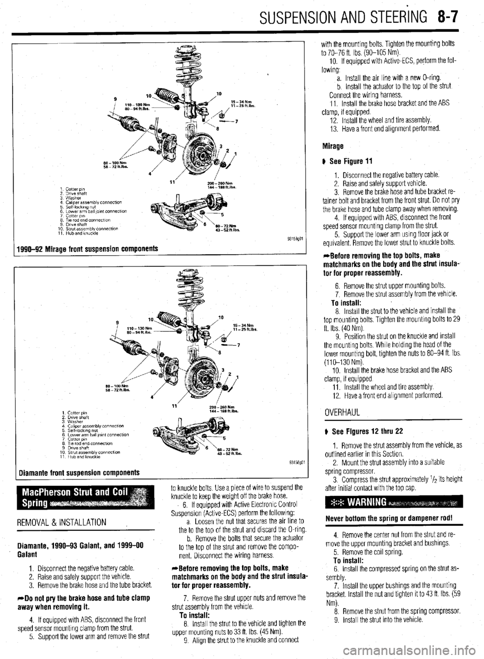
SUSPENSION AND STEERING 8-7
1 Cotter p,n
2 Drive shaft
3 Washer
4 Caliper assembly connecf~on
5 Self-IockIng ““f
6 Lower arm ball ,Ol”f Connectlo”
7 cotter PI”
8 T,e rod end connectton
9 Drive Shaft
10 Strut assembly connection
11 Hub and knuckle
1990-92 Mirage front suspension components
-
1 Cutter PI”
2 Drtve shaft
3 Washer
4 Ca,,perassembly connect~o”
5 Self-locking nut
6 Lower arm ball ,o,nt connection
7 cotter PI”
8 Tie rod end connection
9 Dwe shaft
10 Strut assembly connection
11 Hub and knuckie
Diamante front suspension components
1
to knuckle bolts Use a piece of wire to suspend the
knuckle to keep the weight off the brake hose.
6. If equipped with Active Electronrc Control
Suspension (Active-ECS) perform the followrng:
REMOVAL &INSTALLATION a. Loosen the nut that secures the an line to
the to the too of the strut and discard the O-ring.
Diamante, 1990-93 Galant, and 1999-00
Galant
1. Disconnect the negative battery cable.
2. Raise and safely support the vehicle.
3. Remove the brake hose and the tube bracket.
40 not pry the brake hose and tube clamp
awav when removino it.
b. Remove the bolts that secure the actuator
to the top of the strut and remove the compo-
nent. Disconnect the wiring harness.
*Before removing the top bolts, make
matchmarks on the body and the strut insula-
tor for proper reassembly.
7. Remove the strut upper nuts and remove the
strut assemblv from the vehicle.
4. If equipped with ABS, disconnect the front
speed sensor mounting clamp from the strut.
5. Support the lower arm and remove the strut
To instalf: 8. Install the strut to the vehicle and tighten the
upper mounting nuts to 33 ft. Ibs. (45 Nm)
9 Align the strut to the knuckle and connect with the mounting bolts. Tighten the mounting bolts
to 70-76 ft. Ibs. (90-105 Nm).
10. If equipped with Active-ECS, perform the fol-
lowing,
a. Install the air line with a new O-ring.
b Install the actuator to the top of the strut
Connect the wiring harness.
11. Install the brake hose bracket and the ABS
clamp, if equipped.
12. Install the wheel and tire assembly.
13. Have a front end alignment performed.
Mirage
# See Figure 11
1, Disconnect the negative battery cable.
2. Raise and safely support vehicle.
3. Remove the brake hose and tube bracket re-
tainer bolt and bracket from the front strut. Do not pry
the brake hose and tube clamp away when removrng.
4. If equipped with ABS, disconnect the front
speed sensor mounting clamp from the strut.
5. Support the lower arm usmg floor jack or
equivalent Remove the lower strut to knuckle bolts.
*Before removing the top bolts, make
matchmarks on the body and the strut insula-
tor for proper reassembly.
6. Remove the strut upper mounting bolts.
7. Remove the strut assembly from the vehicle.
To install: 8. Install the strut to the vehicle and install the
top mounting bolts, Tighten the mountrng bolts to 29
ft. Ibs. (40 Nm)
9. Position the strut on the knuckle and mstall
the mounting bolts, While holdrng the head of the
lower mounting bolt, tighten the nuts to 80-94 ft. Ibs.
(110-130 Nm).
10. Install the brake hose bracket and the ABS
clamp, if equipped
11 Install the wheel and tire assembly
12. Have a front end alignment performed.
OVERHAUL
) See Figures 12 thru 22
1. Remove the strut assembly from the vehicle, as
outlined earlier in this Section.
2. Mount the strut assembly into a suitable
spring compressor.
3. Compress the strut approximately r/a its height
after initial contact with the top cap.
Never bottom the spring or dampener rod!
4. Remove the center nut from the strut and re-
move the upper mounting bracket and bushings.
5. Remove the coil spring.
To install: 6. Install the compressed spring on the strut as-
sembly.
7. Install the upper bushings and the mounting
bracket Install the nut and tighten it to 43 ft. Ibs. (59
Nm).
8. Remove the strut from the spring compressor.
9. Install the strut into the vehrcle