1900 MITSUBISHI DIAMANTE height
[x] Cancel search: heightPage 308 of 408
SUSPENSION AND STEERING 8-13
W-118 Nm*
71-W ft.lbs: 83Nm
69-78 Nm
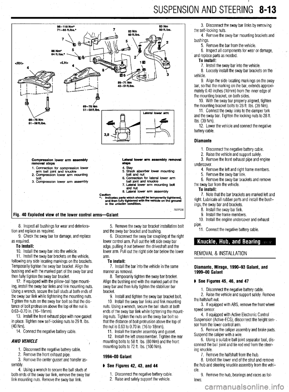
Compression lower arm assembly
removal steps
1. Connection for compression lower
arm ball joint and knuckle
2. Comoression lower arm mouniina Lateral lower tmn assembly removal
steps
4. stay
bon ’ 3. Compression lower arm assembly 6. CMlnection for lateral lower arm
ball joint and knuckle
7. lateral lower arm mounting boll
andnllt
0. hleral lower am7 assembly
CWtlOtl
l : Indicates parts which should be temporarily tightened,
and then fully tightened with the vehicle on the ground
in the unladen condition
7923PGB8 Fig. 40 Exploded view of the lower control arms-Galant
tion and replace as required. 8.
9. Inspect all bushings for wear and deteriora-
Check the sway bar for damage, and replace
as required.
To install: 10. Install the sway bar into the vehicle.
11. Install the sway bar brackets on the vehicle,
following any side locating markings on the brackets.
Temporarily tighten the sway bar bracket. Align the
bushing end with the marked part of the sway bar and
then fully tighten the sway bar bracket.
12. If equipped with the pillow-ball type mount-
ing, install the sway bar links and link mounting nuts.
Using a wrench, secure the ball studs at both ends of
the sway bar link while tightening the mounting nuts.
Tighten the nuts on the sway bar bolt so that the dis-
tance of bolt protrusion above the top of the nut is
0.63-0.70 in. (1&18mm).
13. Install the front exhaust pipe with new gasket
in place. Tighten new self-locking nuts to 29 ft. Ibs.
(40 Nm). and the sway bar bracket and bushing.
6. 5. Remove the sway bar bracket installation bolt
Disconnect the sway bar coupling at the right
lower control arm. Pull out the left side sway bar
edge, pulling it out between the driveshaft and the
lower arm. Pull out the right side bar below the lower
arm.
To install:
14. Connect the negative battery cable.
A WD VEHICLE
I
1. Disconnect the negative battery cable.
2. Remove the front exhaust pipe.
3. Remove the center gusset and transfer as-
sembly.
4. Using a wrench to secure the ball studs at
both ends of the sway bar link, remove the sway bar
link mounting nuts. Remove the sway bar link. 11. Connect the negative battery cable.
REMOVAL & INSTALLATION
7. Install the bar into the vehicle in the same Diamante, Mirage, 1996-93 Galant, and manner as removal. 1999-00 Galant 8. Temporarily tighten the sway bar bracket.
Align the bushing end with the marked part of the
sway bar and then fully tighten the stabilizer bar
bracket.
9. Install and tighten the sway bar bracket bolt.
10. Install the sway bar links and link mounting
nuts Using a wrench, secure the ball studs at both
ends of the sway bar link while tightening the mount-
ing nuts. Tighten the nuts on the sway bar bolt so
that the distance of bolt protrusion above the top of
the nut is 0.63 to 0.70 in. (16 to 18mm).
11. Install the transfer assembly and gusset.
12. Install the left crossmember. Tighten the rear
mounting bolts to 58 ft Ibs. (80 Nm) and the front
mounting bolts to 72 ft. Ibs. (100 Nm). ) See Figures 45, 46, and 47
1. Disconnect the negative battery cable.
2. Raise the vehicle and support safely. Remove
the halfshaft nut.
3. If equipped with ABS, remove the front wheel
speed sensor
1994-90 Galant
4. If equipped with Active Electronic Control
Suspension (Active-ECS), disconnect the height sen-.
sor from the lower control arm.
5. Remove the caliper assembly and brake pads.
Suspend the caliper with a wire
6. Using a suitable ball joint separator tool, dis-
connect the ball joint and tie rod end from the steer-
ing knuckle.
7. Remove the halfshaft from the hub.
8. Unbolt the lower end of the strut and remove
the hub and steering knuckle assembly from the vehi-
cle.
9 Remove the hub, bearings and races as fol-
lows.
# See Figures 42, 43, and 44
1. Disconnect the negative battery cable.
2. Raise and safely support the vehicle 3. Disconnect the sway bar links by removing
the self-locking nuts.
4. Remove the sway bar mounting brackets and
bushings.
5. Remove the bar from the vehicle.
6. Inspect all components for wear or damage,
and replace parts as needed.
To install: 7. Install the sway bar into the vehicle.
8. Loosely install the sway bar brackets on the
vehicle.
9. Align the side locating markings on the sway
bar, so that the marking on ihe bar, extends approxi-
mately 0.40 inches (1Omm) from the Inner edge of
the mounting bracket, on both sides.
10. With the sway bar properly aligned, tighten
the mounting bracket bolts to 28 ft. Ibs. (39 Nm).
11. Connect the sway links to the damper fork
and the sway bar. Tighten the locking nuts to 28 ft.
Ibs (39 Nm).
12. Lower the vehicle and connect the negative
battery cable.
Diamante
1. Disconnect the negative battery cable.
2. Raise the vehicle and support safely.
3. Remove the front exhaust pipe and engine
undercover.
4. Remove the left and right frame members.
5. Remove the sway bar link.
6. Remove the sway bar brackets and remove
the sway bar from the vehicle.
To install: 7. Note that the bar brackets are marked left and
right. Lubricate all rubber parts and install the bush-
ings, the sway bar and brackets.
8. Install the sway bar link.
9. Install the frame members.
10. Install the engine undercover and exhaust
pipe.
Page 310 of 408
SUSPENSION AND STEERING 845
144-188 ft. Ibs. (200-260 Nm). Rotate the hub ing knuckle and install a new nut. Tighten to 52 ft. 3. Remove the cotter pin, halfshaft nut and
to seat the bearing.
Ibs. (72 Nm). washer.
e. Mount the knuckle assembly in a vise.
12. Install the halfshaft into the hub/knuckle as- 4. If equipped with ABS, remove the Vehicle
Check the hub assembly turning torque and end- sembly.
Speed Sensor (VSS).
play as follows: 13. Install the two front strut lower mounting bolts
5. Remove the caliper and brake pads. Support
l Using a torque wrench and socket
and tighten to 80-94 ft. Ibs. (110-130 Nm) on Mirage
the caliper out of the way using wire.
MB990998 or equivalent, turn the hub in the or 65-76 ft. Ibs. (90-105 Nm) on Diamante models. 6. Remove the brake rotor from the hub assembly.
knuckle assembly. Note the reading on the torque
14. Install the tie rod end and tighten the nut to 7. Disconnect the upper ball joint from the
wrench and compare to the desired reading of 16
25 ft. lbs. (34 Nm) for Mirage and 21 ft. Ibs. (29 Nm) steering knuckle and pull the knuckle outward.
inch Ibs. (1.8 Nm) or less. This is known as the ‘on Diamante models
8. From the back of the knuckle, remove the
breakaway torque.
15. Install the brake disc and caliper assembly. ‘four bolts securing the hub to the knuckle.
l Check for roughness when turning the
16. If equipped with Active-ECS, connect the
9. Remove the hub and bearing assembly from
bearing.
height sensor and tighten the mounting bolt to 15 ft.
the knuckle.
0 Mount a dial indicator on the hub so the
Ibs. (20 Nm).
pointer contacts the machined surface on the hub.
17. Install the front speed sensor, if removed.
*The hub assembly is not serviceable and
l Check the end-play.
18. Install the washer and new locknut to the end should not be disassembled.
l Compare the reading to the limit of 0.002
in. (0.05mm). of the halfshaft. Tighten the locknut snugly to To install: 144-188 ft. Ibs. (200-260 Nm).
f. If the starting torque or the hub end-play
19. Install the tire and wheel assembly onto the 10. Install the hub to the steering knuckle and
are not within specifications while the nut is tighten the mounting bolts to 65 ft. Ibs. (88 Nm).
vehicle.
11.
tightened to 144-188 ft. Ibs. (200-260 Nm), the
Lower the vehicle to the ground. Connect the upper ball joint to the steering
20.
bearing, hub or knuckle have probably not been ‘knuckle and tighten the self-locking nut to 21 ft. Ibs.
(28 Nm).
installed correctly. Repeat the disassembly and 1994-98 Galant 12.
‘assembly procedure and recheck starting torque Install the axle washer and nut. Tighten the
and end-play. nut to 145-188 ft. Ibs. (200-260 Nm).
+ See Figures 48 thru 58 13. Position the rotor on the hub.
11. Install the hub and knuckle assembly onto the
vehicle. Install the lower ball joint stud into the steer- 1. Raise the vehicle and support safely. 14. Install the caliper holder and the brake
2. Remove the appropriate wheel assembly. ” caliper.
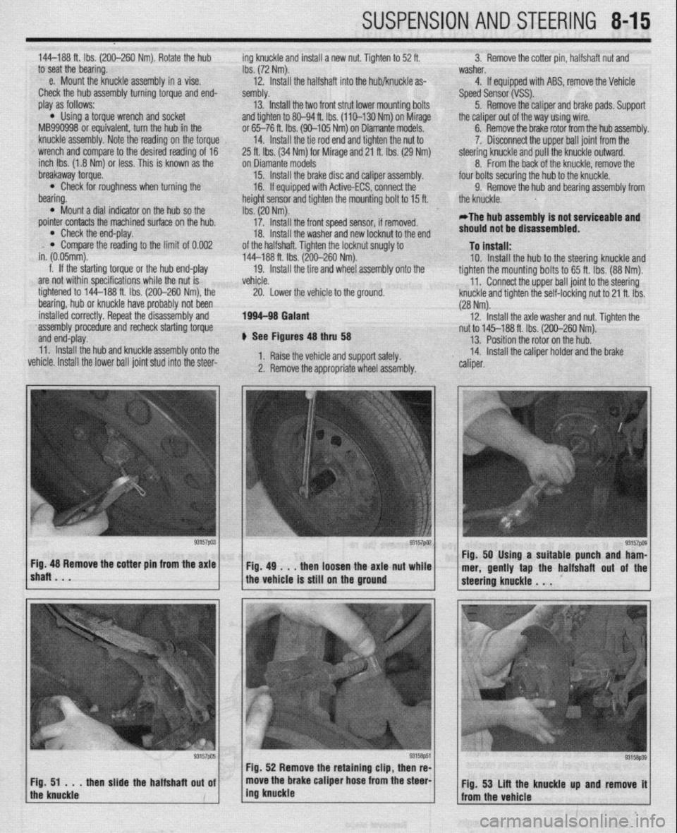
lshaRBmV * “57pa3~ ~Fig.4g~..thenloosehtheaxlattut~~;.~ Fig. 48 Remove the cotter pm from the axle Fig. 50 Using a suitable punch and ham-
mer, gently tap the halfshaft out of the
the vehicle is still on the ground
Page 319 of 408
8-24 SUSPENSION AND STEERING
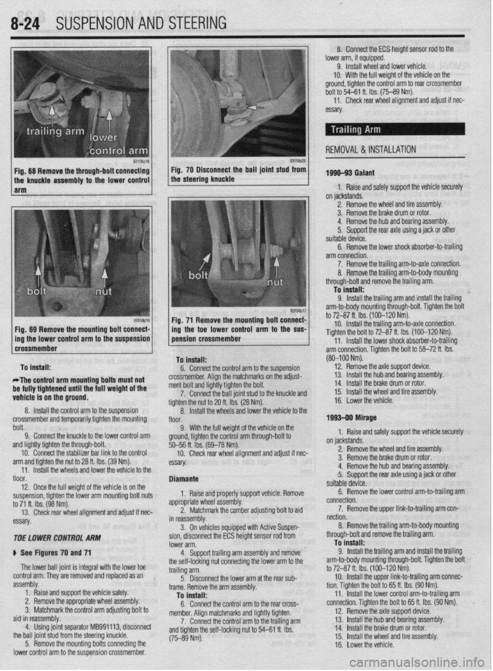
9315t$M 93158p26 Fig. 68 Remove the through-bolt connecting Fig. 70 Disconnect the ball joint stud from
the knuckle assembly to the lower control the steering knuckle
1 arm
Fig. 71 Remove the mounting bolt connect-
Fig, 89 Remove the mounting bolt connect- /
1 ing the toe lower control arm to the SW
Dolt. 9; Connect the knuckle to the lower control arm 9. With the full weigh
ground, tighten the control
and lightly tighten the through-bolt.
10. Connect the stabilizer bar link to the control
arm and tighten the nut to 28 ft. Ibs. (39 Nm).
11. Install the wheels and lower the vehicle to the
floor.
12. Once the full weight of the vehicle is on the
suspension, tighten the lower arm mounting bolt nuts
to 71 ft. Ibs. (98 Nm).
13. Check rear wheel alignment and adjust if nec-
essary.
TOE LOWER CONTROL ARhl
ti See Figures 70 and 71
The lower ball joint is integral with the lower toe
control arm. They are removed and replaced as an
assembly.
1. Raise and support the vehicle safely.
2. Remove the appropriate wheel assembly.
3. Matchmark the control arm adjusting bolt to
aid in reassembly.
4. Using joint separator MB991113, disconnect
the ball joint stud from the steering knuckle.
5. Remove the mounting bolts connecting the
lower control arm to the suspension crossmember. %--56 ft. ibs. (
10. Check
essay. rem an0 aajusr
II nec-
orl vehicle Remove
ldiustina bolt to aid
soen- Diamante
1, Raise and properly supp
appropriate whl
eel assembly.
2. Matchn
narkthe camber a , _
in reassembly.
3. On vehicles equipped with Active Su r
sion, disconnect the ECS height sensor rod from
lower arm.
4. Support trailing arm assembly and remove
the self-locking nut connecting the lower arm to the
trailing arm.
5. Disconnect the lower arm at the rear sub-
frame. Remove the arm assembly.
To install:
6. Connect the control arm to the rear cross-
member. Alion matchmarks and liahtlv tiohten.
7. Connect the control arm tothe trailing arm
and tighten the self-locking nut to 54-P e rho I I IL IY.J.
(75-89 Nm). 8. Connect the ECS height sensor rod to the
lower arm, if equipped.
9. Install wheel and lower vehicle.
IO. With the full weight of the vehicle on the
ground, tighten the control arm to rear crossmember
bolt to 54-61 ft. Ibs. (75-89 Nm).
11,
Check rear wheel alignment and adjust if nec-
essary
1996-93 Galant
1, Raise and safely support the vehicle securely
on jackstands.
2. Remove the wheel and tire assembly.
3. Remove the brake drum or rotor.
4. Remove the hub and bearing assembly.
5.
Support the rear axle using a jack or other
suitable device.
6. Remove the lower shock absorber-to-trailing
arm connection.
7. Remove the trailing arm-to-axle connection.
REMOVAL & INSTALLATION
(80-100 Nm).
12.
Remove the axle suooort device.
on jackstands.
2. Remove the wheel and tire assembly.
3. Remove the brake drum or rotor.
4. Remove the hub and bearing assembly.
5.
Support the rear axle using a jack or other
suitable device.
6. Remove the lower control arm-to-trailing arm
connection.
7. Remove the upper link-to-trailing arm con-
nection.
8. Remove the trailing arm-to-body mounting
through-bolt and remove the trailing arm.
To install:
9.
Install the trailing arm and install the trailing
arm-to-body mounting through-bolt. Tighten the bolt
to 72-87 ft. Ibs. (100-120 Nm).
10. Install the upper link-to-trailing arm connec-
tion. Tighten the bolt to 65 ft. Ibs. (90 Nm).
11. Install the lower control arm-to-trailing arm
connection. Tighten the bolt to 65 ft. Ibs. (90 Nm).
12. Remove the axle support device.
13. Install 1 he hub and bearing assembly.
14 Install 1
. _ .he brake drum or rotor.
15.
Install the wheel and tire assembly.
16. Lower the vehicle.
Page 340 of 408
9-4 BRAKES
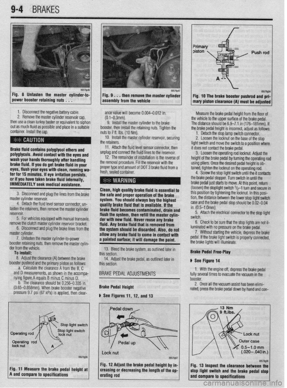
Fig 8 Unfasten the master cylinder-to-
power booster retaining nuts . . . F57g’6~ Fig. 9 . . . then remove the master cylinder
assembly from the vehicle Fig. 10 The brake booster pushrod and prf-
mary piston clearance (A) must be adjusted
1. Disconnect the negative battery cable.
2. Remove the master cylinder reservoir cap,
then use a clean turkey baster or equivalent to siphon
out as much fluid as possible and place in a suitable
container. Install the cap.
Brake fluid contains polyglycol ethers and
polyglycols. Avoid contact with the eyes and
wash your hands thoroughly after handling
brake fluid. If you do get brake fluid in your
eyes, flush your eyes with clean, running wa-
ter for 15 minutes. If eye irritation persists,
or if you have taken brake fluid internally,
IMMEDIATELY seek medical assistance.
3. Disconnect and plug the lines from the brake
master cylinder reservoir.
4. Detach the fluid level sensor connector, un-
fasten the retainers, then remove the master cylinder
reservoir.
5. For vehicles equipped with manual transaxle,
remove the clutch master cylinder reservoir bracket.
6. Disconnect and plug the brake lines from the
master cylinder.
7. Unfasten the master cylinder-to-power
booster retainino nuts, then remove the master cvlin- ante value will become 0.004-0.012 in.
(0.1-0.3mm).
9. install the master cylinder to the brake
booster, then install the retaining nuts. Tighten the
nuts to 7 ft. Ibs. (10 Nm).
10. Install the master cylinder reservoir, securing
the retainers.
11. Attach the fluid level sensor connector, then
unplug and connect the fluid lines to the reservoir.
12. The remainder of installation is the reverse of
the removal procedure. Fill the reservoir with the
proper type and amount of DOT 3 brake fluid from a
fresh, sealed container.
I l
Clean, high quality brake fluid is essential to
the safe and proper operation of the brake
system. You should always buy the highest
quality brake fluid that is available. If the
brake fluid becomes contaminated, drain and
flush the system, then refill the master cylin-
der with new fluid. Never reuse any brake
fluid. Any brake fluid that is removed from
the system should be discarded. Also, do not
allow any brake fluid to come in contact with
a painted surface; it will damage the paint. Measure the brake pedal height from the floor of
the vehicle to the upper surface of the brake pedal.
The distance should be 6.9-7.1 in (176181mm). If
the brake pedal height is incorrect, adjust as follows:
1. Detach the stop lamp switch connector.
2. Loosen the locknut on the base of the stop
light switch and move the switch to a position where
it does not contact the brake pedal.
3. Loosen the operating rod locknut. Adjust the
height of the brake pedal by turning the operating rod
using pliers. Once the desired pedal height is ob-
tained, tighten the locknut on the operating rod.
4. Screw the stop light switch until the it contacts
the brake pedal stopper. Turn switch in until the
brake pedal just starts to move. At this point, return
(loosen) the stoplight switch $-1 turn and secure in
this position by tightening the locknut. In this posi-
tion, the distance between the lower stop light switch
case and the brake pedal stop should be 0.02-0.04
in. (0.5-l .Omm).
5. Attach the electrical connector to the stop light
switch.
6. Check to be sure that the stop lights are not il-
luminated with no pressure on the brake pedal.
7. Without starting the vehicle, depress the brake
pedal. If the brake light switch is properly connected,
the brake lights will illuminate.
der from the vefiicle.
To install:
8. Adjust the clearance (A)
booster pushrod ant
a. Calculate tl -,
between the brake
I the primary piston as follows:
le clearance A from the B, C
accompa-
i D.
I.335 in.
negative and D measurements, as shown in the
nying figure.A equals B minus C minus
b. The clearance should be 0.256-t
(0.65-0.858mm). When brake booster I
pressure 9.7 psi (67 kPa) is applied, then clear- 13. Bleed the brake system, as outlined later in
this section.
14. Adjust the brake pedal, as outlined later in
this section.
BRAKE PEDAL ADJUSTMENTS
Brake Pedal Height
b See Figures 11, 12, and 13 Brake Pedal Free-Play
II See Figure 14
1. With the engine off, depress the brake pedal
fully several times to evacuate the vacuum in the
booster.
2. Once all the vacuum assist has been elimi-
nated, press the brake pedal down by hand and con-
/
0.5-1.0 mm (.020-B40in.J I
I
I I
Fig. 12 Adjust the brake pedal height by in- I I.
@57w
Cir 44 “a*., .._^ *I.- 9.--l,- ---I-* L-@-L. -I Fig. 13 Inspect the clearance between thf . . - _-.L -*.a- - . . * _ . . . . ._ . rly. I I rnca~urc we urime peoai nefgnr ar
A and compare to specifications creasmg or aecreasing the lengrn or me op-
erating rod mop llgnt WItCh arm the brake pedal stop
and compare to specifications
Page 371 of 408
BODYANDTRIM 10-3
3. Check the hood latch operation; it should en-
gage easily and smoothly. The latch should release
without the use of excessive force. The hood latch
mounting bolts may be loosened; the latch can be
adjusted left/right or up/down to compensate for the
hood striker position.
4. With the hood closed and latched, check the
height of the hood. It should sit even with the fender
tops; this dimension may be adjusted by turning the
hood stops to a higher or lower position. Note that
adjusting these stops may require readjustment of the
latch to position the hood correctly.
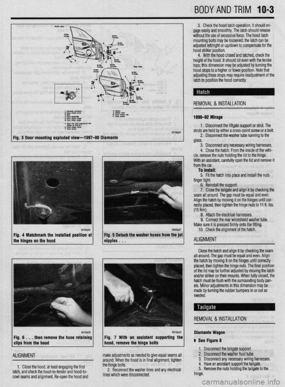
REMOVAL &INSTALLATION
1999-92 Mirage
1. Disconnect the liftgate support or strut. The
9315Ql10 struts are held by either a cross-point screw or a bolt.
2. Disconnect the washer tube running to the
glass.
3. Disconnect any necessary wiring harnesses.
4. Close the hatch. From the inside of the vehi-
cle, remove the nuts holding the lid to the hinge.
With an assistant. carefullv ooen the lid and remove it
from the car. ’
To install:
5. Fit the hatch into place and install the nuts
finger tight.
6. Reinstall the support.
7. Close the tailgate and align it by checking the
seam all around. Thegap must be equal and even.
Align the hatch by moving it on the hinges until cor-
rectly placed, then tighten the hinge nuts to 11 ft. Ibs.
(15 Nm).
8. Attach the electrical harnesses.
9. Connect the rear windshield washer tube.
Make sure it is pressed firmly onto the fitting.
10. Check the alignment of the hatch.
ALIGNMENT
Close the hatch and align it by checking the seam
all around. The gap must be equal and even. Align
the hatch by moving it on the hinges until correctly
placed, then tighten the hinge nuts. The final position
of the lid may be further adjusted by moving the latch
and/or striker on their mounts. When fully closed, the
hatch must be flush with the surrounding body pan-
els. Minor adjustments in this dimension may be
made by turning the rubber bumpers in or out as
needed.
REMOVAL &INSTALLATION
then remove the hose retaining
ALIGNMENT
1, Close the hood, at least engaging the first
latch, and check the hood-to-fender and hood-to-
cowl seams and alignment. Re-open the hood and Fig. 7 With an assistant supporting the
make adjustments as needed to give equal seams all
around. When the hood is in final alignment, tighten
the hinge bolts.
2. Reconnect the washer lines and any electrical
lines which were disconnected. Diamante Wagon
ti See Figure 8
1. Disconnect the tailgate support.
2. Disconnect the washer fluid tube.
3. Disconnect any necessary wiring harnesses.
4. Have an assistant support the tailgate.
5. Remove the nuts holding the tailgate to the
hinge.
Page 372 of 408
10-4 BODYANDTRIM
Fig. 8 Tailgate assembly mounting-Dia-
mante Wagon
6. Remove the tailgate from the vehicle and place
it in a safe place.
7. The installation is the reverse of removal.
Tighten the hinge
nuts to IO ft. Ibs. (14 Nm).
8. Check the alignment of the tailgate.
ALIGNMENT
To adjust the tailgate, loosen the tailgate hinge-to-
body bolts or tailgate latch assembly mounting
screws and adjust as necessary.
REMOVAL &INSTALLATION
1. Disconnect the negative battery cable.
2. Open the trunk lid. Identify the trunk release
cable running from the latch to the body.
3. Disconnect the cable from the latch.
4. Detach any necessary electrical connectors.
5. Outline the position of the hinges on the
trunk lid.
6. Support the trunk lid in the open position.
7. If equipped, insert a small prytool into the
lock cover slit, remove the lock covers, then remove
the trunk lid gas springs.
8. Unfasten the retaining bolts, then remove the
trunk lid hinges.
9. Remove the trunk lid from the vehicle
10. Installation is the reverse of the removal pro-
cedure.
11. If necessary, align the trunk lid.
ALIGNMENT
1. Close the lid and check both the seam width
all around and the closed height. The trunk lid must
be flush with the adjacent panels. Minor height ad-
justments may be made by turning the rubber
bumpers on the trunk lid. Additional adjustments re-
quire loosening and repositioning of the latch and/or
striker.
REMOVAL &INSTALLATION
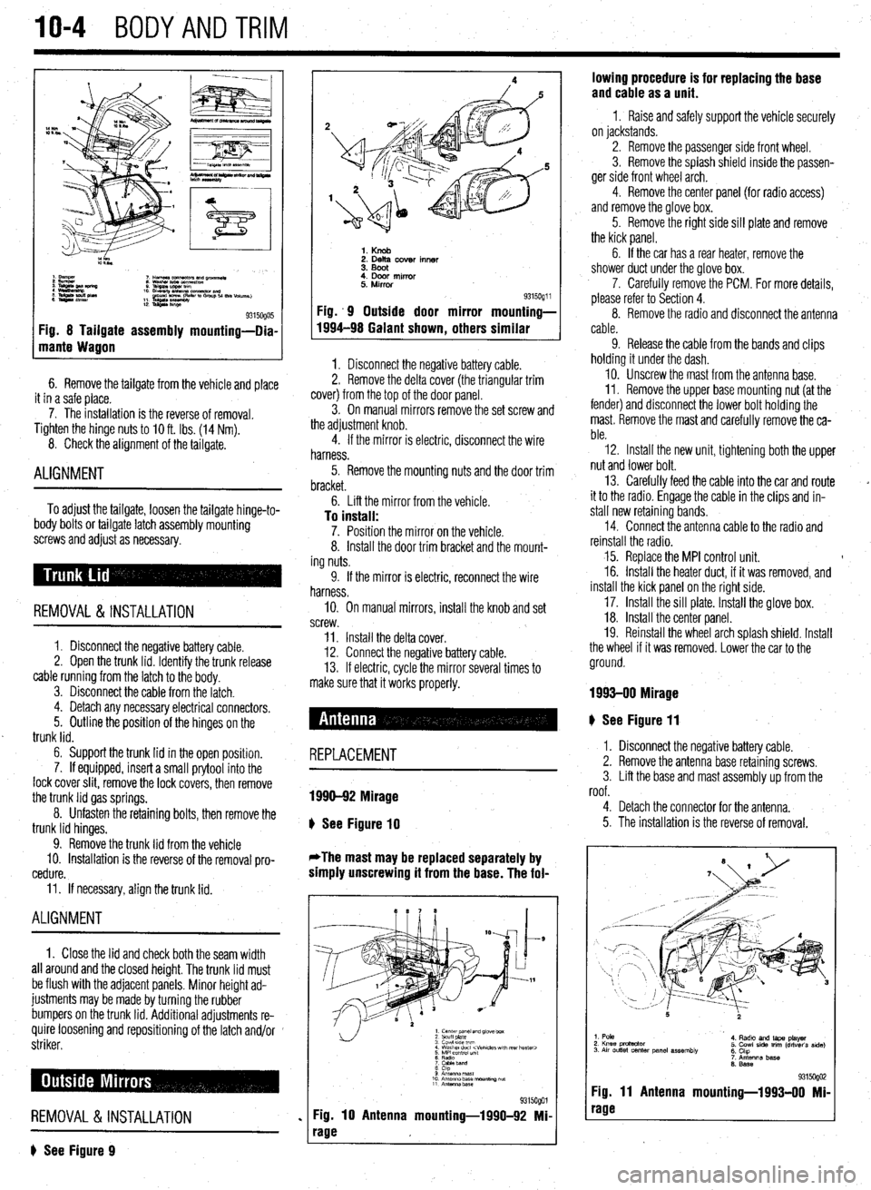
? See Figure 9
1. Knob 2. Delta cover inner
3. Boot
4. Door mirror
5. Mirror
Fig. .9 Outside door mirror
1994-98 Galant shown
, others 9315oQ1 i mounting-
similar
1. Disconnect the negative battery cable.
2. Remove the delta cover (the triangular trim
cover) from the top of the door panel.
3. On manual mirrors remove the set screw and
the adjustment knob.
4. If the mirror is electric, disconnect the wire
harness.
5. Remove the mounting nuts and the door trim
bracket.
6. Lift the mirror from the vehicle.
To install: 7. Position the mirror on the vehicle.
8. Install the door trim bracket and the mount-
ing nuts.
9. If the mirror is electric, reconnect the wire
harness.
IO. On manual mirrors, install the knob and set
screw.
11. Install the delta cover.
12. Connect the negative battery cable.
13. If electric, cycle the mirror several times to
make sure that it works properly.
# See Figure 11
REPLACEMENT
1990-92 Mirage
b
See Figure 10
*The mast may be replaced separately by
simply unscrewing it from the base. The fol-
1. center panel and glove box
2 scuff plate
3 cowl 51ae wm
4 Washer duct
7 CaMeband
8 cap
9 Anrsnna mast
10 Antenna base “ourmng ““f
11 Antennz.base
%i%Qol
Fig. 10 Antenna mounting-1990-92 Mi-
rage lowing procedure is for replacing the base
and cable as a unit.
1 I Raise and safely support the vehicle securely
on jackstands.
2. Remove the passenger side front wheel.
3. Remove the splash shield inside the passen-
ger side front wheel arch.
4. Remove the center panel {for radio access)
and remove the glove box.
5. Remove the right side sill plate and remove
the kick panel.
6. If the car has a rear heater, remove the
shower duct under the glove box.
7. Carefully remove the PCM. For more details,
please refer to Section 4.
8. Remove the radio and disconnect the antenna
cable.
9. Release the cable from the bands and clips
holding it under the dash.
10. Unscrew the mast from the antenna base.
II. Remove the upper base mounting nut (at the
fender) and disconnect the lower bolt holding the
mast. Remove the mast and carefully remove the ca-
ble.
12. Install the new unit, tightening both the upper
nut and lower bolt.
13. Carefully feed the cable into the car and route
it to the radio. Engage the cable in the clips and in-
stall new retaining bands.
14. Connect the antenna cable to the radio and
reinstall the radio.
15. Replace the MPI control unit. t
16. Install the heater duct, if it was removed, and
install the kick panel on the right side.
17. Install the sill plate. Install the glove box.
18. Install the center panel.
19. Reinstall the wheel arch splash shield. Install
the wheel if it was removed. Lower the car to the
ground.
1993-00 Mirage
I. Disconnect the negative battery cable.
2. Remove the antenna base retaining screws.
3. Lift the base and mast assembly up from the
roof.
4. Detach the connector for the antenna.
5. The installation is the reverse of removal.
1. Pole
2. Knee protactor
3. Air outlet center panel assembly 4. Radto and laps player
5. Cowl side trim (driver’s side)
6. Chp
7. Antenna base
6. Base
931 !iogo2 Fig. 11 Antenna mounting-1993-00 Mi-
rage
Page 392 of 408
II-10 TROUBLESHOOTING
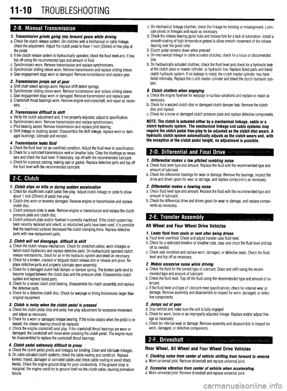
1. Transmission grinds going into forward gears while driving
a. Check the clutch release system. On clutches with a mechanical or cable linkage,
check the adjustment. Adjust the clutch pedal to have 1 inch (25mm) of free-play at
the pedal.
b. If the clutch release system is hydraulically operated, check the fluid level and, if low,
top off using the recommended type and amount of fluid. ,
c. Synchronizers worn. Remove transmission and replace synchronizers.
d. Synchronizer sliding sleeve worn. Remove transmission and replace sliding sleeve.
e. Gear engagement dogs worn or damaged. Remove transmission and replace gear.
2. Transmission jumps out of gear
a. Shift shaft detent springs worn. Replace shift detent springs.
b. Synchronizer sliding sleeve worn. Remove transmission and replace sliding sleeve.
c. Gear engagement dogs worn or damaged. Remove transmission and replace gear.
d. Crankshaft thrust bearings worn. Remove engine and crankshaft, and repair as neces-
sary.
3. Transmission difficult to shift
a. Verify the clutch adjustment and, if not properly adjusted, adjust to specification.
b. Synchronizers worn. Remove transmission and replace synchronizers.
c. Pilot bearing seized. Remove transmission and replace pilot bearing.
d. Shift linkage or bushing seized. Disassemble the shift linkage, replace worn or dam-
aged bushings, lubricate and reinstall.
4. Transmission leaks fluid
a. Check the fluid level for an overfilled condition. Adjust the fluid level to specification.
b. Check for a restricted transmission vent or breather tube. Clear the blockage as neces-
sary and check the fluid level. If necessary, top off with the recommended lubricant.
c. Check for a porous casting, leaking seal or gasket. Replace defective parts and top off
the fluid level with the recommended lubricant.
1. Clutch slips on hills or during sudden acceleration
a. Check for insufficient clutch pedal free-play. Adjust clutch linkage or cable to allow
about 1 inch (25mm) of pedal free-play.
b. Clutch disc worn or severely damaged. Remove engine or transmission and replace
clutch disc.
c. Clutch pressure plate is weak. Remove engine or transmission and replace the clutch
pressure plate and clutch disc.
d. Clutch pressure plate and/or flywheel incorrectly machined. If the clutch system has
been recently replaced and rebuilt, or refurbished parts have been used, it is possible
that the machined surfaces decreased the clutch clamping force. Replace defective
parts with new replacement parts.
2. Clutch will not disengage, difficult to shift
a. Check the clutch release mechanism. Check for stretched cables, worn linkages or
failed clutch hydraulics and replace defective parts. On hydraulically operated clutch
release mechanisms, check for air in the hydraulic system and bleed as necessary.
b. Check for a broken, cracked or fatigued clutch release arm or release arm pivot. Re-
place defective parts and properly lubricate upon assembly.
c. Check for a damaged clutch hub damper or damper spring. The broken parts tend to
become lodged between the clutch disc and the pressure plate. Disassemble clutch
system and replace failed parts.
d. Check for a seized clutch pilot bearing. Disassemble the clutch assembly and replace
the defective parts.
e. Check for a defective clutch disc. Check for warpage or liningthicknesses larger than
original equipment.
3. Clutch is noisy when the clutch pedal is pressed
a. Check the clutch pedal stop and pedal free-play adjustment for excessive movement
and adjust as necessary.
b. Check for a worn or damaged release bearing. If the noise ceases when the pedal is re-
leased, the release bearing should be replaced.
c. Check the engine crankshaft axial play. If the crankshaft thrust bearings are worn or
damaged, the crankshaft will move when pressing the clutch pedal. The engine must
be disassembled to replace the crankshaft thrust bearings.
4. Clutch pedal extremely difficult to press
a. Check the clutch pedal pivots and linkages for binding. Clean and lubricate linkages.
b. On cable actuated clutch systems, check the cable routing and condition. Replace
kinked, frayed, damaged or corroded cables and check cable routing to avoid sharp
bends. Check the engine ground strap for poor conductivity. If the ground strap is
marginal, the engine could try to ground itself via the clutch cable, causing premature
failure. c. On mechanical linkage clutches, check the linkage for binding or misalignment. Lubri-
cate pivots or linkages and repair as necessary.
d. Check the release bearing guide tube and release fork for a lack of lubrication. Install a
smooth coating of high temperature grease to allow smooth movement of the release
bearing over the guide tube.
5. Clutch pedal remains down when pressed
a, On mechanical linkage or cable actuated clutches, check for a loose or disconnected
link.
b. On hydraulically actuated clutches, check the fluid level and check for a hydraulic leak
at the clutch slave or master cylinder, or hydraulic line. Replace failed parts and bleed
clutch hydraulic system. If no leakage is noted, the clutch master cylinder may have
failed internally. Replace the clutch master cylinder and bleed the clutch hydraulic sys-
tem.
6. clutch chatters when engaging
a. Check the engine flywheel for warpage or surface variations and replace or repair as
necessary.
b. Check for a warped clutch disc or damaged clutch damper hub. Remove the clutch
disc and replace.
c. Check for a loose or damaged clutch pressure plate and replace defective components.
NOTE: The clutch is actuated either by a mechanical linkage, cable or a
clutch hydraulic system. The mechanical linkage and cable systems may
require the clutch pedal free-play to be adjusted as the clutch disc wears. A
hydraulic clutch system automatically adjusts as the clutch wears and, with
the exception of the clutch pedal height, no adjustment is possible.
1. Differential makes a low pitched rumbling noise
a. Check fluid level type and amount. Replace the fluid with the recommended type and
amount of lubricant.
b. Check the differential bearings for wear or damage. Remove the bearings, inspect the
drive and driven gears for wear or damage, and replace components as necessary.
2. Differential makes a howling noise
a. Check fluid level type and amount. Replace the fluid with the recommended type and
amount of lubricant.
b. Check the differential drive and driven gears for wear or damage, and replace compo-
nents as necessary.
All Wheel and Four Wheel Drive Vehicles
1. Leaks fluid from seals or vent after being driven
a. Fluid level overfilled. Check and adjust transfer case fluid level.
b. Check for a restricted breather or breather tube, clear and check the fluid level and top
off as needed.
c. Check seal condition and replace worn, damaged, or defective seals. Check the fluid
level and top off as necessary.
2. Makes excessive noise while driving
a. Check the fluid for the correct type of lubricant. Drain and refill using the recom-
mended type and amount of lubricant.
b. Check the fluid level. Top off the fluid using the recommended type and amount of lu-
bricant.
c. If the fluid level and type of lubricant meet specifications, check for internal wear or
damage. Remove assembly and disassemble to inspect for worn, damaged, or defec-
tive components.
3. Jumps out of gear
a. Stop vehicle and make sure the unit is fully engaged.
b. Check for worn, loose or an improperly adjusted linkage. Replace and/or adjust link-
age as necessary.
c. Check for internal wear or damage. Remove assembly and disassemble to inspect for
worn, damaged, or defective components.
Rear Wheel, All Wheel and Four Wheel Drive Vehicles
1. Clunking noise from center of Vehicle shifting from forward to reverse
a. Worn universal joint. Remove driveshaft and replace universal joint.
2. Excessive vibration from center of vehicle when accelerating
a. Worn universal joint. Remove driveshaft and replace universal joint.