1900 MITSUBISHI DIAMANTE brakes
[x] Cancel search: brakesPage 2 of 408
.
1-2 GENERALINFORMATIONAND MAINTENANCE
Chitton’s Total Car Care manual for the 199M10
Mitsubishi Mirage, Galant and Diamante is intended
to help you learn more about the inner workings of
your vehicle while saving you money on its upkeep
and operation.
The beginning of the book will likely be referred to
the most, since that is where you will find information
for maintenance and tune-up. The other sections deal
with the more complex systems of your vehicle. Oper-
ating systems from engine through brakes are cov-
ered to the extent that the average do-it-yourselfer be-
comes mechanically involved. This book will not
explain such things as rebuilding a differential for the
simple reason that the expertise required and the in-
vestment in special tools make this task uneconomi-
cal. It will, however, give you detailed instructions to
help you change your own brake pads and shoes, re-
place spark plugs, and perform many more jobs that
can save you money, give you personal satisfaction
and help you avoid expensive problems.
A secondary purpose of this book is a reference for
owners who want to understand their vehicle and/or
their mechanics better. In this case, no tools at all are
required.
Before removing any bolts, read through the entire
procedure. This will give you the overall view of what
tools and supplies will be required. There is nothing
more frustrating than having to walk to the bus stop
on Monday morning because you were short one bolt
on Sunday afternoon. So read ahead and plan ahead.
Each operation should be approached logically and
all procedures thoroughly understood before attempt-
ing any work.
All sections contain adjustments, maintenance, re-
moval and installation procedures, and in some cases,
repair or overhaul procedures. When repair is not con-
sidered practical, we tell you how to remove the part
and then how to install the new or rebuilt replacement.
In this way, you at least save labor costs. “Backyard”
repair of some components is just not practical.
Many procedures in this book require you to “label
and disconnect. . ” a group of lines, hoses or wires.
Don’t be lulled into thinking you can remember where
everything goes-you won’t. If you hook up vacuum
or fuel lines incorrectly, the vehicle may run poorly, if
at all. If you hook up electrical wiring incorrectly, you
may instantly learn a very expensive lesson.
You don’t need to know the official or engineering
name for each hose or line. A piece of masking tape
on the hose and a piece on its fitting will allow you to
assign your own label such as the letter A or a short name. As long as you remember your own code, the
lines can be reconnected by matching similar letters
or names. Do remember that tape will dissolve in
gasolrne or other fluids; if a component is to be
washed or cleaned, use another method of identifica-
tion. A permanent felt-tipped marker or a metal scribe
can be very handy for marking metal parts. Remove
any tape or paper labels after assembly.
It’s necessary to mention the difference between
maintenance and repair Maintenance includes rou-
tine inspections, adjustments, and replacement of
parts which show signs of normal wear Maintenance
compensates for wear or deterioration. Repair implies
that something has broken or is not working. A need
for repair is often caused by lack of maintenance. Ex-
ample, draining and refilling the automatic transaxle
fluid is maintenance recommended by the manufac-
turer at specific mileage intervals. Failure to do this
can shorten the life of the transmission/transaxle, re-
quiring very expensive repairs. While no maintenance
program can prevent items from breaking or wearing
out, a general rule can be stated: MAINTENANCE IS
CHEAPER THAN REPAIR.
Two basic mechanrc’s rules should be mentioned
here. First, whenever the left side of the vehicle or en-
gine is referred to, it is meant to specify the drivers
side. Conversely, the right side of the vehicle means
the passengers side. Second, screws and bolts are
removed by turning counterclockwise, and tightened
by turning clockwrse unless specifically noted.
Safety is always the most important rule. Con-
stantly be aware of the dangers involved in working
on an automobile and take the proper precautions.
See the informatron in this section regarding SER-
VICING YOUR VEHICLE SAFELY and the SAFETY
NOTICE on the acknowledgment page.
Pay attention to the instructions provided. There
are 3 common mistakes in mechanical work:
1. Incorrect order of assembly, disassembly or
adjustment. When taking something apart or putting
it together, performing steps in the wrong order usu-
ally just costs you extra time; however, it CAN break
something. Read the entire procedure before begin-
ning disassembly. Perform everything in the order in
which the instructions say you should, even if you
can’t immedrately see a reason for it. When you’re
taking apart something that is very intricate, you
might want to draw a picture of how it looks when as-
sembled at one point in order to make sure you get everything back in its proper position. We will supply
exploded views whenever possible. When making
adjustments, perform them in the proper order. One
adjustment possibly will affect another.
2. Overtorquing (or undertorquing). While it is
more common for overtorquing to cause damage,
undertorquing may allow a fastener to vibrate loose
causing serious damage. Especially when dealing
with aluminum parts, pay attention to torque specifi-
cations and utilize a torque wrench in assembly. If a
torque figure is not available, remember that if you
are using the right tool to perform the job, you will
probably not have to strain yourself to get a fastener
tight enough. The pitch of most threads is so slight
that the tension you put on the wrench will be multi-
plied many times in actual force on what you are
tightening. A good example of how critical torque is
can be seen in the case of spark plug installation, es-
pecially where you are putting the plug into an alu-
minum cylinder head. Too little torque can fail to
crush the gasket, causing leakage of combustion
gases and consequent overheating of the plug and
engine parts. Too much torque can damage the
threads or distort the plug, changing the spark gap.
There are many commercial products available for
ensuring that fasteners won’t come loose, even if they
are not torqued just right (a very common brand is
Loctite? If you’re worried
about getting something
together tight enough to hold, but loose enough to
avoid mechanical damage during assembly, one of
these products might offer substantial insurance. Be-
fore choosing a threadlocking compound, read the
label on the package and make sure the product is
compatible with the materials, fluids, etc. involved.
3. Crossthreading. This occurs when a part such
as a bolt is screwed into a nut or casting at the wrong
angle and forced. Crossthreading is more likely to
occur if access is difficult. It helps to clean and lubri-
cate fasteners, then to start threading the bolt, spark
plug, etc. with your fingers If you encounter resis-
tance, unscrew the part and start over again at a dif-
ferent angle until it can be inserted and turned several
times without much effort. Keep in mind that many
parts, especially spark plugs, have tapered threads,
so that gentle turning will automatically bring the part
you’re threading to the proper angle. Don’t put a
wrench on the part until its been tightened a couple
of turns by hand. If you suddenly encounter resis-
tance, and the part has not seated fully, don’t force it.
Pull it back out to make sure it’s clean and threading
properly.
Be sure to take your time and be patient, and al-
ways plan ahead. Allow yourself ample time to per-
form repairs and maintenance You may find main-
taining your car a satisfying and enjoyable
experience.
b See Figures 1 thru 15
Naturally, without the proper tools and equipment
it is impossible to properly service your vehicle. It
would also be virtually impossible
to catalog every
tool that you would need to perform all of the opera-
tions in this book. Of course, It would be unwise for
the amateur to rush out and buy an expensive set of
tools on the theory that he/she may need one or more
of them at some time, The best approach is to proceed slowly, gathering savings will
be far outweighed by frustration and
a good quality set of those tools that are used most mangled knuckles.
frequently Don’t be misled by the low cost of bargain Begin accumulating those tools that are used most
tools. It is far better to spend a little more for better frequently: those associated with routine maintenance
quality. Forged wrenches, 6 or 12-point sockets and and tune-up. In addition to the normal assortment of
fine tooth ratchets are by far preferable to their less screwdrivers and pliers, you should have the follow-
expensive counterparts. As any good mechanic can ing tools:
tell you, there are few worse experiences than trying
l Wrenches/sockets and combination open
to work on a vehicle with bad tools. Your monetary end/box end wrenches in sizes from %-% in. or
Page 42 of 408
GENERALINFORMATIONAND MAINTENANCE l-43
l Special car washing detergent is the best to
use. Liquid dishwashing detergent can remove wax
and leave the car’s paint unprotected and in addition
some liquid detergents contains abrasives which can
scratch the paint.
l Bird droppings should be removed from the
paintwork as soon as possible, otherwise the finish
may be permanently stained.
When the car is driven immediately after be-
ing washed, apply the brakes several times
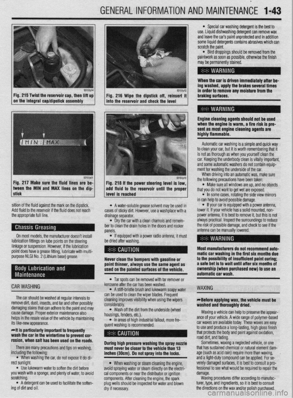
93151p14 93151p12 Fig. 215 Twist the reservoir cap, then lift up
I I
in order to remove any moisture from the
Fig. 216 Wipe the dipstick off, reinsert it braking surfaces.
on the integral cap/dipstick assembly
into the reservoir and check the level
I
Engine cleaning agents should not be used
when the engine is warm, a fire risk is pre-
sent as most engine cleaning agents are
highly flammable.
sition of the fluid against the mark on the dipstick,
Add fluid to the reservoir if the fluid does not reach
the appropriate full line.
On most models, the manufacturer doesn’t install
lubrication fittings on lube points on the steering
linkage or suspension. However, if the lubrication
point does have a grease fitting, lubricate with multi-
purpose NLGI No. 2 (Lithium base) grease.
CAR WASHING
The car should be washed at regular intervals to
remove dirt, dust, insects, and tar and other possibly
damaging stains that can adhere to the paint and may
cause damage. Proper exterior maintenance also
helps in the resale value of the vehicle by maintaining
its like-new appearance.
Mt is particularly important ta frequentiy
wash the car in the wintertime to prevent cor-
rosion, when salt has been used on the roads.
There are many precautions and tips on washing,
including the following:
l When washing the car, do not expose it do di-
rect sunlight.
. Use lukewarm water to soften the dirt before
you wash with a sponge, and plenty of water, to avoid
scratching.
l A detergent can be used to facilitate the soften-
ing of dirt and oil. * A water-soluble grease solvent may be used in
cases of sticky dirt. However, use a washplace with a
drainage separator.
l Dry the car with a clean chamois and remem-
ber to clean the drain holes in the doors and rocker
panels.
l If equipped with a power radio antenna, it must
be dried after washing.
Never clean the bumpers with gasoline or
paint thinner, always use the same agent as
used on the painted surfaces of the vehicle.
l Tar spots can be removed with tar remover or
kerosene after the car has been washed.
l A stiff-bristle brush and lukewarm soapy water
can be used to clean the wiper blades. Frequent
cleaning improves visibility when using the wipers
considerably.
l Wash off the did from the underside (wheel
housings, fenders, etc.).
l In areas of high industrial fallout, more fre-
quent washing is recommended.
During high pressure washing the spray nonle
must never be closer to the vehicle than 13
inches (30cm). Do not spray into the locks.
l When washing or steam cleaning the engine,
avoid spraying water or steam directly on the electri-
cal components or near the distributor or ignition
components. After cleaning the engine, the spark
plug wells should be inspected for water and blown
dry if necessary. Automatic car washing is a simple and quick way
to clean your car, but it is worth remembering that it
is not as thorough as when you yourself clean the
car. Keeping the underbody clean is vitally important,
and some automatic washers do not contain equip-
ment for washing the underside of the car.
When driving into an automatic was, make sure
the following precautions have been taken:
l Make sure all windows are up, and no objects
that you do not want to get wet are exposed.
l In some cases, rotating the side view mirrors
in can help to avoid possible damage.
l If your car is equipped with a power antenna,
lower it. If your vehicle has a solid mounted, non-
power antenna, it is best to remove it, but this is not
always practical. Inspect the surroundings to reduce
the risk of possible damage, and check to see if the
antenna can be manually lowered.
Most manufacturers do not recommend auto-
matic car washing in the first six months due
to the possibility of insufficient paint curing;
a safe bet is to wait until after six months of
ownership (when purchased new) to use an
automatic car wash.
WAXING
eBefore applying wax, the vehicle must be
washed and thoroughly dried.
Waxing a vehicle can help to preserve the appear-
ante of your vehicle. A wide range of polymer-based
car waxes are available today. These waxes are easy
to use and produce a long-lasting, high gloss finish
that protects the body and paint against oxidation,
road dirt, and fading.
Sometimes, waxing a neglected vehicle, or one
that has sustained chemical or natural element dam-
age (such as acid rain) require more than waxing,
and a light-duty compound can be applied. For se-
verely damaged surfaces, it is best to consult a pro-
fessional to see what would be required to repair the
damage.
Waxing procedures differ according to manufac-
turer, type, and ingredients, so it is best to consult
the directions on the wax and/or polish purchased.
Page 45 of 408
.
I-46 GENERALINFORMATIONAND MAINTENANCE
2. Pull the jumping vehicle (with the good bat-
tery) into a position so the jumper cables can reach
the dead battery and that vehicle’s engine. Make sure
that the vehicles do NOT touch.
3. Place the transmissions/transaxles of both ve-
hicles in Neutral (MT) or P (AT), as applicable, then
firmly set their parking brakes.
*ff necessary for safety reasons, the hazard
lights on both vehicles may be operated
throughout the entire procedure without sig-
nificantiy increasing the diff icuity of jumping
the dead battery.
4. Turn all lights and accessories OFF on both
vehicles. Make sure the ignition switches on both ve-
hicles are turned to the OFF position.
5. Cover the battery cell caps with a rag, but do
not cover the terminals.
6. Make sure the terminals on both batteries are
clean and free of corrosion or proper electrical con-
nection will be impeded. If necessary, clean the bat-
tery terminals before proceeding.
7. Identify the positive (+) and negative (-) termi-
nals on both batteries.
8. Connect the first jumper cable to the positive
(t) terminal of the dead battery, then connect the
other end of that cable to the positive (t) terminal of
the booster (good) battery.
9. Connect one end of the other jumper cable to
the negative (−) terminal on the booster bat-
tery and the final cable clamp to an engine bolt head,
alternator bracket or other solid, metallic point on the
engine with the dead battery. Try to pick a ground on
the engine that is positioned away from the battery in
order to minimize the possibility of the 2 clamps
touching should one loosen during the procedure.
DO NOT connect this clamp to the negative (-) termi-
nal of the bad battery. cable on the donor battery. Disconnect the positive
cable from the donor battery and finally, disconnect
the positive cable from the formerly dead battery. Be
careful when disconnecting the cables from the posi-
tive terminals not to allow the alligator clips to touch
any metal on either vehicle or a short and sparks will
occur.
I
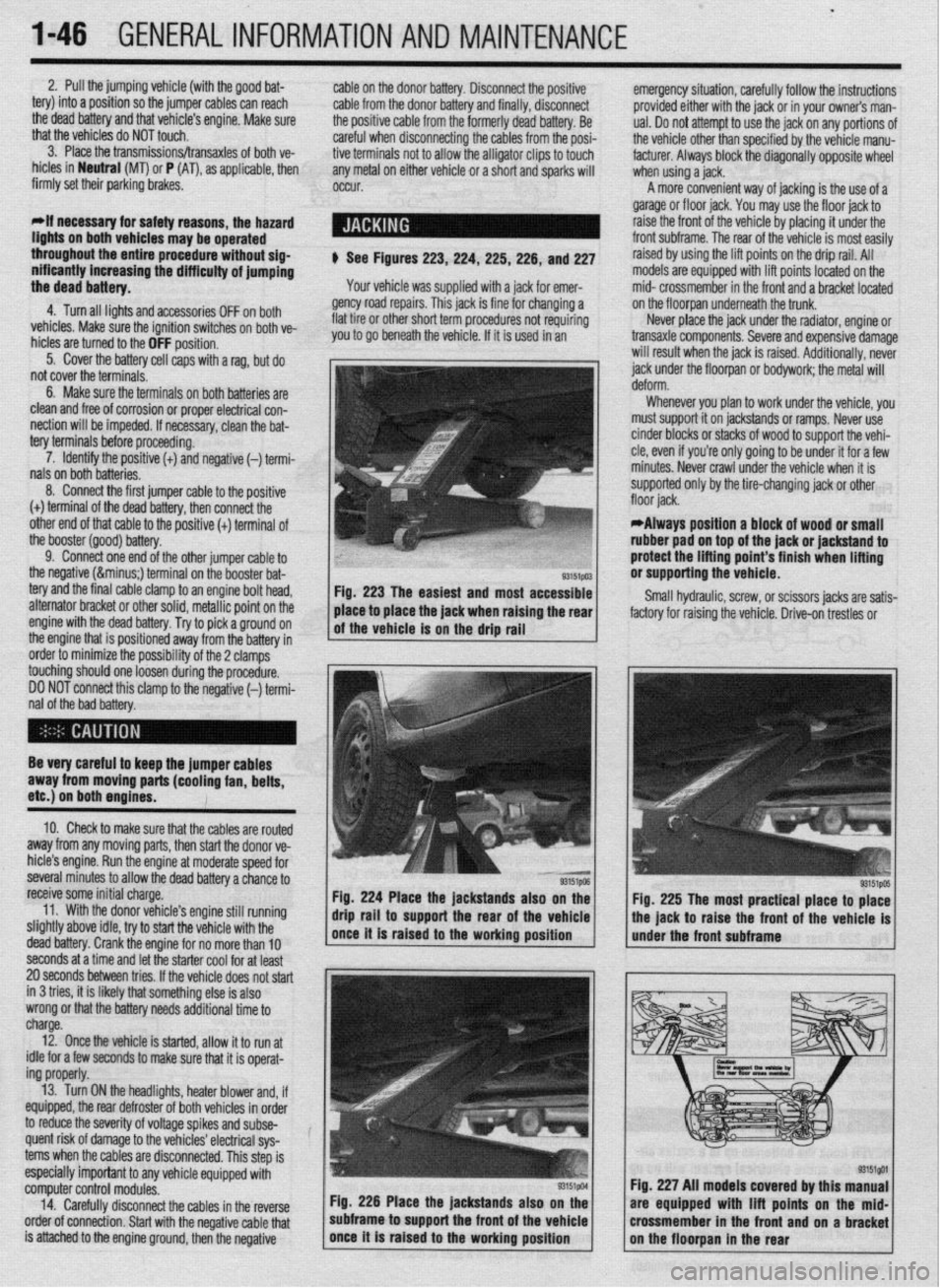
$ See Figures 223,224, 225,226, and 227
Your vehicle was supplied with a jack for emer-
gency road repairs. This jack is fine for changing a
flat tire or other short term procedures not requiring
you to go beneath the vehicle. If it is used in an emergency situation, carefully follow the instructions
provided either with the jack or in your owners man-
ual. Do not attempt to use the jack on any portions of
the vehicle other than specified by the vehicle manu-
facturer. Always block the diagonally opposite wheel
when using a jack.
A more convenient way of jacking is the use of a
garage or floor jack. You may use the floor jack to
raise the front of the vehicle by placing it under the
front subframe. The rear of the vehicle is most easily
raised by using the lift points on the drip rail. All
models are equipped with lift points located on the
mid- crossmember in the front and a bracket located
on the floorpan underneath the trunk.
Never place the jack under the radiator, engine or
transaxle components. Severe and expensive damage
will result when the jack is raised. Additionally, never
jack under the floorpan or
bodywork; the
metal will
Whenever you plan to work under the vehicle, you
must support it on jackstands or ramps. Never use
cinder blocks or stacks of wood to support the vehi-
cle, even if you’re only going to be under it for a few
minutes. Never crawl under the vehicle when it is
supported only by the tire-changing jack or other
*Always position a block of wood or small
rubber pad on top of the jack or jackstand to
protect the lifting point’s finish when lifting
or supporting the vehicle.
Small hydraulic, screw, or scissors jacks are satis-
factory for raising the vehicle. Drive-on trestles or
Be very careful to keep the jumper cables
away from moving parts (cooling fan, belts,
etc.) on both engines.
10. Check to make sure that the cables are routed
away from any moving parts, then start the donor ve-
hicle’s engine. Run the engine at moderate speed for
several minutes to allow the dead battery a chance to
receive some initial charge.
11. With the donor vehicle’s engine still running
slightly above idle, try to start the vehicle with the
dead battery. Crank the engine for no more than 10 &stands also on the
Fig. 225 The most practical place to place
front of the vehicle is
seconds at a time and let the starter cool for at least
20 seconds between tries. If the vehicle does not start
in 3 tries, it is likely thatsomething else is also
wrong or that the battery needs additional time to
charge.
12. Once the vehicle is started, allow it to run at
idle for a few seconds to make sure that it is operat-
ing properly.
13. Turn ON the headlights, heater blower and, if
equipped, the rear defroster of both vehicles in order
to reduce the severity of voltage spikes and subse-
quent risk of damage to the vehicles’ electrical sys-
tems when the cables are disconnected. This step is
especially important to any vehicle equipped with
computer control modules.
14. Carefully disconnect the cables in the’reverse
order of connection. Start with the negative cable that
is attached to the engine ground, then the negative Fig. 226 Place the jackstands also
subframe to support the front of the Fig. 227 All models covered by this
are equipped with lift points on t
crossmember in the front and on a
Page 295 of 408
.
7-16 DRIVETRAIN
11. Using puller, remove the oil seal and inner 18. While holding the rear axle shaft in positron
bearing from the trailing arm. using holding fixture tool MB9g67-01 or equivalent,
12. Inspect the companion flange and axle shaft tighten a new self-locking nut to 159 ft. Ibs. (220 Nm).
for wear or damage. Inspect the dust cover for defor- 19. Install the drive shaft nuts, washers and bolts.
mation or damage. Inspect the bearings for burning Tighten to 40-47 ft. Ibs. (55-65 Nm).
or declaration. Replace components as required 20. Install the rear brake disc, caliper assembly
To install: and parking brake.
13. Using the proper driver, press fit the inner
bearing onto the trailing arm. Press fit the oil seal
onto the trailing arm with the depression in the oil
seal facing upward, and until it contacts the shoulder
on the inner arm. 21. Install the tire and wheel assembly and lower
the vehrcle. Check the parking brake stroke and ad-
just as required.
22. Before moving the vehicle, pump the brakes
until a firm pedal is achieved.
*When tapping the oil seal in, use a plastic
hammer to lightly tap the top and circumfer-
ence of the seal installation tool, press fitting
gradually and evenly.
14. Press fit the dust covers onto the axle until it
contacts the axle shaft shoulder. Install the innermost
cover so the deDression is facino
UDWard.
REMOVAL &INSTALLATION
1. Raise the vehicle and support safely.
2. Matchmark the driveshaft and comoanion . ,
*When tapping the oil seal in, use a plastic
hammer to lightly tap the top and circumfer-
ence of the seal installation tool, press fitting
gradually and evenly. flange and remove the shaft. Don’t let it hang from the
transaxle. Tie It up to the underbody.
3. Hold the companion flange stationary and re-
move the large self-locking nut in the center of the
comoanion flanoe.
15. Apply multi-purpose grease around the entire 4: Using a Gller, remove the flange. Pry the old
circumference of the Inner side of the outer bearing seal out.
seal lip. Press fit the outer bearing to the axle shaft so
To install: that the bearrng seal lip surface is facing towards the 5. Apply a thin coat of multi-purpose grease to the
axle shaft flange. seal lip and the companion flange seal contacting sur-
16. Press fit the rear rotor to the axle shaft with face. Install the new seal with an appropriate driver.
the rear rotor groove surface towards the axle shaft 6. Install the companion flange. Install a new lock-
flange. nut and torque to 116-159 fl Ibs. (157-220 Nm). The
17. Install the rear axle shaft to the trailing arm rotation torque of the drive pinion should be about 4
temporarily. Install the companion flange to the rear inch Ibs. for new or reused, oiled bearings
axle shaft, then install a new self-locking nut. 7. Install the driveshaft.
REMOVAL &INSTALLATION
1. Raise the vehicle and support safely.
2. Drain the differential gear oil and remove the
center exhaust pipe.
3. Matchmark and remove the rear driveshaft.
4. Remove the rear halfshafts.
5. Remove the center exhaust pipe and muffler
assembly, as required.
6. Remove or disconnect the 4 wheel steering
oil pump.
7. The large mounting bolts that hold the differ-
ential carrier support plate to the underbody may use
self-locking nuts. Before removing them, support the
rear axle assembly in the middle with a transaxle
jack. Remove the nuts, then remove the support
plate(s) and the square dynamic damper from the rear
of the carrier.
8 Lower the differential carrier and remove from
the vehicle.
To install: 9. Raise the rear differential carrier into position
and install support member bolts. Install new lock-
nuts on all support bolts.
10. Install the 4 wheel steering oil pump.
11. Install new circlips on both rear driveshafts
and install.
12. Install the propeller shaft.
13. Install the center exhaust pipe and muffler.
14. Lower the vehicle.
15. With the vehicle level, fill the rear differential.
TORQUE SPECIFICATIONS Components English
Automatic Vansaxle-toengme mountrng bolts
Diamante models 54ft Ibs.
1990-92 Mrrage 3140ft Ibs.
199390 Mrrage 35ft Ibs.
1990-93 Galant 32-39 ft Ibs.
199400 Galant 35ft Ibs.
Axle hub nuts 145-188 ft tbs
Back-up lamp swatch 22-25 ft Ibs.
Clutch release fork fulcrum 25ft Ibs
Driveshaft-to-rear drfferentral flange bolts 22-25 fl lb?..
Driveshaft center bearrng support bracket mountrng nuts 22-25 fl. Ibs.
Halfshaft center bearing support bracket 33ft Ibs.
Manual transaxle-toengrne mountrng bolts
1990-92 Mtrage 3140 ft. Ibs.
1993-00 Mrrage 35 ft. Ibs.
1990-93 Galant 32-39 fl I bs.
199400 Galant 35ft Ibs.
Manual transaxle lower coupling bolt 22-25ft Ibs
Manual transaxle mount retaining nuts 32ft Ibs.
Manual transaxle mount through-bolt 51 R Ibs.
Park/neutral safety swatch retainrng bolts
1990-97 Mrrage and 1990-93 Galant 76 ft. Ibs
1994-00 Galant and 199600 Mirage afl Ibs
Dramante models
78 fl. Ibs
Pinion nut
116-159fl lb?..
Pressure plate-to-flywheel bolts
1994-98 Galant
14ft Ibs.
/
All other models 16ft Ibs.
Rear halfshaft-tocompanron flange bolts 4047ft Ibs.
Stub axle shaft hub nut 159n Ibs.
Throttle valve cable mounting nut 7-10 ft. Ibs.
Torque converter-todnveplate bolts 34-38 n. ibs
Transfer case-to-transaxle mounttng bolts
Manual transaxle
4043n Ibs.
Automatic transaxle
43-58 ft. Ibs. Metric
75 Nm
43-55 Nm
48 Nm
43-55 Nm
48 Nm
200-260 Nm
30-35 Nm
35 Nm
30-35 Nm
30-35 Nm
45 Nm
43-55 Nm
48 Nm
43-55 Nm
48 Nm
30-35 Nm
40 Nm
69 Nm
IO-12 Nm
11 Nm
IO-12 Nm
157-220 Nm
19 Nm
22 Nm
5565 Nm
220 Nm
lo-14 Nm
46-53 Nm
5560 Nm
60-80 Nm
93157co1
Page 298 of 408
SUSPENSION AND STEERiNG 8-3
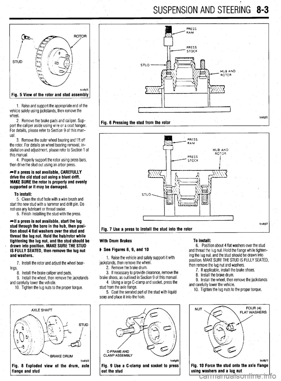
STUD
Fig. 5 View of the rotor and stud assembly
1. Raise and support the appropriate end of the
vehicle safely using jackstands, then remove the
wheel.
2. Remove the brake pads and caliper. Sup-
port the caliper aside using wire or a coat hanger.
For details, please refer to Section 9 of this man-
ual.
3 Remove the outer wheel bearing
and liff off
the rotor. For details on wheel bearing removal, in-
stallation and adjustment, please refer to Section 1 of
this manual.
4. Properly support the rotor using press bars,
then drive the stud out using an arbor press.
*If a press is not available, CAREFULLY
drive the old stud out using a blunt drift.
MAKE SURE the rotor is properly and evenly
supported or it may be damaged.
To install:
5. Clean the stud hole with a wire brush and
start the new stud with a hammer and drift pin. Do
not use any lubricant or thread sealer.
6. Finish installing the stud with the press.
*If a press is not available, start the lug
stud through the bore in the hub, then posi-
tion about 4 flat washers over the stud and
thread the lug nut. Hold the hub/rotor while
tightening the lug nut, and the stud should be
drawn into position. MAKE SURE THE STUD
IS FULLY SEATED, then remove the lug nut
and washers.
7. Install the rotor and adjust the wheel bear-
ings
8. Install the brake caliper and pads.
9. Install the wheel, then remove the jackstands
and carefully lower the vehicle.
10. Tighten the lug nuts to the proper torque.
AXLE SHAFT
Im3goa
3g. 8 Exploded view of the drum, axle
lange and stud
PRESS RAM
PRESS
STOCK
Fig. 6 Pressing the stud from the rotor
tcca$Oi Fig. 7 Use a press to install the stud into the rotor
With Drum Brakes To install:
6. Position about 4 flat washers over the stud p See Figures 8, 9, and 10
1. Raise the vehicle and safely support it with
jackstands, then remove the wheel.
2. Remove the brake drum.
3. If necessary to provide clearance, remove the
brake shoes, as outlined in Section 9 of this manual.
4. Using a large C-clamp and socket, press the
stud from the axle flange.
5. Coat the serrated part of the stud with liquid
soap and place it into the hole. and thread the lug nut. Hold the flange while tighten-
ing the lug nut, and the stud should be drawn into
position. MAKE SURE THE STUD IS FULLY SEATED,
then remove the lug nut and washers.
7. If applicable, install the brake shoes.
8. Install the brake drum.
9. Install the wheel. then remove the iackstands
and carefully lower the vehicle.
10. Tighten the lug nuts to the proper torque.
C-FRAME AND
CLAMP ASSEMBLY
Fig. 9 Use a C-clamp and socket to press
out the stud
NUT FLAT WASHERS
Fig. 10 Force the stud onto the axle flange
using washers and a lug nut
Page 320 of 408
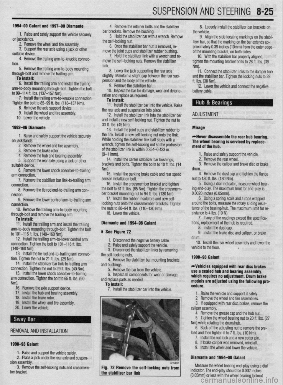
SUSPENSION AND STEERING 8-25
1994-00 Galant and 1997-00 Diamante
4. Remove the retainer bolts and the stabilizer
..- 8, Loosely in”,“,, +I?,, r+&,il;7nr kn- h.~r.l,,d” -..
1. Raise and safely support the vehicle securely he bushing.
the vehicle.
on jackstands.
7er hnr with FI wmnph Remnun (1 Alinn th
2. Remove the wheel and tire assembly.
3. Support the rear axle using a jack or other
suitable device.
4. Remove the trailing arm-to-knuckle connec-
tion,
5. Remove the trailing arm-to-body mounting
n~~““yll-““!~ (1II” fWll”“C LllG llcllllll$j a,,,,. To install:
6. Install the trailing arm and install the trailing
arm-to-body mounting through-bolt. Tighten the bolt
to 99-114 ft. Ibs. (137-157 Nm).
7. Install the trailing arm-to-knuckle connection. Dar brackets. Hemove t
5. Hold the stabilL_. __. . . _ . .._..“... ..I . .._._
the self-locking nut.
6. Once the stabilizer bar nut is removed, re-
move the joint cups and stabilizer rubber bushing.
7. Hold the stabilizer link with a wrench and re-
move the self-locking nuts. Remove the stabilizer
link.
8. Lower the jack supporting the rear axle
in a slight gap between the rear sus-
? body of the vehicle.
! the stabilizer bar.
IL_ L__ I__ _)----- .-- .-J JAI.... slightly. Mainta
pension and thf
9. Remow
10. Inspect LIIB uar 101 uamage, wear ana aereno-
ration and replace as required.
-Fe c--a-...
1 IIIJMII UK 3La”III‘w “ill “lduKm “II
“. , ,,LY,, ,,ie side locating markings on the stabi-
lizer bar, so that the marking on the bar extends ap-
proximately 0.39 inches (1Omm) from the outer edge
of the mounting bracket, on both sides.
10. With the stabilizer bar properly aligned,
tighten the mounting bracket bolts to 28 ft. Ibs. (39
Nm).
11. Connect the stabilizer links to the damper fork
andihe stabilizer bar. Tighten the locking nuts to 28
ft. Ibs. (38 Nm).
12. Lower the vehicle and connect the negative
8.. Ia
mery came.
Tighten the bolt to 85-99 ft. Ibs. (118-137 Nm).
nemove me axle suppon
9. Install the wheel and tire
10. Lower the vehicle. aewce.
assembly.
I 0 Insran: 11, Install the stabilizer bar into the vehicle. Raise
the rear axle and suspension into place.
12. Install the stabilizer link into the stabilizer ba
Ir
ADJUSTMENT anfi indc4ll 33 ft. Ibs. (45 Nm).
13. Install the ioint __-_ _.._ __
1. Raise and safely support the vehicle securely the link. Ins’
..I.,
Mlhiln hnlrii, tall a rkW self~locking n
lll~llG llUlulng the stabi” ” ’ ’ ’
wrench, tighten the self,
of the stabilizer link is v
ihe hub and bearing assembly.
5. Support the rear axle using a jack or other
suitable device.
6. Remove the lower shock absorber-to-trailing
arm connection. ocking nut. Tighten the nut to
ClrnC 2nd ?$bilizer rubber to
ut onto the link.
nzer nnK oall studs with a
-locking nut so the protrusion
within 0.354-0.433 in.
I stabilizer bar bushings,
>+nn thn hnk In -I A u (9-llmm).
14. Install the cente
brackets and bolts. Tiqt Mirage
*Never disassemble the rear hub bearing.
The wheel bearing is serviced by replace-
ment of the hub.
1. Raise and safely support the vehicle.
2. Remove the rear wheel.
3. Remove the caliper and brake disc of brake 1992-96 biamante
on IacKsranos.
2. Remove the wheel and tire assembly
3, Remove thn hralm rntnr 4. Remove1
7. Remove the stabilizer bar link-to-trailing arm
connection.
8. Remove the tie rod end-to-trailing arm con-
nection.
9. Remove the lower control arm-to-trailing arm
connection.
10. Remove the trailing arm-to-body mounting
through-bolt and remove the trailing arm. Nm).
15. Install the parking
sensor installation bolt.
, , I oraxe cat * ale ar
member bracket and tighten
i Nm). Tighten the crossmem-
A to 94 ft. Ibs. (130 Nm). 16. Install the cross
the bolt to 61 ft. Ibs. (8!
ber bracket mounting nl
17. Install the rubbe
locking nuts onto the cro:
the nuts to 80-94 fl. Ibs. (
18. Lower the vehicle. id rear speed drum.
4. Remove the dust cab and tighten the flange ll”, *lb+ to 130 ft. Ibs. (180 Nm).
5. Using a dial indicator, measure wheel bear-
!r insulators and new seif-
ismemoer ’ brackets. Tighten
[110-130 Nm). ing end-play. The maximum limit for end-play is
o.oc-- ‘^ -- rzu mcnes (u.usmm).
arol
tanc
sisk 6. Using a spring scale and a rope wrapped
md the bolts, measure the rotary sliding resis-
e of the bearing/hub. The maximum limit for re-
mce is 4 Ibs. (19 N).
7. If any of the readings exceed the specifica-
To install:
11. Install the trailing arm and install the trailina Diamante and 1994-98 Gal&i
t tions, replacement of the hub is required.
8. Install the dust cap.
9. Install the brake disc and caliper, or brake
negative battery ( sble.
;“I,-.
I support the vbhlblG.
stabilizer links by removing
Alizer bar mounting brackets
from the vehicle.
lonents for wear or damage,
ded. drum.
10. Install the rear wheel assembly and lower the
vehicle to the floor.
*
1990-93 Galant
*Vehicles equipped with rear disc brakes
use a sealed hub and bearing assembly,
which requires no adjustment. Drum brake
models are
adjusted using the following pro- arm-to-body mounting through-bolt. Tighten the bolt
to 101-116 ft. Ibs. (140-160 Nm). ) See Figure 72
12. Install the trailing arm-to-lower control arm
1. Disconnect the I
connection. Tighten the bolt to 101-116 ft. Ibs.
(140-160 Nm). 2. Raise and safely
13. Install the tie rod end-to-trailing arm connec- 3. Disconnect the I
tion. Tighten the nut to 21 ft. Ibs. (29 Nm). the self-locking nuts.
14. Install the stabilizer bar link-to-trailing arm 4. Remove the stat
connection. Tighten the nut to 29 ft. Ibs. (40 Nm). and bushings.
15. Install the lower shock absorber-to-trailing
5. Remove the bar
arm connection. Tighten the bolt to 65 ft. Ibs. (90 6. Inspect all comr
. and replace parts as nee
Nrn).
16. Remove the axle support device.
17. Install the hub and bkaring assembly,
18. Install the brake rotor.
19. Install the wheel and tire assembly.
20. Lower the vehicle.
REMOVALANDINSTALLATION
1990-93 Gaiant
1. Raise and support the vehicle safely.
2. Place a jack under the rear axle and suspen- To install:
7 InstA the dnhili cedure. ._._ . . .._ -.--.. lzer bar into the vehicle.
1. Raise the vehicle and support it safely.
2. Remove the wheel and tire assemblies.
3. If equipped with rear disc brakes, remove the
caliper assembly.
4. Remove the grease cap and the hub nut.
5. Tighten the wheel bearing nut to 20 ft. Ibs. (27
Nm) while rotatir ” ”
6. Back off th
load and then tighten it to 7 ft. Ibs. (10 Nm).
7. Install the nut lock and a new cotter pin.
8. If brake caliper was removed, reinstall.
9. Install the wheel and lower the vehicle.
Diamante and lQQ44 Galant 10 tne mum/hub.
ie adjusting nut to remove the pre-
Sian assembly.
3. Remove the self-locking nuts and crossmem-
ber bracket.
93158P61 Fig. 72 Remove the self-locking nuts from Measure the wheel bearing end-play using a dial
the stabilizer bar link indicator. The end-play should be 0.002 inches
a (0.05mm) or less with the wheel bearing locknut
Page 321 of 408
SUSPENSION AND STEERING 8-25
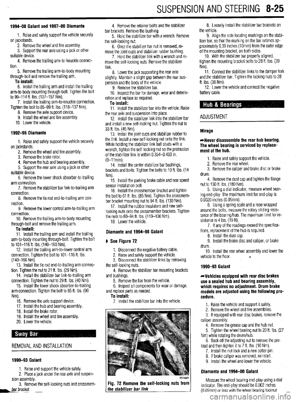
1994-00 Galant and 1997-00 Diamante
1, Raise and safely support the vehicle securely
on jackstands.
2. Remove the wheel and tire assembly.
3. Support the rear axle using a jack or other
suitable device.
4. Remove the trailing arm-to-knuckle connec-
tion.
5. Remove the trailing arm-to-body mounting
through-bolt and remove the trailing arm.
To install: 6. Install the trailing arm and install the trailing
arm-to-body mounting through-bolt. Tighten the bolt
to 99-114 ft. lbs. (137-157 Nm).
7. Install the trailing arm-to-knuckle connection.
Tighten the bolt to 85-99 ft. Ibs. (118-137 Nm).
8. Remove the axle support device.
9. install the wheel and tire assembly.
10. Lower the vehicle.
1992-96 Diamante
1. Raise and safely support the vehicle securely
on jackstands.
2. Remove the wheel and tire assembly.
3. Remove the brake rotor.
4. Remove the hub and bearing assembly.
5. Support the rear axle using a jack or other
suitable device.
6. Remove the lower shock absorber-to-trailing
arm connection.
7. Remove the stabilizer bar link-to-trailing arm
connection.
8. Remove the tie rod end-to-trailing arm con-
nection.
9. Remove the lower control arm-to-trailing arm
connection.
10. Remove the trailing arm-to-body mounting
through-bolt and remove the trailing arm.
To install: 11, Install the trailing arm and install the trailing
arm-to-body mounting through-bolt. Tighten the bolt
to lOl-116ft. Ibs. (14C-160 Nm).
12. Install the trailing arm-to-lower control arm
connection. Tighten the bolt to 101-116 ft. Ibs.
(140-l 60 Nm).
13. Install the tie rod end-to-trailing arm connec-
tion. Tighten the nut to 21 ft. Ibs. (29 Nm).
14. Install the stabilizer bar link-to-trailina arm
connection. Tighten the nut to 29 ft. Ibs. (40 im).
15. Install the lower shock absorber-to-trailing
arm connection. Tighten the bolt to 65 ft. Ibs. (90
Nm).
16. Remove the axle support device.
17. Install the hub and bearing assembly.
18. Install the brake rotor.
19. Install the wheel and tire assembly.
20. Lower the vehicle.
REMOVALANDINSTALLATION '
1990-93 Galant
1. Raise and support the vehicle safely.
2. Place a jack under the rear axle and suspen-
sion assembly.
3. Remove the self-locking nuts and crossmem-
her bracket.
d.--- -.
Fig. 72 Remove the self-locking nuts from
the stabilizer bar link 8. Loosely install the stabilizer bar brackets on
the vehicle.
9. Align the side locating markings on the stabi-
lizer bar, so that the marking on the bar extends ap-
proximately 0.39 inches (1Omm) from the outer edge
of the mounting bracket, on both sides.
10. With the stabilizer bar properly aligned,
tighten the mounting bracket bolts to 28 ft. Ibs. (39
Nm).
11. Connect the stabilizer links to the damper fork
andjhe stabilizer bar. Tighten the locking nuts to 28
ft. Ibs. (38 Nm).
12. Lower the vehicle and connect the negative
battery cable.
ADJUSTMENT
1990-93 Galant
*Vehicles equipped with rear disc brakes
use a sealed hub and bearing assembly,
which requires no adjustment. Drum brake
models are adjusted using the following pro-
cedure.
1. Raise the vehicle and support it safely.
2. Remove the wheel and tire assemblies.
3. If equipped with rear disc brakes, remove the
caliper assembly.
4. Remove the grease cap and the hub nut.
5. Tighten the wheel bearing nut to 20 ft. Ibs. (27
Nm) while rotating the drum/hub.
6. Back off the adjusting nut to remove the pre-
load and then tighten it to 7 ft. Ibs. (10 Nm).
7. Install the nut lock and a new cotter pin.
8. If brake caliper was removed, reinstall.
9. Install the wheel and lower the vehicle.
Diamante and 1994-00 Galant
Measure the wheel bearing end-play using a dial
indicator. The end-play should be 0.002 inches
(0.05mm) or less with the wheel bearing locknut _
Page 322 of 408
8-26 SUSPENSION AND STEERING
torqued to specifications. The wheel bearings are
sealed units and are not adjustable. If defective, re-
placement is the only option.
REMOVAL &INSTALLATION
Mirage
7996-92 MODELS
1. Raise the vehicle and support safely.
2. Remove the tire and wheel assembly.
3. If equipped with rear disc brakes, remove the
caliper from the disc and remove the brake disc.
4. Remove the dust cap and bearing nut. Do not
use an air gun to remove the nut.
5. Remove the outer wheel bearing.
6. Remove the drum and/or axle hub with the
inner wheel bearing and the grease seal.
7. Remove the grease seal and remove the inner
bearing.
To install: 8. Lubricate the inner bearing and install to the
drum or hub.
9. Install a new grease seal.
10. To determine if the self-locking nut is
reusable:
a. Screw in the self-locking nut until about
0.07-0.11 in. (2-3mm) of thread is visible under
the nut.
b. Measure the torque required to turn the
self-locking nut counterclockwise.
c. The lowest allowable torque is 48 inch Ibs.
(6 Nm). If the measured torque is less than the
specification, replace the nut.
11. Install the drum and/or hub to the vehicle.
12. Lubricate and install the outer wheel bearing
to the spindle.
13. Tighten the self-locking nut to 108-145 ft.
Ibs. (150-200 Nm).
14. Set up a dial indicator and measure the end-
play while moving the hub or drum in and out. If the
endplay exceeds 0.008 in. (0.002mm) retorque the
nut. If still beyond the limit, replace the bearings.
15. Install the grease cap and wheel assembly.
7993-60 MODELS
*Never disassemble the rear hub bearing.
The wheel bearing is serviced by replace-
ment of the hub.
1. If equipped with ABS, remove the wheel
speed sensor.
2. Raise and safely support the vehicle.
3. Remove the rear wheel.
4. Remove the caliper and brake disc or brake
drum.
5. Remove the dust cap and flange nut.
6. Remove the rear hub assembly.
To install: 7. Install the rear hub assembly using a new
flange nut. Tighten the flange nut to 130 ft. Ibs. (180
Nm).
8. install the dust cap.
9. Install the wheel speed sensor if removed.
The air gap should be 0.012-0.035 in. (0.3-0.9mm).
10. Install the brake disc and caliper, or brake
drum.
11. Install the rear wheel assembly and lower the
vehicle to the floor.
1990-93 Galant
DRUM BRAKE VEHICLES
1. Raise the vehicle and support it safely.
2. Remove the wheel and tire assemblies.
3. Remove the grease cap and the hub nut.
4. Remove the brake drum. The outer bearing
will fall out while the drum is coming off. Do not drop
it. Remove the hub and rotor assembly.
5. Pry out and discard the oil seal.
6. Remove the inner bearing.
*Check the bearing races. If any scoring,
heat checking or damage is noted, they
should be replaced. When bearing or races
need replacement, replace them as a set.
7. If the bearings and races are to be replaced,
drive out the race with a brass drift.
To install: 8. Before installing new races, coat them with
wheel bearing grease. Drive into place with proper
size driver. Make sure they are fully seated.
9. Thoroughly pack the bearings and lubricate
the hubs with wheel bearing grease. Install the inner
bearing and coat the lip and rim of the grease seal
with grease. Drive the seal into place with a seal dri-
ver.
10. Install the drum assembly on the axle.
11, Lubricate and install the outer wheel bearing,
washer and nut. To properly adjust the wheel bearing
preload:
a. Tighten the wheel bearing nut to 20 ft. Ibs.
(27 Nm) while rotating the drum.
b. Back off the adjusting nut to remove the
preload, then tighten it to 7 ft. Ibs. (10 Nm).
c. Install the nut lock and a new cotter pin.
12. Install the wheel and lower the vehicle.
O/SC BRAKE VEHICLES
1. Raise the vehicle and support safely.
2. Remove the tire and wheel assembly.
3. Remove the bolt(s) holding the speed sensor
bracket to the knuckle and remove the assembly from
the vehicle.
The speed sensor has a pole piece projecting
from it. This exposed tip must be protected
from impact or scratches. Do not allow the
oole oiece to contact the toothed wheel dur-
in0 removal or installation.
4. Remove the caliper from the brake disc and
suspend with a wire.
5. Remove the brake rotor.
6. Remove the grease cap, locking nut and
tongued washer.
7. Remove the rear hub and bearing assembly.
*The rear hub assembly can not be disas-
sembled. If bearing replacement is required,
replace the assembly as a unit.
8. If replacing the hub assembly, remove the
two bolts securing the speed sensor ring to the hub.
To install: 9. Install the speed sensor to the hub and bear-
ing assembly. Tighten the mounting bolts to 8 ft. Ibs.
(11 Nm). 10. Install the hub and bearing assembly to the
axle shaft.
11, Install the tongued washer and a new locking
nut. Tighten the locknut to 144-188 ft. Ibs. (200-260
Nm). Once the locknut has been properly torqued,
crimp the nut flange over the slot in the spindle, and
install the grease cap.
12. Install the brake caliper and rotor.
13. Install the speed sensor and tighten the
mounting bolt to 8 ft. Ibs. (11 Nm).
14. Install the tire and wheel assembly.
Be sure to pump the brake pedal until it’s
firm, before moving vehicle.
1994-00 Galant
DRUM BRAKE VEHICLES
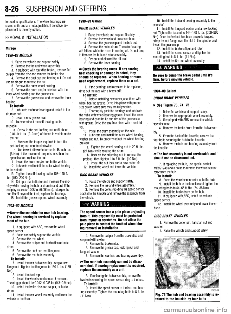
) See Figure 73, 74, 75
1. Raise the vehicle and support safely.
2. Remove the appropriate wheel assembly.
3. If equipped with ABS, remove the vehicle
speed sensor.
4. Remove the brake drum from the hub assem-
bly.
5. From the back of the knuckle, remove the
four bolts securing the hub to the knuckle.
6. Remove the hub and bearing assembly from
the knuckle.
*The hub assembly is not serviceable and
should not be disassembled.
7. If replacing the hub, use special socket
MB991248 and a press to remove the wheel sensor
rotor from the hub.
To install: 8. Press the wheel sensor rotor onto the hub.
9. Install the hub to the knuckle and tighten the
mounting bolts to 54-65 ft. Ibs. (74-88 Nm).
10. Install the brake drum on the hub.
11. If equipped with ABS, install the vehicle
speed sensor.
12. Install the wheel assembly and lower the ve-
hicle.
O/SC BRAKE VEHICLES
1. Remove the cotter pin, halfshaft nut and
washer.
2. Raise the vehicle and support safely.
Fig. 73 The hub and bearing assembly is re-
tained to the knuckle by four bolts