1900 MITSUBISHI DIAMANTE jack points
[x] Cancel search: jack pointsPage 45 of 408

.
I-46 GENERALINFORMATIONAND MAINTENANCE
2. Pull the jumping vehicle (with the good bat-
tery) into a position so the jumper cables can reach
the dead battery and that vehicle’s engine. Make sure
that the vehicles do NOT touch.
3. Place the transmissions/transaxles of both ve-
hicles in Neutral (MT) or P (AT), as applicable, then
firmly set their parking brakes.
*ff necessary for safety reasons, the hazard
lights on both vehicles may be operated
throughout the entire procedure without sig-
nificantiy increasing the diff icuity of jumping
the dead battery.
4. Turn all lights and accessories OFF on both
vehicles. Make sure the ignition switches on both ve-
hicles are turned to the OFF position.
5. Cover the battery cell caps with a rag, but do
not cover the terminals.
6. Make sure the terminals on both batteries are
clean and free of corrosion or proper electrical con-
nection will be impeded. If necessary, clean the bat-
tery terminals before proceeding.
7. Identify the positive (+) and negative (-) termi-
nals on both batteries.
8. Connect the first jumper cable to the positive
(t) terminal of the dead battery, then connect the
other end of that cable to the positive (t) terminal of
the booster (good) battery.
9. Connect one end of the other jumper cable to
the negative (−) terminal on the booster bat-
tery and the final cable clamp to an engine bolt head,
alternator bracket or other solid, metallic point on the
engine with the dead battery. Try to pick a ground on
the engine that is positioned away from the battery in
order to minimize the possibility of the 2 clamps
touching should one loosen during the procedure.
DO NOT connect this clamp to the negative (-) termi-
nal of the bad battery. cable on the donor battery. Disconnect the positive
cable from the donor battery and finally, disconnect
the positive cable from the formerly dead battery. Be
careful when disconnecting the cables from the posi-
tive terminals not to allow the alligator clips to touch
any metal on either vehicle or a short and sparks will
occur.
I
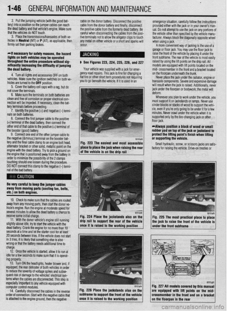
$ See Figures 223,224, 225,226, and 227
Your vehicle was supplied with a jack for emer-
gency road repairs. This jack is fine for changing a
flat tire or other short term procedures not requiring
you to go beneath the vehicle. If it is used in an emergency situation, carefully follow the instructions
provided either with the jack or in your owners man-
ual. Do not attempt to use the jack on any portions of
the vehicle other than specified by the vehicle manu-
facturer. Always block the diagonally opposite wheel
when using a jack.
A more convenient way of jacking is the use of a
garage or floor jack. You may use the floor jack to
raise the front of the vehicle by placing it under the
front subframe. The rear of the vehicle is most easily
raised by using the lift points on the drip rail. All
models are equipped with lift points located on the
mid- crossmember in the front and a bracket located
on the floorpan underneath the trunk.
Never place the jack under the radiator, engine or
transaxle components. Severe and expensive damage
will result when the jack is raised. Additionally, never
jack under the floorpan or
bodywork; the
metal will
Whenever you plan to work under the vehicle, you
must support it on jackstands or ramps. Never use
cinder blocks or stacks of wood to support the vehi-
cle, even if you’re only going to be under it for a few
minutes. Never crawl under the vehicle when it is
supported only by the tire-changing jack or other
*Always position a block of wood or small
rubber pad on top of the jack or jackstand to
protect the lifting point’s finish when lifting
or supporting the vehicle.
Small hydraulic, screw, or scissors jacks are satis-
factory for raising the vehicle. Drive-on trestles or
Be very careful to keep the jumper cables
away from moving parts (cooling fan, belts,
etc.) on both engines.
10. Check to make sure that the cables are routed
away from any moving parts, then start the donor ve-
hicle’s engine. Run the engine at moderate speed for
several minutes to allow the dead battery a chance to
receive some initial charge.
11. With the donor vehicle’s engine still running
slightly above idle, try to start the vehicle with the
dead battery. Crank the engine for no more than 10 &stands also on the
Fig. 225 The most practical place to place
front of the vehicle is
seconds at a time and let the starter cool for at least
20 seconds between tries. If the vehicle does not start
in 3 tries, it is likely thatsomething else is also
wrong or that the battery needs additional time to
charge.
12. Once the vehicle is started, allow it to run at
idle for a few seconds to make sure that it is operat-
ing properly.
13. Turn ON the headlights, heater blower and, if
equipped, the rear defroster of both vehicles in order
to reduce the severity of voltage spikes and subse-
quent risk of damage to the vehicles’ electrical sys-
tems when the cables are disconnected. This step is
especially important to any vehicle equipped with
computer control modules.
14. Carefully disconnect the cables in the’reverse
order of connection. Start with the negative cable that
is attached to the engine ground, then the negative Fig. 226 Place the jackstands also
subframe to support the front of the Fig. 227 All models covered by this
are equipped with lift points on t
crossmember in the front and on a
Page 46 of 408

GENERAL INFORMATION AND MAINTENANCE 1-47
ramps are also a handy and safe way to both raise l When the drive wheels are to remain on the
and support the vehicle. Be careful though, some ground, leave the vehicle in gear to help prevent it
ramps may be too steep to drive your vehicle onto
The following safety points cannot be overempha- from rolling.
without scraping the front bottom panels. Never sup-
sized:
l Always use jackstands to support the vehicle
port the vehicle on any suspension member (unless l Always block the opposite wheel or wheels to when you are working underneath. Place the stands
specifically instructed to do so by a repair manual) or
keep the vehicle from rolling off the jack. beneath the vehrcle’s jacking brackets Before climb-
by an underbody panel.
l When raising the front of the vehicle, firmly ap- ing underneath, rock the vehicle a bit to make sure it
ply the parking brake. is firmly supported.
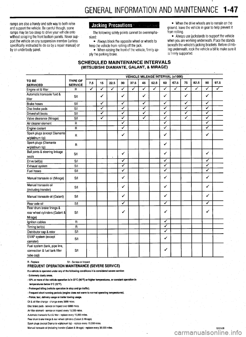
SCHEDULED MAINTENANCE INTERVALS (MITSUBISHI DIAMANTE, GALANT, & MIRAGE)
VEHICLE MILEAGE INTERVAL (x1000)
7.5 15
22.5 30 37.5 45 52.5 60 67.5 75 62.5 90 97.5
J J
J 4 J J 4 4 4 J J
J 4
4
J J J J 4 TO BE
Ball loints &steering linkage
S/I J J J
seals
Dnve belt(s) S/I 4 4 J
Fvha,,rt cvctom $/I
J J J LmI,..“w. “,YL”,‘. Fuel hoses
+
Manual transaxle oil (Galant)
connectlon & fuel tank filler
R. Replace S/I - Sefwce or Inspect FREQUENT OPERATION MAINTENANCE (SEVERE SERVICE) II a vehicle is operated under any of the following conditions it is considered severe service:
- Extremely dusty areas.
- 50% or more of the vehicle operation is in 32% (WF) or higher temperatures, or constant opsralion in
temperatures below 0% (32°F).
- Prolonged idling (vehicle operation in stop and go traffic).
_ Frequent short running periods (engine does not warm to normal operating temfwatures).
- Police, taxi, delivery usage or trailer towing usage.
0118 011 filter change-change every 3CQO miles.
Disc brake pads - sewce or Inspect ever 6COO miles
AN hlter element _ setwe or inspect every 15,000 miles.
Automatic transaxle lluld 8 filter . replace every 15,COO m&s.
Rear drum brake Ikmngs & rear wheel cylinders (Galant & Mirage)
Spark plugs (except Dlamante wlplabnum tip) - replace every 15,COO miles.
Manual transaxle 011 (mcludlng transfer (Galant & Mirage). replace every 30,000 miles.
Page 297 of 408

.
8-2 SUSPENSION AND STEERING
b
REMOVAL &INSTALLATION
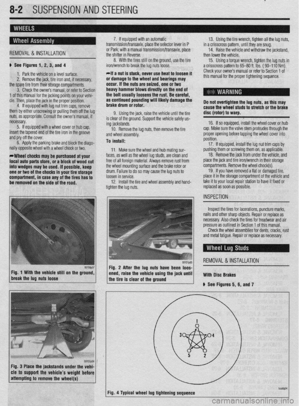
# See Figures 1, 2, 3, and 4
1. Park the vehicle on a level surface.
2. Remove the jack, tire iron and, if necessary,
the spare tire from their storage compartments.
3. Check the owners manual, or refer to Section
1 of this manual for the jacking points on your vehi-
cle. Then, place the jack in the proper position,
4. If equipped with lug nut trim caps, remove
them by either unscrewing or pulling them off the lug
nuts, as appropriate. Consult the owners manual, if
necessary.
5. If equipped with a wheel cover or hub cap,
insert the tapered end of the tire iron in the groove
and pry off the cover.
6. Apply the parking brake and block the diago-
nally opposite wheel with a wheel chock or two.
*Wheel chocks may be purchased at your
local auto parts store, or a block of wood cut
into wedges may be used. If possible, keep
one or two of the chocks in your tire storage
compartment, in case any of the tires has to
be removed on the side of the road. 7. If equipped with an automatic
transmission/transaxle, place the selector lever in P
or Park; with a manual transmission/transaxle, place
the shifter in Reverse.
8. With the tires still on the ground, use the tire
iron/wrench to break the lug nuts loose.
*If a nut is stuck, never use heat to loosen it
or damage to the wheel and bearings may
occur. If the nuts are seized, one or two
heavy hammer blows directly on the end of
the bolt usually loosens the rust. Be careful,
as continued pounding will likely damage the
brake drum or rotor.
9. Using the jack, raise the vehicle until the tire
is clear of the ground. Support the vehicle safely us-
ing jackstands.
10. Remove the lug nuts, then remove the tire
and wheel assembly.
To install:
11. Make sure the wheel and hub mating sur-
faces, as well as the wheel lug studs, are clean and
free of all foreign material. Always remove rust from
the wheel mounting surface and the brake rotor or
drum. Failure to do so may cause the lug nuts to
loosen in service.
12. Install the tire and wheel assembly and hand-
tighten the lug nuts. 13. Using the tire wrench, tighten all the lug nuts,
in a crisscross pattern, until they are snug.
14. Raise the vehicle and withdraw the jackstand,
then lower the vehicle.
15. Using a torque wrench, tighten the lug nuts in
a crisscross pattern to 65-80 ft. lbs. ( 90-l 10 Nm).
Check your owners manual or refer to Section 1 of
this manual for the proper tightening sequence.
Do not overtighten the lug nuts, as this may
cause the wheel studs to stretch or the brake
disc (rotor) to warp.
16. If so equipped, install the wheel cover or hub
cap. Make sure the valve stem protrudes through the
proper opening before tapping the wheel cover into
position.
17. If equipped, install the lug nut trim caps by
pushing them or screwing them on, as applicable.
18. Remove the jack from under the vehicle, and
place the jack and tire iron/wrench in their storage
compartments. Remove the wheel chock(s).
19. If you have removed a flat or damaged tire,
place it in the storage compartment of the vehicle and
take it to your local repair station to have it fixed or
replaced as soon as possible.
Inspect the tires for lacerations, puncture marks,
nails and other sharp objects. Repair or replace as
necessary. Also check the tires for treadwear and air
pressure as outlined in Section 1 of this manual.
Check the wheel assemblies for dents, cracks, rust
and metal fatigue. Repair or replace as necessary.
REMOVAL&INSTALLATION
Fig. 3 Place the jackstands under the vehi-
cle to support the vehicle’s weight before
Page 359 of 408

BRAKES 9-23
1. Make sure the parking brake cable is free and
is not frozen or sticking.
2. Apply the parking brake with 45 Ibs. (200 N) of
force while counting the number of notches. The de-
sired parking brake stroke should be 5-7 notches.
3. If adjustment is required, access the adjusting
nut from inside the floor console.
4. Loosen the locknut on the cable rod.
5. Rotate the adjusting nut to adjust the parking
brake stroke to the 5-7 notch setting. After making
the adjustment, check there is no looseness between
the adjusting nut and the parking brake lever, then
tighten the locknut.
*Do not adjust the parking brake too tight. If
the number of notches is less than specifica-
tion, the cable has been pulled too much and
the automatic adjuster will fail or the brakes
will drag.
6. After adjusting the lever stroke, raise the rear of
the vehicle and safely support. With the parking brake
lever in the released position, turn the rear wheels to
confirm that the rear brakes are not dragging.
7. Check that the parking brake holds the vehicle
on an incline.
Galant
‘ 1990-93 VEHICLES
# See Figure 111
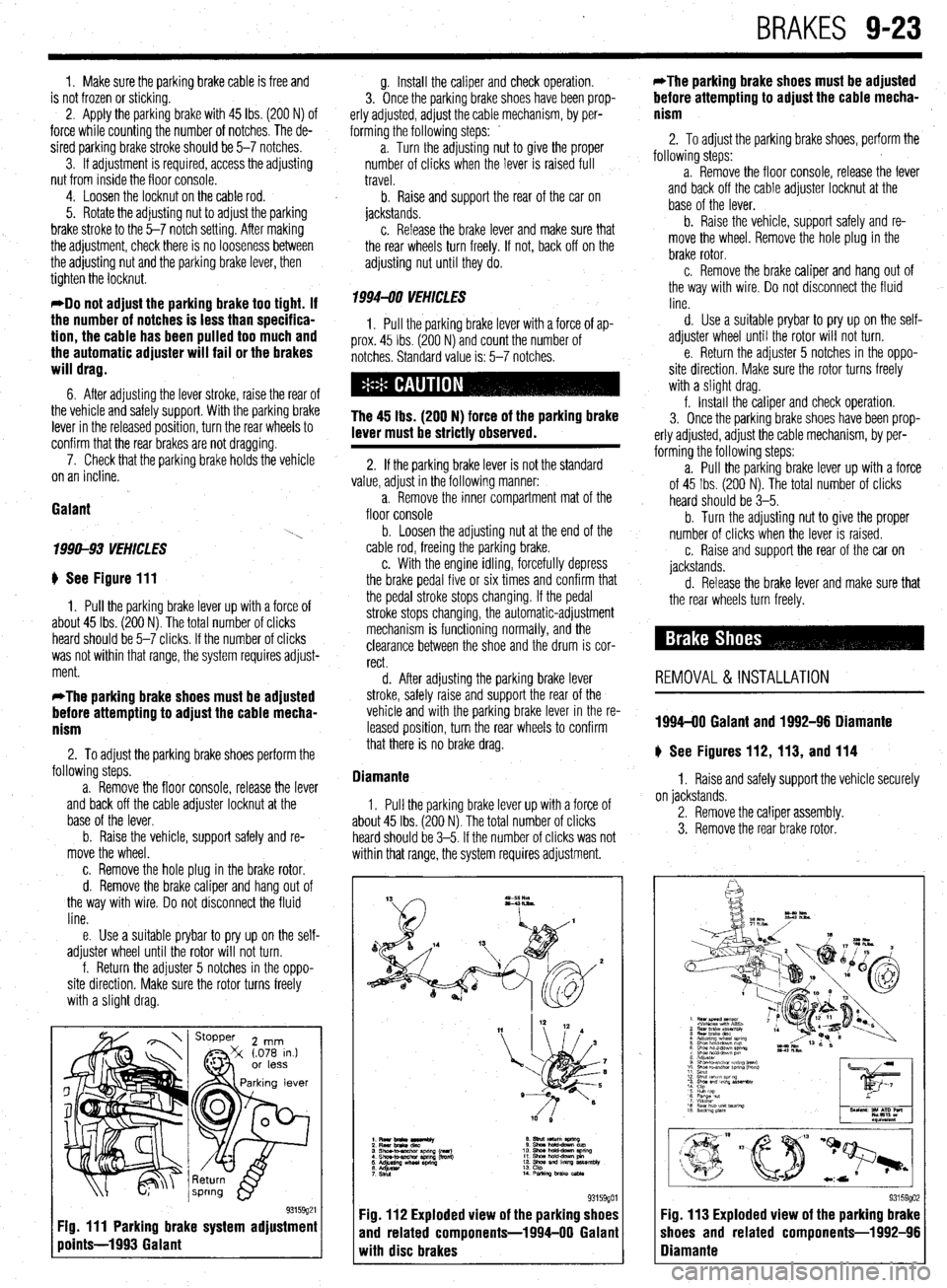
1. Pull the parking brake lever up with a force of
about 45 Ibs. (200 N). The total number of clicks
heard should be 5-7 clicks. If the number of clicks
was not within that range, the system requires adjust-
ment.
*The parking brake shoes must be adjusted
before attempting to adjust the cable mecha-
nism
2. To adjust the parking brake shoes perform the
following steps.
a. Remove the floor console, release the lever
and back off the cable adjuster locknut at the
base of the lever.
b. Raise the vehicle, support safely and re-
move the wheel.
c. Remove the hole plug in the brake rotor.
d. Remove the brake caliper and hang out of
the way with wire. Do not disconnect the fluid
line.
e. Use a suitable prybar to pry up on the self-
adjuster wheel until the rotor will not turn.
f. Return the adjuster 5 notches in the oppo-
site direction. Make sure the rotor turns freely
with a slight drag.
Fig. 111 Parking brake system adjustment
points-1993 Galant
g. Install the caliper and check operation.
3. Once the parking brake shoes have been prop-
erly adjusted, adjust the cable mechanism, by per-
forming the following steps: _
a. Turn the adjusting nut to give the proper
number of clicks when the lever is raised full
travel.
b. Raise and support the rear of the car on
jackstands.
c. Release the brake lever and make sure that
the rear wheels turn freely. If not, back off on the
adjusting nut until they do.
1994470 VEHICLES
1, Pull the parking brake lever with a force of ap-
prox. 45 Ibs. (200 N) and count the number of
notches. Standard value is: 5-7 notches.
The 45 lbs. (200 N) force of the parking brake
lever must be strictly observed.
2. If the parking brake lever is not the standard
value, adjust in the following manner:
a. Remove the inner compartment mat of the
floor console
b. Loosen the adjusting nut at the end of the
cable rod, freeing the parking brake.
c. With the engine idling, forcefully depress
the brake pedal five or six times and confirm that
the pedal stroke stops changing. If the pedal
stroke stops changing, the automatic-adjustment
mechanism is functioning normally, and the
clearance between the shoe and the drum is cor-
rect.
d. After adjusting the parking brake lever
stroke, safely raise and support the rear of the
vehicle and with the parking brake lever in the re-
leased position, turn the rear wheels to confirm
that there is no brake drag.
Diamante
1. Pull the parking brake lever up with a force of
about 45 Ibs. (200 N). The total number of clicks
heard should be 3-5. If the number of clicks was not
within that range, the system requires adjustment.
93159901 Fig. 112 Exploded view of the parking shoes
and related components-1994-00 Galant
with disc brakes *The parking brake shoes must be adjusted
before attempting to adjust the cable mecha-
nism
2. To adjust the parking brake shoes, perform the
following steps: -
a. Remove the floor console, release the lever
and back off the cable adjuster locknut at the
base of the lever.
b. Raise the vehicle, support safely and re-
move the wheel. Remove the hole plug in the
brake rotor.
c. Remove the brake caliper and hang out of
the way with wire, Do not disconnect the fluid
line.
d. Use a suitable prybar to pry up on the self-
adjuster wheel until the rotor will not turn.
e. Return the adjuster 5 notches in the oppo-
site direction, Make sure the rotor turns freely
with a slight drag.
f. Install the caliper and check operation.
3. Once the parking brake shoes have been prop-
erly adjusted, adjust the cable mechanism, by per-
forming the following steps:
a. Pull the parking brake lever up with a force
of 45 Ibs. (200 N). The total number of clicks
heard should be 3-5.
b. Turn the adjusting
nut to give the proper
number of clicks when the lever is raised.
c. Raise and support the rear of the car on
jackstands.
d. Release the brake lever and make sure
that the rear wheels turn freely.
REMOVAL &INSTALLATION
1994-00 Galant and 1992-96 Diamante
# See Figures 112, 113, and 114
1. Raise and safely support the vehicle securely
on jackstands.
2. Remove the caliper assembly.
3. Remove the rear brake rotor.
I
I 93159902 Fig. 113 Exploded view of the parking brake
shoes and related components-1992-96
Diamante