1900 MITSUBISHI DIAMANTE checking oil
[x] Cancel search: checking oilPage 3 of 408
GENERALINFORMATIONAND MAINTENANCE l-3
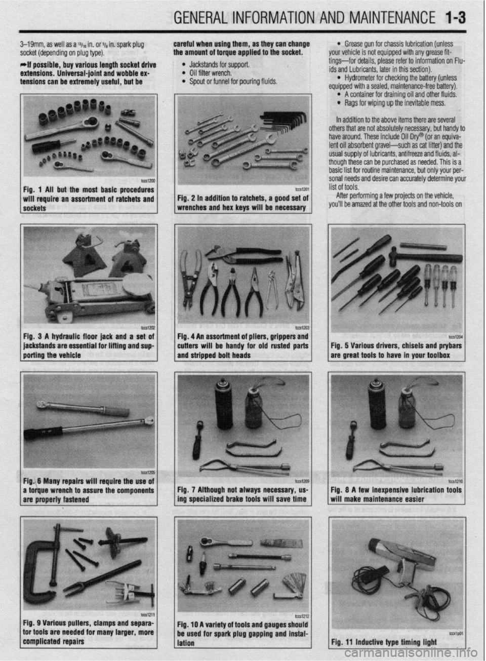
3-19mm, as well as a % in. or ~/a in. spark plug careful when using them, as they can change
socket (depending on plug type). the amount of torque applied to the socket.
-if possible, buy various length socket drive
l Jackstands for support.
extensions. Universal-joint and wobble ex- l Oil filter wrench.
tensions can be extremely useful, but be l Spout or funnel for pouring fluids.
l Grease gun for chassis lubrication (unless
your vehicle is not equipped with any grease fit-
tings-for details, please refer to information on Flu-
ids and Lubricants, later in this section).
l Hydrometer for checking the battery (unless
equiooed with a sealed, maintenance-free batten/).
In addition to the above items there are several O’ A container for draining oil and other fluids.
l Rags for wiping up the inevitable mess.
pi 1 others that are not absolutely necessary, but handy to
have around. These include Oil Dry@ (or an equiva-
lent oil absorbent gravel-such as cat litter) and the
usual SUDDIV of lubricants. antifreeze and fluids. al-
though the.& can be purchased as needed. This is a
basic list for routine maintenance, but only your per-
sonal needs and desire can accurately determine your
Fig. 1 Ail but the most basic procedures
After performing a few projects on the vehicle,
you’ll be amazed at the other tools and non-tools on
lWSl2U2 Fig, 3 A hydraulic floor jack and a set of
jackstands are essential for lifting and sup
porting the vehicle tm1204 Fig. 5 Various drivers, chisels and ptybars
are great tools to have in your toolbox
Fig. 7 Although not always necessary, us-
ing specialized brake tools will save time
Fig. 11 inductive type timing light
Page 20 of 408
GENERALINFORMATIONAND MAINTENANCE l-21
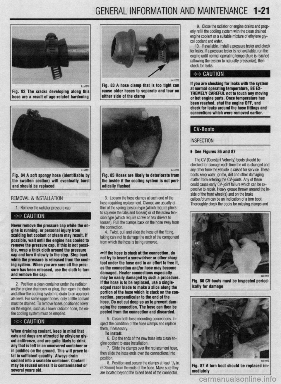
IWSIZXJ FM. 83 A hose clamn that is taa tiaht can
Fig. 82 The cracks developing along this
hose are a result of age-related hardening caise older hoses td separate and ‘iear on
either side of the clamp
lCCS1221 Fig. 84 A soft spongy hose (identifiable by
1 the swollen section) will eventually burst
and should be replaced
IEMOVAL &,INSTALLATION '
1. Remove the radiator pressure cap. her of the sorina tension tvoe (which reouire oliers
3 squeeze the 6bs and loosenj or of the’screw ten-
ion type (which require screw or hex drivers to
oosen). Pull the clamps back on the hose away from
he connection. Never remove the pressure cap while the en-
gine is running, or personal injury from
scalding hot coolant or steam may result. If
possible, wait until the engine has cooled to
remove the pressure cap. If this is not possi-
ble, wrap a thick cloth around the pressure
cap and turn it slowly to the stop. Step back
while the pressure is released from the cool-
ing system. When you are sure all the pres-
sure has been released, use the cloth to turn
and remove the cao.
2. Position a clean container under the radiator
and/or engine draincock or plug, then open the drain
and allow the cooling system to drain to an appropri-
ate level. For some upper hoses, only a little coolant
must be drained. To remove hoses positioned lower
on the engine, such as a lower radiator hose, the en-
tire cooling system must be emptied.
When draining coolant, keep in mind that
cats and dogs are attracted by ethylene gly-
col antifreeze, and are quite likely to drink
any that is left in an uncovered container or
in puddles on the ground. This will prove fa-
tal in sufficient quantity. Always drain
coolant into a sealable container. Coolant
may be reused unless it is contaminated or
several years old. 9. Close the radiator or engine drains and prop-
erly refill the cooling system with the clean drained
engine coolant or a suitable mixture of ethylene gly-
cot coolant and water.
10. If available, install a pressure tester and check
for leaks. If a pressure tester is not available, run the
engine until normal operating temperature is reached
(allowing the system to naturally pressurize), then
check for leaks.
If you are checking for leaks with the system
at normal operating temperature, BE EX-
TREMELY CAREFUL not to touch any moving
or hot engine parts. Once temperature has
been reached. shut the enaine OFF. and
Fig. 85 Hoses are likely to deteriorate from
the inside if the cooling system is not peri-
odically flushed check for leaks around the-hose fittings and
connections which were removed earlier.
INSPECTION
b See Figures 88 and 87
The CV (Constant Velocity) boots should be
checked for damage each time the oil is changed and
any other time the vehicle is raised for service. These
boots keep water, grime, dirt and other damaging
matter from entering the CV-joints. Any of these
could cause early CV-joint failure which can be ex-
pensive to repair. Heavy grease thrown around the in-
side of the front wheel(s) and on the brake
caliper/drum can be an indication of a torn boot.
Thorouahlv check the boots for missina clamos and 3. Loosen the hose clamps at each end of the
rose requiring replacement. Clamps are usually ei-
4. Twist, pull and slide the hose off the fitting,
sking care not to damage the neck of the component
rom which the hose is being removed.
*If the hose is stuck at the connection, do
lot try to insert a screwdriver or other sharp
ool under the hose end in an eff art to free it,
IS the connection and/or hose may become
lamaged. Heater connections especially
nay be easily damaged by such a procedure.
f the hose is to be replaced, use a single-
!dged razor blade to make a slice along the
lortion of the hose which is stuck on the con-
section, perpendicular to the end of the
lose. 00 not cut deep so as to prevent dam-
aging the connection. The hose can then be
keeled from the connection and discarded. Fig. 86 CV-boots must be inspected period-
5.. Clean both hose mounting connections. In-
,pect the condition of the hose clamps and replace
hem, if necessary.
To install:
6. Dip the ends of the new hose into clean en-
fine coolant to ease installation.
7. Slide the clamps over the replacement hose,
hen slide the hose ends over the connections into
rosition.
8. Position and secure the clamps at least l/d in.
6.35mm) from the ends of the hose. Make sure they
Ire located beyond the raised bead of the connector.
Page 23 of 408
l-24 GENERALINFORMATIONAND MAINTENANCE
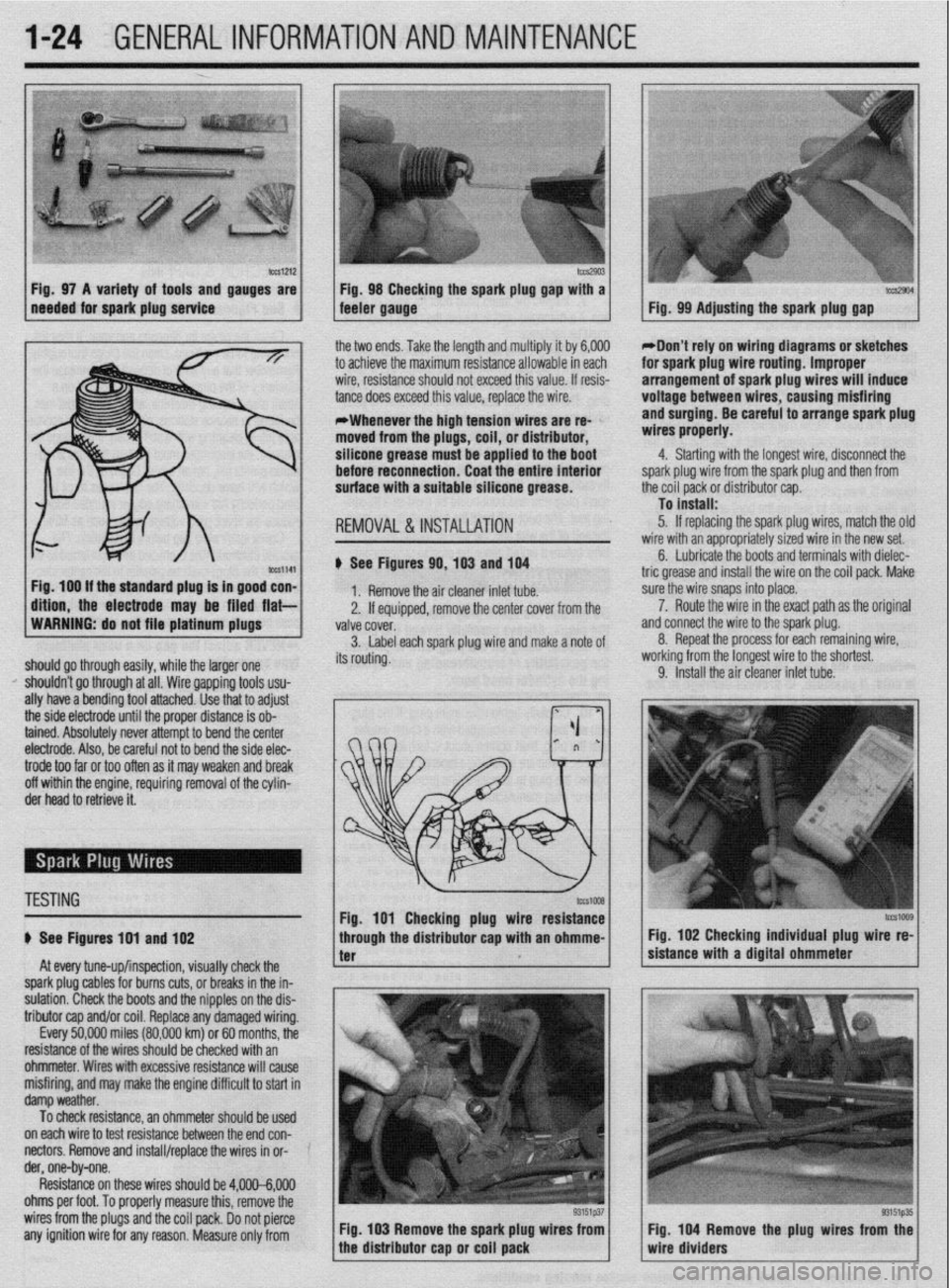
b%slZl2 Fig. 97 A variety of tools and gauges are
needed for spark plug service tm2903 Fig. 98 Checking the spark plug @au with a tccs2904 feeler gauge. - Fig. 99 Adjusting the spark plug gap
ig. 100 If the standard plug Is in good con-
ftlon, the electrode may be filed flat- the two ends. Take the length and multiply it by 6,000
to achieve the maximum resistance allowable in each
wire, resistance should not exceed this value. If resis-
tance does exceed this value, replace the wire.
*Whenever the high tension wires are re- ’
moved from the plugs, coil, or distributor,
silicone grease must be applied to the boot
before reconnection. Coat the entire Interior
surface with a suitable silicone grease.
REMOVAL &INSTALLATION
# See Figures 90,103 and 104
1. Remove the air cleaner inlet tube.
2. If eouiooed, remove the center cover from the
WARNING: do not file platinum plugs
valve covei.
3. Label each spark plug wire and make a note of
should go through easily, while the larger one its routing.
I’ shouldn’t go through at all. Wire gapping tools usu-
ally have a bending tool attached. Use that to adjust
the side electrode until the proper distance is ob-
tained. Absolutely never attempt to bend the center
electrode. Also, be careful not to bend the side elec- *Don’t rely on wiring diagrams or sketches
for spark plug wire routing. Improper
arrangement of spark plug wires will induce
voltage between wires, causing misfiring
and surging. Be careful to arrange spark plug
wires properly.
4. Starting with the longest wire, disconnect the
spark plug wire from the spark plug and then from
the coil pack or distributor cap.
To install:
5. If replacing the spark plug wires, match the olc
wire with an appropriately sized wire in the new set.
6. Lubricate the boots and terminals with dielec-
tric grease and install the wire on the coil pack. Make
sure the wire snaps into place.
a 7. Route the wire in the exact path as the original
nd connect the wire to the spark plug.
8. Repeat the process for each remaining wire,
iorking from the longest wire to the shortest.
9. Install the air cleaner inlet tube.
trode too far or too often as it may weaken and break
off within the engine, requiring removal of the cylin-
der head to retrieve it.
TESTING
# See Figures 191 and 102
At every tune-up/inspection, visually check the
spark plug cables for burns cuts, or breaks in the in-
sulation. Check the boots and the nipples on the dis-
tributor cap and/or coil. Replace any damaged wiring.
Every 50,000 miles (80,000 km) or 60 months, the
resistance of the wires should be checked with an
ohmmeter. Wires with excessive resistance will cause
misfiring, and may make the engine difficult to start in
damp weather.
To check resistance, an ohmmeter should be used ’
on each wire to test resistance between the end con-
nectors. Remove and install/replace the wires in or- ’
der, one-by-one.
Resistance on these wires should be 4,000-6,000
ohms per foot. To properly measure this, remove the
wires from the plugs and the coil pack. Do not pierce
any ignition wire for any reason. Measure only from Fig. 103 Remove the spark plug wires from
tcG1009 Fig. 102 Checking individual plug wire re-
sistance with a digital ohmmeter
Fig. 104 Remove the plug wires from the
wire dividers
Page 33 of 408
.
l-34 GENERALINFORMATIONAND MAINTENANCE
Engine oil level should be checked every time you
put fuel in the vehicle or are under the hood perform- miles of highway driving. Fluid which is warmed to
normal operating temperature will flow faster, drain
ing other maintenance.
1. Park the vehicle on a level surface.
2. The enaine mav be either hot or cold when
, if it is hot, wait a few min- checking oil level. The EPA warns that prolonged contact with
used engine oil may cause a num’ * * *
dianrAnrr inrldinn ranrnrl V#lll more completely and remove more contaminants
frnm tho clnnine
utes after the engine has been turned OFF to allow the
oil to drain back into the crankcase. If the engine is
cold, do not start it before checking the oil level. point on the oil pan. If not, you may have to raise the
vehicle slightly higher on one jackstand (side) than
3. Open the hood and locate the engine oil dip-
stick. Pull the dipstick from its tube, wipe it clean,
and reinsert it. Make sure the diDstick is fullv in-
serted.
4. Pull the dipstick from its tube again. Holding it to used engin
be worn whet
handsandan
so*m ..#a . . . . .
IDer 01 SKlll u,yu,u=,+, ,,,u,uu,,,u uu,,u=, i , vu should
uff art to minimize your exposure
le oil. Protective gloves should
1 changing the oil. Wash your
y other exposed skin areas as
111 aJ vv4ble after exposure to used en-
m nil St-mn mwl w&or nr umtarlncr hand gin Y “II. ““up “ll” .,U.“I, “rn W.Y.“. .““I .I....” cleaner should be used.
horizontally, read the oil level. The oilshould be be-
tween the MIN and MAX marks or the notches on the
dipstick. If the oil is below the MIN mark or lower
notch, add oil of the proper viscosity through the
capped opening of the valve cover. *The engine oil and oil filter should be
changed at the recommended intervals on
the Maintenance Chart. Though some manu-
facturers have at times recommended chang-
ing the filter only at every other oil change, ’
Chilton recommends that you always change
ll”,,, Cl>” ““y”‘“. 1. Raise and support the vehicle safely on jack-
stands. Make sure the oil drain olua is at the lowest
the other.
2. Before you crawl under the vehicle, take a look
at where you will be working and gather all the nec-
essary tools, such as a few wrenches or a ratchet and
strip of sockets, the drain pan, some clean rags and,
if the oil filter is more accessible from underneath the
vehicle, you will also want to grab a bottle of oil, the
new filter and a filter wrench at this time.
5. Reolace the diostick. and check the level aaain
. The benefit of fresh oil
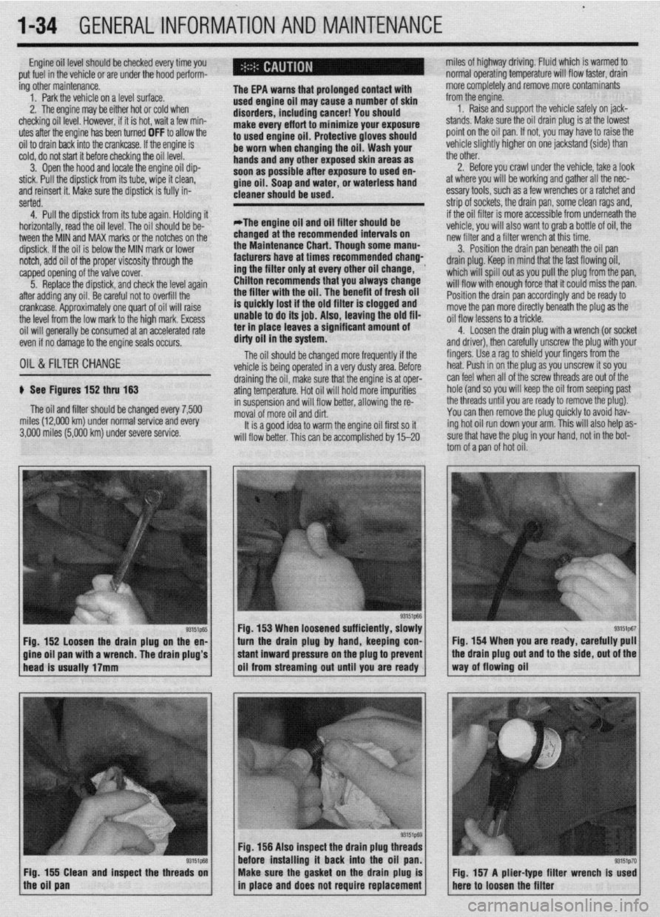
p See Figures 152 thru 153
The oil and filter should be changed every 7,500
miles (12,000 km) under normal service and every
3,000 miles (5,000 km) under severe service.
93151p-55 Fig. 152 loosen the drain plug on the en-
a wrench. The drain plug’s 3. Position the drain pan beneath the oil pan
drain plug. Keep in mind that the fast flowing oil,
which will spill out as you pull the plug from the pan,
will flow with enough force that it could miss the pan.
Position the drain pan accordingly and be ready to
move the pan more directly beneath the plug as the
oil flow lessens to a trickle.
4. Loosen the drain ~lua with a wrench (or socket
and driver), then carefuliy unscrew the plug with your
fingers. Use a rag to shield your fingers from the
heat. Push in on the plug as you unscrew it so you
draining the oil, make sure that the engine is at oper- can feel when all of the screw threads are out of the
ating temperature. Hot oil will hold more impurities hole (and so you will keep the oil from seeping past
in suspension and will flow better, allowing the re- the threads until you are ready to remove the plug).
moval of more oil and dirt. You can then remove the plug quickly to avoid hav-
It is a good idea to warm the engine oil first so it ing hot oil run down your arm. This will also help as-
will flow better. This can be accomolished bv 15-20 sure that have the plug in your hand, not in the bot-
tom of a pan of hot oil.
Fig. 153 When loosened sufficiently, slowly
turn the drain plug by hand, keeping con- Fig. 154 When you are ready, carefully pull
Fig. 156 Also inspect the drain plug th
before installing it back into the oil
Fig. 155 Clean and inspect the threads on
the oil pan Make sure the gasket on the drain plug is
in place and does not require replacement Fig. 157 A plier-type filter wrench Is used
here to loosen the filter
Page 34 of 408
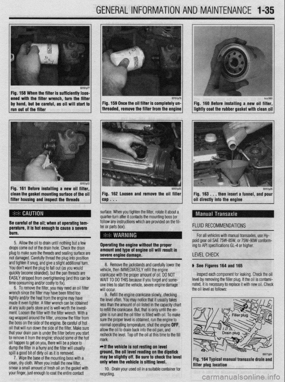
GENERALINFORMATIONAND MAINTENANCE l-35
Fig. 158 When the filter is sufficiently loos-
Fig. 181 Before installing a new oil filter,
clean the gasket mounting surface of the oil
filter housing and inspect the threads Fig. 182 Loosen and remove the oil filler
cap . . .
surface. When you tighten the filter, rotate it about a
quarter-turn after it contacts the mounting boss (or Fig. 183 . , , then insert a funnel, and pour
oil directly into the engine
follow any instructions
which are provided on the fil-
ter or parts box).
Operating the engine without the proper
amount and type of engine oil will result In
severe engtne damage. FLUID RECOMMENDATIONS
For all vehicles with manual transaxles, use Hy-
poid gear oil SAE 75W-85W, or 75W-9OW conform-
ing to API specifications GL-4 or higher.
LEVELCHECK Be careful of the oil; when at operating tem-
perature, it is hot enough to cause a severe
bum.
5. Allow the oil to drain until nothing but a few
drops come out of the drain hole. Check the drain
plug to make sure the threads and sealing surface are
not damaged. Carefully thread the plug into position
and tighten it snug, and give a slight additional turn.
You don’t want the plug to fall out (as you would
quickly become stranded), but the pan threads are
EASILY stripped from overtightening (and this can be
time consuming and/or costly to fix).
6. To remove the filter, you may need an oil filter
wrench since the filter may have been fitted too
tightly and/or the heat from the engine may have
made it even tighter. A filter wrench can be obtained
at any auto parts store and is well-worth the invest-
ment. Loosen the filter with the filter wrench. With a
rag wrapped around the filter, unscrew the filter from
the boss on the side of the engine. Be careful of hot
oil that will run down the side of the filter. Make sure
that your drain pan is under the filter before you start
to remove it from the engine; should some of the hot
oil happen to get on you, there will be a place to
dump the filter in a hurry and the filter will usually
spill a good bit of dirty oil as it is removed.
7. Wipe the base of the mounting boss with a
clean, dry cloth. When you install the new filter,
smear a small amount of fresh oil on the gasket with
your finger, just enough to coat the entire contact 8. Remove the jackstands and carefully lower the
vehicle, then IMMEDIATELY refill the engine
crankcase with the proper amount of oil. DO NOT
WAIT TO DO THIS because if you forget and some-
one tries to start the vehicle, severe engine damage
will occur.
9. Refill the engine crankcase slowly, checking
the level oflen, you may r..‘:-- U.-1 :L ..-..” II.. .-L-e
lVL,VY II,UL II UUUU,,J ,“,\U.J
less than the amount of oil listed in the capacity chart
to refill the crankcase. But, that is only until the en-
gine is run and the oil filter is filled with oil. To make
sure the proper level is obtained, run the engine to
normal operating temperature, shut the engine OFF,
allow the oil to drain back into the oil pan, and
recheck the level. Top off the oil at this time to the fill
mark.
*If the vehicle Is not resting on level
ground, the oil level reading on the dipstick
may be slightly off. Be sure to check the level
only when the vehicle is sitting level.
10. Drain your used oil in a suitable container for
recycling. b See Flgures 184 and 185
Inspect each component for leaking. Check the oil
level by removing the filler plug. If the oil is contami-
nated, it is necessary to replace it with new oil. Check
the oil level as follows:
89571gM Fig. 164 Typtcal manual transaxle drain and
filler plug location
Page 35 of 408
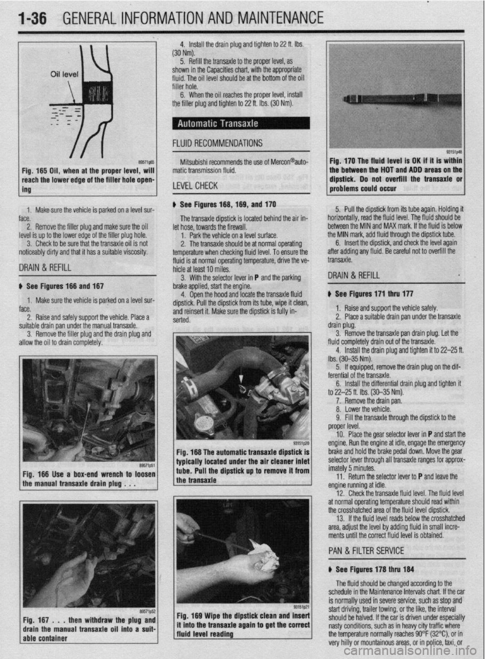
.
l-36 GENERALINFORMATIONAND MAINTENANCE
Install the drain plug and tighten to 22 ft. Ibs.
(304Nm)
5. Refill the transaxle to the proper level, as
shown in the Capacities chart, with the appropriate
fluid. The oil level should be at the bottom of the oil
filler hole. I
6. When the oil reaches the orooer level, install
the filler plug and tighten to 22 ft. Ibs. (30 Nm).
FLUID RECOMMENDATIONS
8957i565 Fig, 165 Oil, when at the proper level, will
reach the lower edge of tC=+ frfr*r u*rn -non-
ing Mitsubishi recommends the use of Mercon@auto-
matic transmission fluid.
LEVELCHECK
Fig. 170 The fluid level is OK if it is within
the between the HOT and ADD areas on the
&&i& Do not overfill the transaxle or
-.*".."... -- .*"- problems could o ccur
1. Makesure the vehicle is oarked on a level sur-
face.
2. Remove the filler plug and make sure the oil
level is up to the lower edge of the filler plug hole.
3. Check to be sure that the transaxle oil is not
noticeably dirty and that it has a suitable viscosity. u See Figures 168,169, and 170
fluid is at normal operating temperature, drive the ve- The transaxle dipstick is located behind the air in-
hicle at least 10 miles. let hose, towards the firewall.
1. Park the vehicle on a level surface.
2. The transaxle should be at normal operating
temperature when checking fluid level. To ensure the 5. Pull the dipstick from its tube again. Holding it
horizontally, road the fluid level. The fkrid should be
between the MIN and MAX mark. If the fluid is below
the MIN mark, add fluid through the dipstick tube.
DRAIN & REFILL
6. Insert the dipstick, and check the level again
after adding any fluid. Be careful not to overfill the
transaxle.
3. With the selector lever in P and the parking
DRAIN & REFILL u See Figures 166 and 167
1. Make sure the vehicle is parked on a level sur-
face.
2. Raise and safely support the vehicle. Place a brake applied, start the engine.
4. Open the hood and locate the transaxle fluid
dipstick. Pull the dipstick from its tube, wipe it clean,
and reinsert it. Make sure the dipstick is fully in-
serted.
suitable drain pan under the manual transaxle.
3. Remove the filler plug and the drain plug and
allow the oil to drain completely.
Fig. 166 The automatic transaxle dipstick is
typically located under the air cleaner inlet
Fig. 166 Use a box-end wrench to loosen
the manual transaxle drain plug . . . tube. Pull the dipstick up to remove it from
the transaxle
Fig. 169 Wipe the dipstick clean and Insert
/fluid level reading ., it mto the transaxle agam to get the correct
j The fluid should be changed according to the
schedule in the Maintenance Intervals chart. If the car
is normally used in severe service, such as stop and
start driving, trailer towing, or the like, the interval
should be halved. If the car is driven under especially
nasty conditions, such as in heavy city traffic where
the temperature normally reaches 90°F (32%), or in
very hilly or mountainous areas, or in police, taxi, or b See Figures 171 thru 177
1. Raise and support the vehicle safely.
2. Place a suitable drain pan under the transaxle
drain plug.
3. Remove the transaxle pan drain plug. Let the
fluid completely drain out of the transaxle.
4. Install the drain plug and tighten it to 22-25 ft.
lbs. (30-35 Nm).
5. If equipped, remove the drain plug on the dif-
ferential of the transaxle.
6. Install the differential drain plug and tighten ft
to 22-25 ft. Ibs. (30-35 Nm).
7. Remove the drain pan.
8. Lower the vehicle.
9. Fill the transaxle through the dipstick to the
proper level.
10. Place the gear selector lever in P and start the
engine. Run the engine at idle, engage the emergency
brake and hold the brake pedal down. Move the gear
selector lever through all transaxle ranges for approx-
imately 5 minutes.
11. Return the selector lever to P and leave the
engine running at idle.
12. Check the transaxle fluid level. The fluid level
at normal operating temperature should read within
the crosshatched area of the fluid level dipstick.
13. If the fluid level reads below the crosshatched
area, adjust the level by adding fluid in small incre-
ments until the correct fluid level is obtained.
PAN &FILTER SERVICE
b See Figures 178 thru 184
Page 36 of 408
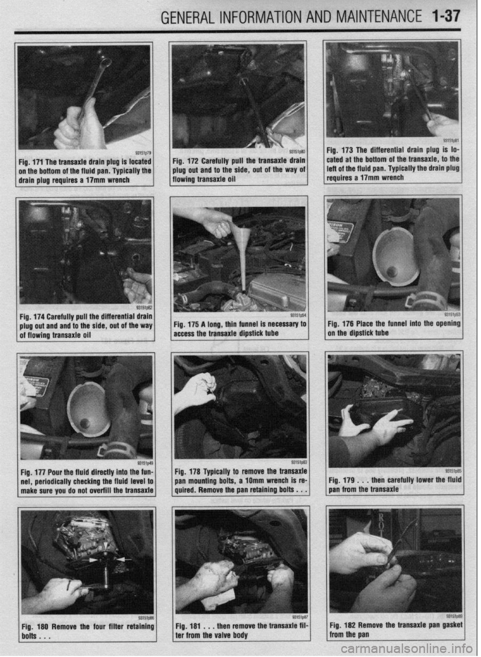
_. .I ..-.
-._.
GENERALINFORMATIONAND MAINTENANCE l-37
Fig. 172 Carefully pull the transaxie drain
plug out and to the side, out of the way oi
flowing transaxie oil Fig. 173 The differential drain plug is lo-
cated at the bottom of the transaxie, to the
left of the fluid pan. Typically the drain plug
reauires a 17mm wrench
periodically checking the fluid level to
make sure you do not overfill the transaxle pan mounting
bolts, a 1Omm wrench is re-
Fig. 179 . . , then carefully lower the fluid
quired. Remove the pan retaining bolts . . . pan from the transaxle
Fig, 181 . , . then remove the transaxie film
ter from the valve body Fig. 182 Remove the transaxie pan
gasket from the pan
Page 39 of 408
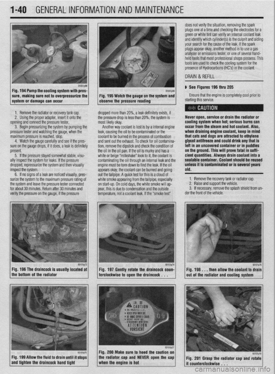
l-40 GENERALINFORMATIONAND MAINTENANCE
aiffiip98 Fig. 194 Pump the cooling system with pres-
sure, making sure not to overpressurize the
1 system or damage can occur
1. Remove the radiator or recovery tank cap.
2. Using the proper adapter, insert it onto the
opening and connect the pressure tester,
3. Begin pressurizing the system by pumping the
pressure tester and watching the gauge, when the
maximum pressure is reached, stop.
4. Watch the gauge carefully and see if the pres-
sure on the gauge drops, if it does, a leak is definitely
present.
5. If the pressure stayed somewhat stable, visu-
ally inspect the system for leaks, If the pressure
dropped, repressurize the system and then visually
inspect the system.
,
/ observe the pressure reading “@‘p~ 1 Fig 195 Watch the gauge on the system and
dropped more than 20%, a leak definitely exists, if
the oressure droo is less than 20%. the svstem is
most likely okay:
, cooling system when hot; serious burns can
Another way coolant is lost is by a internal engine occur from the steam and hot coolant. Also,
leak, causing the oil to be contaminated or the when draining engine coolant, keep in mind
coolant to be burned in the process of combustion that cats and dogs are attracted to ethylene
and sent out the exhaust. To check for oil contamina- glyeol antifreeze and could drink any that is
tion, remove the dipstick and check the condition of left in an uncovered container or in puddles
the oil in the oil pan. If the oil is murky and has a on the ground. This will prove fatal in suffi-
white or beige “milkshake” look to it, the coolant is cient quantities. Always drain coolant into a
contaminating the oil through an internal leak and the sealable container. Coolant should be reuser
enqine must be torn down to find the leak. If the oil mless it is contaminated or is several years
6. If no signs of a leak are noticed visually, pres-
surize the system to the maximum pressure rating of
the system and leave the uressure tester connected
fl sr about 30 minutes. Return after 30 minutes and
V erify the pressure on the gauge, if the pressure does not verify the situation, removing the spark
plugs one at a time and checking the electrodes for a
green or white tint can verify an internal coolant leak
and identify which cylinder(s) is the culprit and aiding
your search for the cause of the leak. If the spark
plugs appear okay, another method is to use a gas
analyzer or emissions tester, or one of several hand-
held tools that most professional shops possess. This
tools are used to check the cooling system for the
presence of Hydrocarbons (HC’s) in the coolant.
DRAIN & REFILL
p See figures 196 thru 205
Ensure that the engine is completely cool prior to
starting this service.
Never open, service or drain the radiator or
Ippears okay, the coolant can be burned and going
jut the tailpipe. A quick test for this is a cloud of
Nhite smoke appearing from the tailpipe, especially
In start-up. On cold days, the white smoke will ap-
Iear, this is due to condensation and the outside
emperature, not a coolant leak. If the “smoke test”
Fig. 196 The draincock is usually located at
Fig. 197 Gently rotate the draincock coun-
the bottom of the radiator
terclockwise to open the draincock . . .
Fig. 199 Allow the fluid to drain until it stops
and tighten the draineock hand tight
93151p27
1. Remove the recovery tank or radiator cap.
2, Raise and support the vehicle.
3. If necessary, remove the splash shield from un
ler the front of the vehicle.
93im76 Fig, 198 . _ . then allow the coolant to drain
out of the radiator and cooling system
Fig. 200 Make sure to heed the caution on
the radiator cap and NEVER open the cap
1 when the engine is hot ,, Fig. 201 Grasp the radiator cap and rotate
it counterclockwise . . .