1900 MITSUBISHI DIAMANTE trunk
[x] Cancel search: trunkPage 31 of 408
.
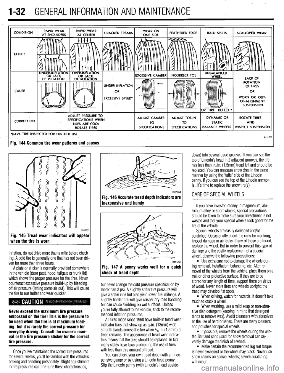
1-32 GENERALINFORMATIONAND MAINTENANCE
CONDITION
EFFECT
CAUSE
CORRECTION UNDER-INFLATION
EXCESSIVE SPEED’ WORN OR OUT-
OF-ALIGNMENT
ADJUST PRESSURE TO
SPECIFICATIONS WHEN
TIRES ARE COOL
ROTATE TIRES
/ BALANCE WHEELS INSPECT SUSPENSION
HAVE TIRE INSPECTED FOR FURTHER USE.
lCCSi267 ig. 144 Common tire wear patterns and causes
1~~~1265 Fig. 145 Tread wear indicators will appear
when the tire is worn
inflation, do not drive more than a mile before check-
ing. A cold tire is generally one that has not been dri-
ven for more than three hours.
A plate or sticker is normally provided somewhere
in the vehicle (door post, hood, tailgate or trunk lid)
which shows the proper pressure for the tires. Never
counteract excessive pressure build-up by bleeding
off air pressure (letting some air out). This will cause
the tire to run hotter and wear quicker.
Never exceed the maximum tire pressure
embossed on the tire! This is the pressure to
be used when the tire is at maximum load-
ing, but it is rarely the correct pressure for
everyday driving. Consult the owner’s man-
ual or the tire pressure sticker for the correct
tire pressure.
Once you’ve maintained the correct tire pressures
for several weeks, you’ll be familiar with the vehicle’s
braking and handling personality. Slight adjustments
in tire pressures can fine-tune these characteristics,
1~~~1264 Fig. 146 Accurate tread depth indicators are
inexuensive and handv
Fig. 147 A penny works well for a quick
check of tread death
but never change the cold pressure specification by
more than 2 psi. A slightly softer tire pressure will
give a softer ride but also yield lower fuel mileage. A
slightly harder tire will give crisper dry road handling
but can cause skidding on wet surfaces. Unless
you’re fully attuned to the vehicle, stick to the recom-
mended inflation pressures.
All tires made since 1968 have built-in tread wear
indicator bars that show up as j/2 in. (13mm) wide
smooth bands across the bre when V,~ in. (1.5mm) of
tread remains. The appearance of tread wear indica-
tors means that the tires should be replaced. In fact,
many states have laws prohibiting the use of tires
with less than this amount of tread.
You can check your own tread depth with an inex-
pensive gauge or by using a Lincoln head penny.
Shp the Lrncoln penny (with Lincoln’s head upside- down) into several tread grooves. If you can see the
top of Lincoln’s head in 2 adjacent grooves, the tire
has less than V,~ in. (1.5mm) tread left and should be
replaced. You can measure snow tires in the same
manner by using the “tails” side of the Lincoln
penny. If you can see the top of the Lincoln memor-
ial, its time to replace the snow tire(s).
CAREOFSPECIALWHEELS
If you have invested money in magnesium, alu-
minum alloy or sport wheels, special precautions
should be taken to make sure your investment is not
wasted and that your special wheels look good for the
life of the vehicle.
Special wheels are easily damaged and/or
scratched. Occasionally check the rims for cracking,
impact damage or air leaks. If any of these are found,
replace the wheel. But in order to prevent this type of
damage and the costly replacement of a special
wheel, observe the following precautions:
l Use extra care not to damage the wheels dur-
ing removal, installation, balancing, etc. After re-
moval of the wheels from the vehicle, place them on a
mat or other protective surface. If they are to be
stored for any length of time, support them on strips
of wood. Never store tires and wheels upright; the
tread may develop flat spots.
l When driving, watch for hazards; it doesn’t take
much to crack a wheel.
l When washing, use a mild soap or non-abra-
sive dish detergent (keeping in mind that detergent
tends to remove wax). Avoid cleansers with abrasives
or the use of hard brushes. There are many cleaners
and polishes for special wheels.
l If possrble, remove the wheels during the win-
ter. Salt and sand used for snow removal can se-
verely damage the finish of a wheel.
l Make certain the recommended lug nut torque
is never exceeded or the wheel may crack. Never use
snow chains on special wheels; severe scratching
will occur.
Page 45 of 408
.
I-46 GENERALINFORMATIONAND MAINTENANCE
2. Pull the jumping vehicle (with the good bat-
tery) into a position so the jumper cables can reach
the dead battery and that vehicle’s engine. Make sure
that the vehicles do NOT touch.
3. Place the transmissions/transaxles of both ve-
hicles in Neutral (MT) or P (AT), as applicable, then
firmly set their parking brakes.
*ff necessary for safety reasons, the hazard
lights on both vehicles may be operated
throughout the entire procedure without sig-
nificantiy increasing the diff icuity of jumping
the dead battery.
4. Turn all lights and accessories OFF on both
vehicles. Make sure the ignition switches on both ve-
hicles are turned to the OFF position.
5. Cover the battery cell caps with a rag, but do
not cover the terminals.
6. Make sure the terminals on both batteries are
clean and free of corrosion or proper electrical con-
nection will be impeded. If necessary, clean the bat-
tery terminals before proceeding.
7. Identify the positive (+) and negative (-) termi-
nals on both batteries.
8. Connect the first jumper cable to the positive
(t) terminal of the dead battery, then connect the
other end of that cable to the positive (t) terminal of
the booster (good) battery.
9. Connect one end of the other jumper cable to
the negative (−) terminal on the booster bat-
tery and the final cable clamp to an engine bolt head,
alternator bracket or other solid, metallic point on the
engine with the dead battery. Try to pick a ground on
the engine that is positioned away from the battery in
order to minimize the possibility of the 2 clamps
touching should one loosen during the procedure.
DO NOT connect this clamp to the negative (-) termi-
nal of the bad battery. cable on the donor battery. Disconnect the positive
cable from the donor battery and finally, disconnect
the positive cable from the formerly dead battery. Be
careful when disconnecting the cables from the posi-
tive terminals not to allow the alligator clips to touch
any metal on either vehicle or a short and sparks will
occur.
I
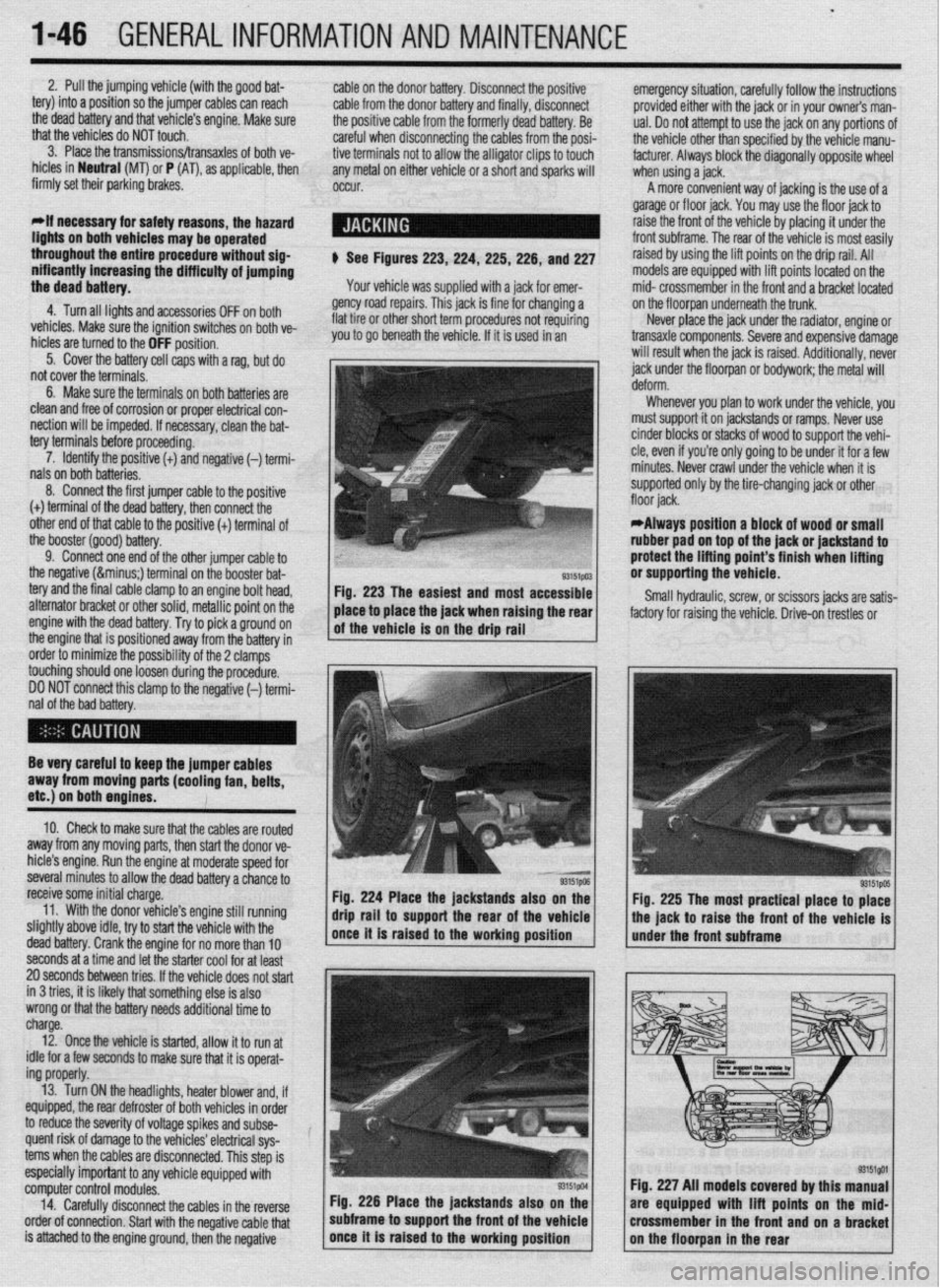
$ See Figures 223,224, 225,226, and 227
Your vehicle was supplied with a jack for emer-
gency road repairs. This jack is fine for changing a
flat tire or other short term procedures not requiring
you to go beneath the vehicle. If it is used in an emergency situation, carefully follow the instructions
provided either with the jack or in your owners man-
ual. Do not attempt to use the jack on any portions of
the vehicle other than specified by the vehicle manu-
facturer. Always block the diagonally opposite wheel
when using a jack.
A more convenient way of jacking is the use of a
garage or floor jack. You may use the floor jack to
raise the front of the vehicle by placing it under the
front subframe. The rear of the vehicle is most easily
raised by using the lift points on the drip rail. All
models are equipped with lift points located on the
mid- crossmember in the front and a bracket located
on the floorpan underneath the trunk.
Never place the jack under the radiator, engine or
transaxle components. Severe and expensive damage
will result when the jack is raised. Additionally, never
jack under the floorpan or
bodywork; the
metal will
Whenever you plan to work under the vehicle, you
must support it on jackstands or ramps. Never use
cinder blocks or stacks of wood to support the vehi-
cle, even if you’re only going to be under it for a few
minutes. Never crawl under the vehicle when it is
supported only by the tire-changing jack or other
*Always position a block of wood or small
rubber pad on top of the jack or jackstand to
protect the lifting point’s finish when lifting
or supporting the vehicle.
Small hydraulic, screw, or scissors jacks are satis-
factory for raising the vehicle. Drive-on trestles or
Be very careful to keep the jumper cables
away from moving parts (cooling fan, belts,
etc.) on both engines.
10. Check to make sure that the cables are routed
away from any moving parts, then start the donor ve-
hicle’s engine. Run the engine at moderate speed for
several minutes to allow the dead battery a chance to
receive some initial charge.
11. With the donor vehicle’s engine still running
slightly above idle, try to start the vehicle with the
dead battery. Crank the engine for no more than 10 &stands also on the
Fig. 225 The most practical place to place
front of the vehicle is
seconds at a time and let the starter cool for at least
20 seconds between tries. If the vehicle does not start
in 3 tries, it is likely thatsomething else is also
wrong or that the battery needs additional time to
charge.
12. Once the vehicle is started, allow it to run at
idle for a few seconds to make sure that it is operat-
ing properly.
13. Turn ON the headlights, heater blower and, if
equipped, the rear defroster of both vehicles in order
to reduce the severity of voltage spikes and subse-
quent risk of damage to the vehicles’ electrical sys-
tems when the cables are disconnected. This step is
especially important to any vehicle equipped with
computer control modules.
14. Carefully disconnect the cables in the’reverse
order of connection. Start with the negative cable that
is attached to the engine ground, then the negative Fig. 226 Place the jackstands also
subframe to support the front of the Fig. 227 All models covered by this
are equipped with lift points on t
crossmember in the front and on a
Page 190 of 408
FUELSYSTEM 513
l Always replace worn fuel fitting O-rings with
new. Do not substitute fuel hose or equivalent, where
I
The Multi-Point Injection (MPI) system is electroni-
rally controlled by the Engine Control Module (ECM),
based on data from various sensors. The ECM controls
the fuel flow, idle speed and ignition timing. fuel pipe is installed.
Fuel is supplied to the injectors by an electric in-
tank fuel pump and is distributed to the respective in-
jectors via the main fuel pipe. The fuel pressure ap-
plied to the injector is constant and higher than the
pressure in the intake manifold. The pressure is con-
trolled by the fuel pressure regulator. The excess fuel
is returned to the fuel tank through the fuel return pipe.
When an electric current flows in the injector, the
injector valve is fully opened to supply fuel. Since the
fuel pressure is constant, the amount of the fuel in-
jetted from the injector into the manifold is increased
or decreased in proportion to the time the electric
current flows. Based on ECU signals, the injectors in-
ject fuel to the cylinder manifold ports in firing order. Fuel injection systems remain under pres-
sure after the engine has been turned OFF.
Properly relieve fuel pressure before discon-
neeting any fuel lines. Failure to do so may
result in fire or personal injury.
1. Turn the ignition to the OFF position.
2. Loosen the fuel filler cap to release fuel tank
pressure.
I
The flow rate of the air drawn through the air
cleaner is measured by the air flow sensor. The air
enters the air intake plenum or manifold through the
throttle body. In the intake manifold, the air is mixed
with the fuel from the injectors and is drawn into the
cylinder, The air flow rate is controlled according to
the degree of the throttle valve and the servo motor
openings. The system is monitored through a num-
ber of sensors which feed information on engine con-
ditions and requirements to the ECM. The ECM cal-
culates the injection time and rate according to the
signals from the sensors,
Safety is the most important factor when perform-
ing not only fuel system maintenance but any type of
maintenance. Failure to conduct maintenance and re-
pairs in a safe manner may result in serious personal
injury or death. Maintenance and testing of the vehi-
cle’s fuel system components can be accomplished
safely and effectively by adhering to the following
rules and guidelines.
l To avoid the possibility of fire and personal in-
jury, always disconnect the negative battery cable un-
less the repair or test procedure requires that battery
voltage be applied.
l Always relieve the fuel system pressure prior to
disconnecting any fuel system component (injector,
fuel rail, pressure regulator, etc.), fitting or fuel line
connection. Exercise extreme caution whenever re- Observe all applicable safety precautions
when working around fuel. Whenever servic-
ing the fuel system, always work in a well
ventilated area. Do not allow fuel spray or va-
pors to come in contact with a spark or open
flame. Keep a dry chemical fire extinguisher
near the work area. Always keep fuel in a con-
tainer specifically designed for fuel storage;
also, always properly seal fuel containers to
avoid the possibility of fire or explosion.
3. For the Mirage, Diamante, and 1994-00
Galant, remove the rear seat cushion, then remove
the service cover and detach the fuel pump harness
connector.
4. For the 1990-93 FWD Galant, detach the fuel
pump harness connector located in the area of the
fuel tank. It may be necessary to raise the vehicle to
access the connector.
5. For the 1990-93 AWD Galant, remove the car-
pet from the trunk, locate the fuel tank wiring at the
pump access cover, then detach the wiring.
6. Start the vehicle and allow it to run until it
stalls from lack of fuel. Turn the key to the OFF posi-
tion.
7. Disconnect the negative battery cable, then at-
tach the fuel pump connector. Install the access .
cover, cushion or carpet as necessary.
8. Wrap shop towels around the fitting that is be-
ing disconnected to absorb residual fuel in the lines.
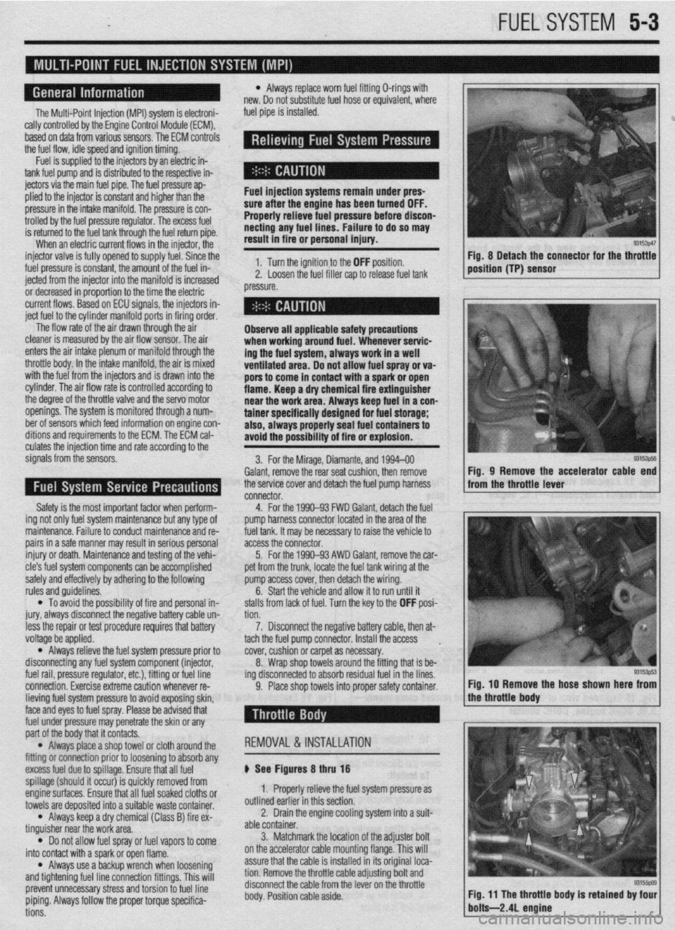
9. Place shop towels into proper safety container. Fig, 8 Detach the connector for the throttle
position (TP) sensor
93153ps5 Fig, 9 Remove the accelerator cable end
from the throttle lever
Fig. IO Remove the hose shown here from
lieving fuel system pressure to avoid exposing skin,
face and eyes to fuel spray. Please be advised that
fuel under pressure may penetrate the skin or any
part of the body that it contacts.
l Always place a shop towel or cloth around the
fitting or connection prior to loosening to absorb any
excess fuel due to spillage. Ensure that all fuel
spillage (should it occur) is quickly removed from
enginesurfaces. Ensure that all fuel soaked cloths or
towels are deposited into a suitable waste container.
l Always keep a dry chemical (Class B) fire ex-
tinguisher near the work area.
l Do not allow fuel spray or fuel vapors to come
into contact with a spark or open flame.
l Always use a backup wrench when loosening’
and tightening fuel line connection fittings. This will
prevent unnecessary stress and torsion to fuel line
piping. Always follow the proper torque specifica-
tions. REMOVAL &INSTALLATION
p See Figures 8 thru 18
1. Properly relieve the fuel system pressure as
outlined earlier in this section.
2. Drain the engine cooling system into a suit-
able container.
3. Matchmark the jocation of the adjuster bolt
on the accelerator cable mounting flange. This will
assure that the cable is installed in its original loca-
tion. Remove the throttle cable adjusting bolt and
disconnect the cable from the lever on the throttle
body. Position cable aside.
Page 217 of 408
6-14 CHASSIS ELECTRICAL
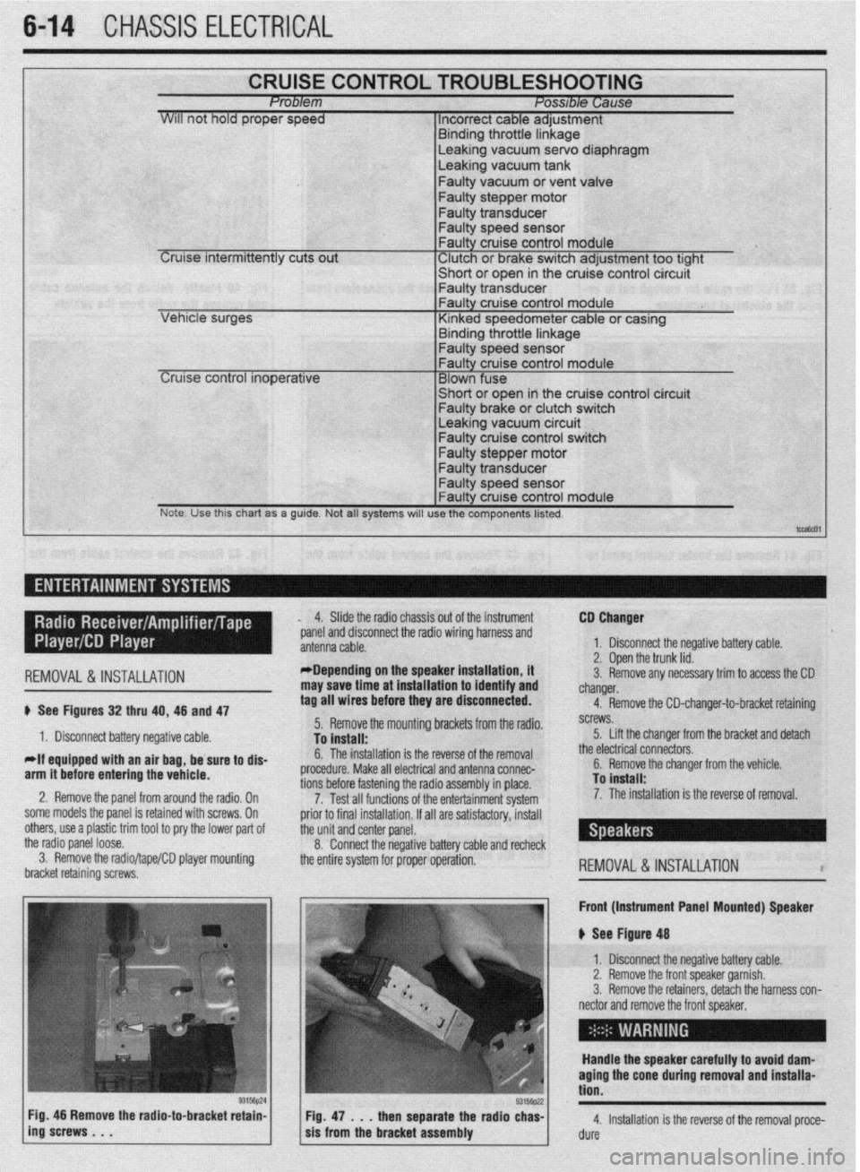
CRUISE CONTROL TROUBLESHOOTING Problem Posable Cause
WIII not hold proper speed 1 Incorrect cable adjustment
F.~. _I.~_ - 1L .-AL‘- I. I -
Cruise intermittently cuts out
trrnarng Inrome nnKage Leaking vacuum servo diaphragm
Leaking vacuum tank
Faulty vacuum or vent valve
Faulty stepper motor
Faulty transducer
Faulty speed sensor
Faulty cruise control module
‘ Clutch or brake switch adjustment too tight -chnrt *r nna* in the cruise control circuit
cer VI I”, . vt “y”‘,
I- Faulty transdu
Leaking vacuum circuit Faulty cruise control switch
Faulty stepper motor
Note. Use this chart as a guide. Not all systems will use the components listed.
t-,
I ,-- ,
REMOVAL&INSTALLATION
# See Figures 32 thru 40, 46 and 47
1. Disconnect battery negative cable.
*If equipped with an air bag, be sure to dis-
arm it before entering the vehicle.
2. Remove the panel from around the radio, On
some models the panel is retained with screws, On
others, use a plastic trim tool to pry the lower pad of
the radio panel loose.
3. Remove the radio/tape/CD player mounting
bracket retaining screws, 4. Slide the radio chassis out of the instrument
*panel and disconnect the radio wiring harness and
*Depending on the speaker installation, it
may save time at installation to identify and
tag all wires before they are disconnected.
5. Remove the mounting brackets from the radio.
To install:
6. The installation is the reverse of the removal
procedure. Make all electrical and antenna connec-
tions before fastening the radio assembly in place.
7. Test all functions of the entertainment system
prior to final installation. If all are satisfactory, install
the unit and center panel.
8. Connect the negative battery cable and recheck
the entire system for proper operation. CD Changer
1. Disconnect the negative battery cable.
2. Open the trunk lid.
3. Remove any necessary trim to access the CD
changer.
4. Remove the CD-changer-to-bracket retaining
screws.
5. Lift the changer from the bracket and detach
the electrical connectors.
6. Remove the changer from the vehicle.
To install:
7. The installation is the reverse of removal.
REMOVAL&INSTALLATION l
Front (Instrument Panel Mounted) Speaker
u See Figure 48
1. Disconnect the negative battery cable.
2. Remove the front speaker garnish.
3. Remove the retainers, detach the harness con-
nector and remove the front speaker,
Handle the speaker carefully to avoid dam-
aging the cone during removal and installa-
tion.
4. Installation is the reverse of the removal proce-
dure
Page 225 of 408
6-22 CHASSIS ELECTRICAL
b
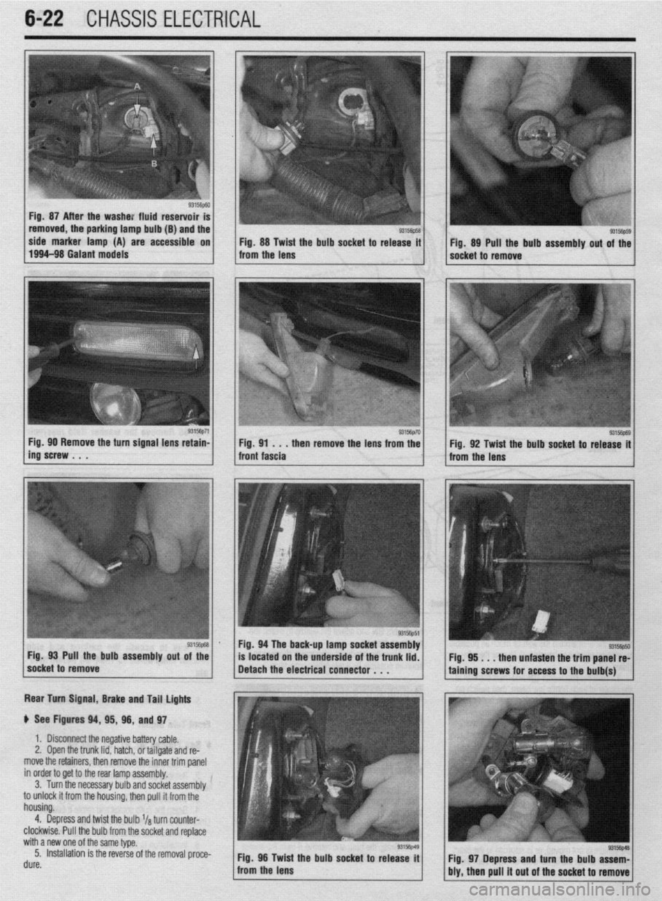
Fig. 87 After the washe: fluid reservoir
removed, the parking lamp bulb (B) and the
side marker lamp (A) are accessible on
Fig. 88 Twist the bulb socket to release it
1994-98 Galant models
from the lens Fig. 89 Pull the bulb assembly out of the
socket to remove
g3156p71 / Fig 90 Remove the turn signal lens retain-
ing’screw . . . . then remove the lens from the
Rear Turn Signal, Brake and Tail lights
p See Figures 94, 95, 96, and 97.
1. Disconnect the negative battery cable.
2, Open the trunk lid, hatch, or tailgate and re-
move the retainers, then remove the inner trim panel
in order to get to the rear lamp assembly.
3. Turn the necessary bulb and socket assembly
to unlock it from the housing, then pull it from the
housing.
4. Depress and twist the bulb l/a turn counter-
clockwise. Pull the bulb from the socket and replace
with a new one of the same type.
5. Installation is the reverse of the removal proce-
rl. ._^
UUIt?. Fig. 96 Twid
: the bulb socket to release it
from the lens
93156p69 Fig. 92 Twist the bulb socket to release it
from the lens
I
Fig. 94 The back-up lamp socket assembly
Pull the bulb assembly
out of the
located on the underside of the trunk lid.
. . . then unfasten the trim panel re-
Fig. 97 Depress and turn the bulb assem-
bly, then pull it out of the socket to remove
Page 226 of 408
![MITSUBISHI DIAMANTE 1900 Repair Manual CHASSIS ELECTRlCiL 6-23
93156P57 Fig. 98 The back-up lamp socket assembly Fig. 99 Twist the bulb socket to release the
is located on the underside of the trunk lid locking tabs from the lens *1W5y] MITSUBISHI DIAMANTE 1900 Repair Manual CHASSIS ELECTRlCiL 6-23
93156P57 Fig. 98 The back-up lamp socket assembly Fig. 99 Twist the bulb socket to release the
is located on the underside of the trunk lid locking tabs from the lens *1W5y]](/manual-img/19/57096/w960_57096-225.png)
CHASSIS ELECTRlCiL 6-23
93156P57 Fig. 98 The back-up lamp socket assembly Fig. 99 Twist the bulb socket to release the
is located on the underside of the trunk lid locking tabs from the lens *1W5y] Fig 100 Pull the bulb assembly straight out
of the socket to remove it
Back-up light
u See Figures 98, 99, and 100
1 I Disconnect the negative battery cable.
2. Open the trunk lid.
3. If equipped, remove the trim on the underside
of the trunk lid.
4. Turn the socket counterclockwise ‘14 of a turn
to release it from the lens.
5. Pull the bulb out to remove it from the socket,
6. The installation is the reverse of removal.
7. Connect the negative battery cable.
8. Verify the operation of the lamp.
Side Marker light
# See Figures 101, lOi, 103, and 104 I. Remove the two retaining screws from the 2. Open the trunk lid and detach the electrical
lens. connector from the lamp assembly.
2. Remove the lens from the rear fascia. 3. Remove the retaining screw holding the lamp
’ 3. Grasp the bulb socket and rotate it counter- assembly.
clockwise to remove it from the lamp. 4. Lower the lamp assembly from the lamp lens.
4. Pull the bulb out to remove it from the’socket. 5. Rotate the bulb clockwise while pushing it
5. Installation is the reverse of removal. gently inward to remove it from the socket.
6. The installation is the reverse of removal. .
High-mount Brake light
199fH6 MIllAGE, 1990-93 GALANT, AND
799446 GALANT 7992-96 DlAMANTE
p See Figures 105, 106, 107, 108, and 109 1, Disconnect the negative battery cable.
2. On the Mirage and Galant, remove the square
1. Disconnect the negative battery cable.
*The lamp assembly is accessible from the
trunk underneath the package shelf. retainer clips or bolts from the high-mount brake
light cover and remove the cover.
3. On the Diamante, press gently inward on the
sides of the liaht cover and remove it from the lamp.
1 taining screw . ~ . 93156p73 1 Fig 101 Remove the side marker light re-
93156p75 1 / ;;x,;;:,sdhen puii the lens awaG;:: 1 1 fror;l the iens Fig 103 Twist the bulb socket to release it
Fig. 104 Pull the bulb assembly straight out
of the socket to remove Fig. 105 Detach the high-mount brake
light electrical connector Fig. 106 Remove the lamp retaining screws
. a *
Page 227 of 408
.
6-24 CHASSIS ELECTRICAL
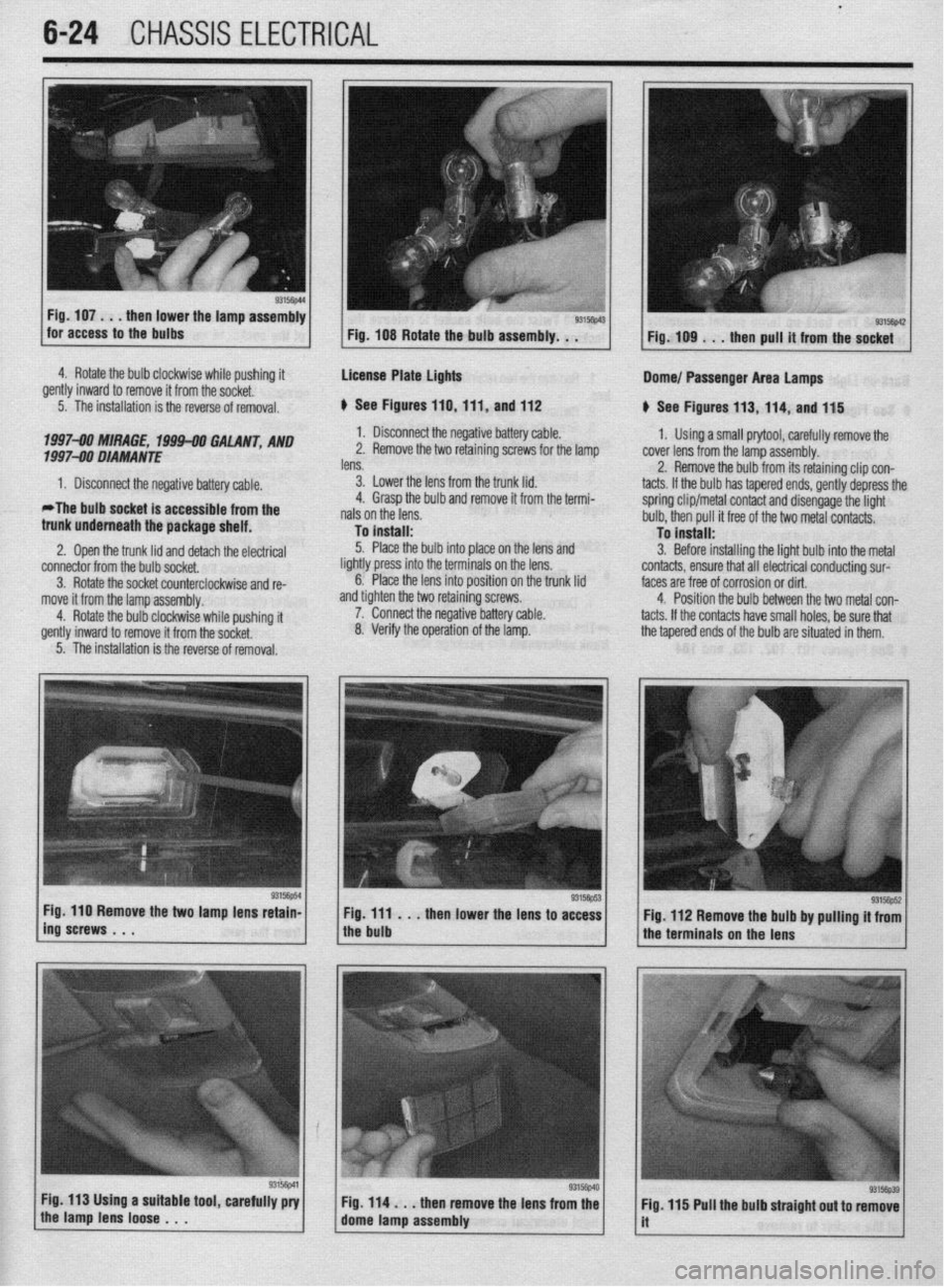
Fig. 107
. . . then lower the lamp assembly
for access to the bulbs
4. Rotate the bulb clockwise while pushing it
.,
gently inward to remove it from the socket.
5. The installation is the reverse of removal.
1997-00 MIRAGE, 1994-00 GALANT, AND
f 997-90 DIAMANTE
1. Disconnect the negative battery cable.
*The bulb socket is accessible from the
trunk underneath the package shelf.
2. Ooen the trunk lid
and detach the elwtrical connector from the bulb socket,
3. Rotate the socket counterclockwise and re-
move it from the lamp assembly.
4. Rotate the bulb clockwise while pushing
it gently inward to remove it from the socket. Fig. 108 Rotate the bulb assembly. . .
License Plate lights
p See Figures 110,111, and 112
1. Disconnect the negative battery cable.
2. Remove the two retaining screws for the lamp
lens.
3. Lower the lens from the trunk lid.
4. Grasp the bulb and remove it from the termi-
nals on the lens.
To install:
5. Place the bulb into place on the lens and
lightly press into the terminals on the lens.
6. Place the lens into position on the trunk lid
and tighten the two retaining screws.
7. Connect the negative battery cable.
8. Verify the operation of the lamp. Dome/ Passenger Area lamps
p See Figures 113, 114, and 115
1, Using a small prytool, carefully remove the
cover lens from the lamp assembly.
2. Remove the bulb from its retaining clip con-
tacts. If the bulb has tapered ends, gently depress the
spring clip/metal contact and disengage the light
bulb, then pull it free of the two metal contacts.
To install:
3. Before installing the light bulb into the metal
contacts, ensure that all electrical conducting sur-
faces are free of corrosion or dirt.
4. Position the bulb between the two metal con-
tacts. If the contacts have small holes, be sure that
the tapered ends of the bulb are situated in them.
5. The installation is the reverse of removal.
Fig. 110 Remove the two lamp lens retain-
ing screws . . . Fig. ill . . .
then lower the lens to access
the bulb Fig. 112 Remove the bulb by pulling it from
the terminals on the lens
Page 229 of 408
6-26 CHASSIS ELECTRICAL
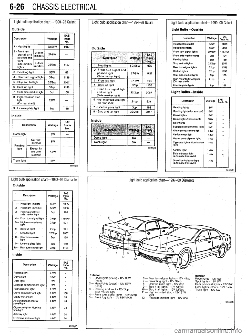
Light bulb application chart-199&93 Galant
Light bulb application chart-1994-98 Galant
Description
1 Wattage 1
rrunk lrght Overdrwe rndvzator light
lautomatlc transaxle)
Light bulb application chart-1992-96 Diamante
Light bulb application chart-1997-00 Diamante
Outside
Description
wattage SAE
trade
NO
1 - Headlrght Irnslde)
65W
9005
l----if
2 - HeadlIght loutsldel
55w 9006
3 - Parktng and front
3cP 168
s!de markrr l,ght
4 - Front turn-srgnal light
24cp 1156NA
5 - Hugh-mounted stop
lbght 21cp
921
1 6- Eackuplrght
I 1921 21cp
7 - Stop/tall light
8 - Rear side marker
lkght
9 - License plate light
3cP 168
IO - Rear turn-slgnal lkght
32cp
1156
Description
Wattage
Dome light
Door light
Luggage compartment lrght
Rear personal lrght
Glove compartment lbght
Vanity mrrror lkght
Arr condltfoner control
panel lkght
Cigarette lighter rllumrna-
llcm l1gbt
Outside
7 t License plate Ilght / 3cp
168
6 Stop and tall Irghl 1 32/2cp 1 2057 I
Inside
Light bulb application chart-1999-00 Galant
Light Bulbs -Outside
Descrrptron Wattage
HeadlIght loutsldel 55W
Headlight (Inside1 65W
Front turn-srgnal lkghts 271B\1\1
Fronr srde-marker lrghts
ZCP
Parkrng hghts
3CP
Stop and tarllrghts 3212~~
Rear turn-srgnal lrghts
32cp
Backup lkghts
32~x1
Rear srde-marker lkghts
3CP SAE
Trade No
---
90a
9005
1157NA
199
168
2057
1156
1156
168
LI- 168
Descrrptron Wattage
- . ..-- -- --_ .---
8W
8W
8W
low
5W
5W
14w
14W
t4w
t4w
Ashtray light
Shtft tndrcaror Ilght
fautomatlc Iransaxlel
Exterior
interior
1 - He;;;fghts (inner) - 12V 65W
2- keadlights (outer) 12V 55W
fHB41 6 - Rear tdm-stgnal lights 12V 45cp
7 - Reversrng light - 12V 32cp
6 - Lrcense plate light 12V 3cp
9 - Stop I tall lights 12V 43/3cp
lo- Stop I tall Ibghts 12V 3212~~
11- Hugh mounted stop - 12V 21W
light RoomlIghts 12V 6W
Spot lights 12V RW
Rear personal lrglils - 1% 8W
Door IIghts (clear) 12V 3 4W
Trunk hght - 12V 5W 3 - Parking and front - 12V 3cp
side marker lrght
4 - Fronl turn-slgnal lights 12V 32cp
5 - Front fog llghl 12V 55W (H3)
12- RearsIde-marker light - 12V 3cp