1900 MITSUBISHI DIAMANTE trunk
[x] Cancel search: trunkPage 316 of 408
.
SUSPENSION AND STEERING 8-21
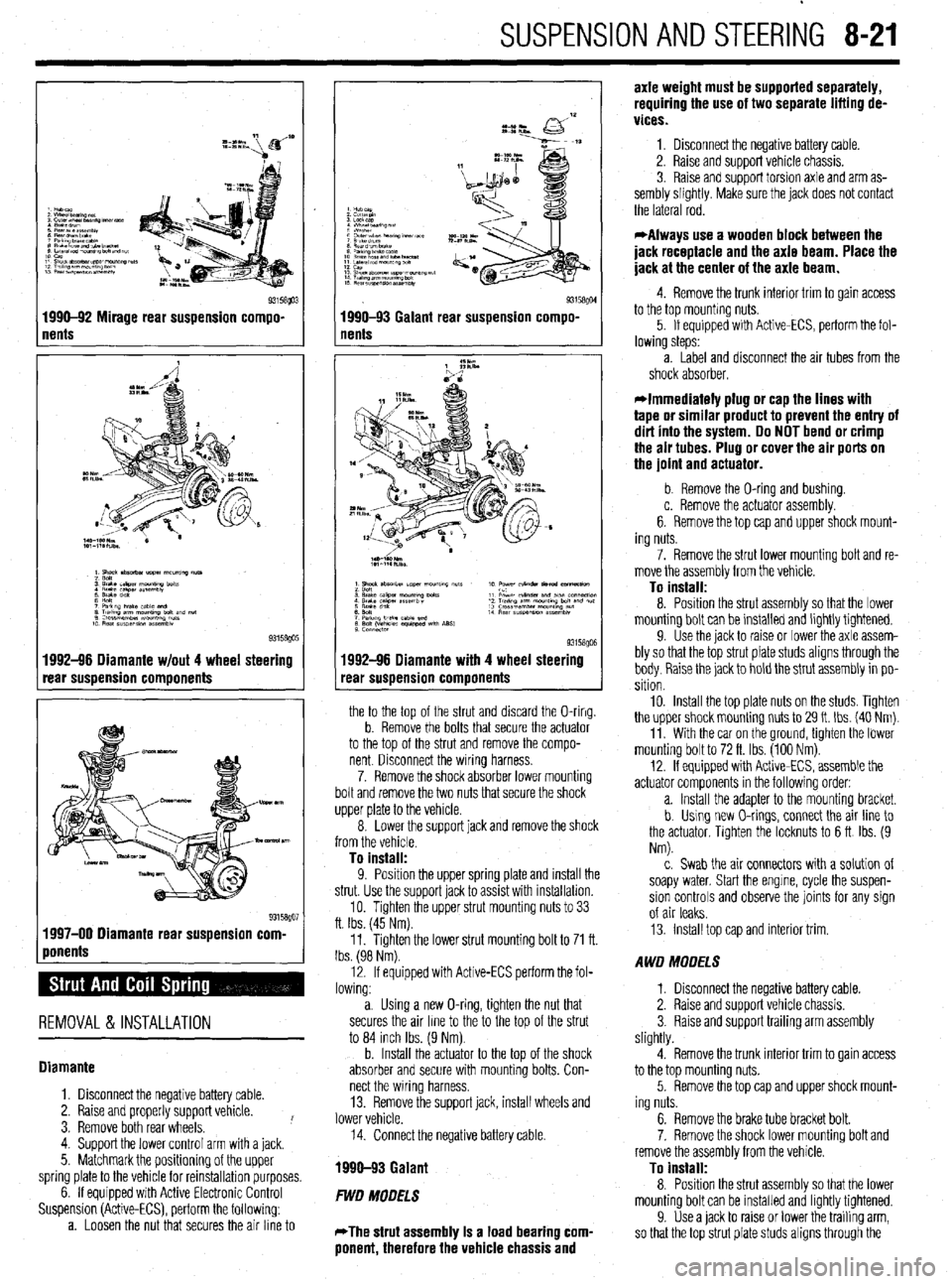
1 nents Q3158!@3 1990-92 Mirage rear suspension compo-
1992-96 Diamante w/out 4 wheel steering
rear suspension components
1 ponents %” 1997-00 Diamante rear suspension corn
REMOVAL & INSTALLATION
Diamante
1. Disconnect the negative battery cable.
2. Raise and properly support vehicle.
3. Remove both rear wheels. !
4. Support the lower control arm with a jack.
5. Matchmark the positioning of the upper
spring plate to the vehicle for reinstallation purposes.
6. If equipped with Active Electronic Control
Suspension (Active-ECS), perform the following:
a. Loosen the nut that secures the air line to
I
93158QM 1990-93 Galant rear suspension compo-
nents
1992-96 Diamante with 4 wheel steering
rear suspension components
the to the top of the strut and discard the O-ring.
b. Remove the bolts that secure the actuator
to the top of the strut and remove the compo-
nent Disconnect the wiring harness.
7. Remove the shock absorber lower mounting
bolt and remove the two nuts that secure the shock
upper plate to the vehicle.
8. Lower the support jack and remove the shock
from the vehicle.
To install:
9. Position the uooer sprina elate and install the
strut. Use the support’jack to as% with installation.
10. Tighten the upper strut mounting nuts to 33
ft. Ibs. (45 Nm).
11. Tighten the lower strut mounting bolt to 71 ft.
Ibs. (98 Nm).
12. If equipped with Active-ECS perform the fol-
lowing:
a. Using a new O-ring, tighten the nut that
secures the air line to the to the top of the strut
to 84 inch Ibs. (9 Nm).
b. Install the actuator to the top of the shock
absorber and secure with mounting bolts. Con-
nect the wiring harness.
13. Remove the support jack, install wheels and
lower vehicle.
14. Connect the negative battery cable.
1990-93 Galant
FWD MODELS
*The strut assembly Is a load bearing com-
ponent, therefore the vehicle chassis and axle weight must be supported separately,
requiring the use of two separate lifting de-
vices.
1. Disconnect the negative battery cable.
2. Raise and support vehicle chassis.
3. Raise and support torsion axle and arm as-
sembly slightly. Make sure the jack does not contact
the lateral rod.
*Always use a wooden block between the
jack receptacle and the axle beam. Place the
jack at the center of the axle beam.
4. Remove the trunk interior trim to gain access
to the top mounting nuts.
5. If equipped with Active-ECS, perform the fol-
lowing steps:
a. Label and disconnect the air tubes from the
shock absorber.
*Immediately plug or cap the lines with
tape or similar product to prevent the entry of
dirt into the system. Do NOT bend or crimp
the air tubes. Plug or cover the air ports on
the joint and actuator.
b. Remove the O-ring and bushing.
c. Remove the actuator assembly.
6. Remove the top cap and upper shock mount-
ing nuts.
7. Remove the strut lower mounting bolt and re-
move the assembly from the vehicle.
To install:
8. Position the strut assembly so that the lower
mounting bolt can be installed and lightly tightened.
9. Use the jack to raise or lower the axle assem-
bly so that the top strut plate studs aligns through the
body. Raise the jack to hold the strut assembly in po-
sition
10. Install the top plate nuts on the studs. Tighten
the upper shock mounting nuts to 29 It. Ibs. (40 Nm).
11. With the car on the ground, tighten the lower
mounting bolt to 72 ft. Ibs. (100 Nm).
12. If equipped with Active-ECS, assemble the
actuator components in the following order:
a. Install the adapter to the mounting bracket.
b. Using new O-rings, connect the air line to
the actuator, Tighten the locknuts to 6 ft Ibs. (9
Nm).
c. Swab the air connectors with a solution of
soapy water. Start the engine, cycle the suspen-
sion controls and observe the joints for any sign
of air leaks.
13. Install top cap and interior trim.
AWD MODELS
1. Disconnect the negative battery cable.
2. Raise and support vehicle chassis.
3. Raise and support trailing arm assembly
slightly.
4. Remove the trunk interior trim to gain access
to the top mounting nuts.
5. Remove the top cap and upper shock mount-
ing nuts.
6. Remove the brake tube bracket bolt.
7. Remove the shock lower mounting bolt and
remove the assembly from the vehicle.
To install:
8. Position the strut assembly so that the lower
mounting bolt can be installed and lightly tightened.
9. Use a jack to raise or lower the trailing arm,
so that the top strut plate studs aligns through the
Page 317 of 408
sembly slightly.
3. In order to gain access to the top mounting
nuts, remove the rear seat as follows:
r
I-- a. While pulling the rear seat stopper out- lb
ward, lift the lower cushion upward. Remove the
lower cushion.
b. Remove the seat back mounting bolts.
c. Lift the seat back upward and remove the
seat.
4. Remove the shock upper mounting nuts.
5. Remove the shock lower mounting bolt and
remove the assembly from the vehicle.
To install:
6. Position the shock assembly so that the
lower mounting bolt can be installed and lightly
tightened.
7. Use a jack to raise or lower the lower control
arm, so that the top shock plate studs align through
the body. Raise the jack to hold the shock assembly
in position.
8 “, In&dl the tnn nlato nl Itc: nn thp dl~rk nnri ,,,“Lu,l .,,” .“* r....” ,.“.., “.. . ..” -.I__-..” tighten the mounting nuts to 32 ft. Ibs. (44 Nm).
9. With the vehicle on the ground, tighten the
lower mounting bolt to 71 ft. Ibs. (98 Nm).
10. Install the rear seat back and cushion.
Miraae
I
1. Remove the trunk interior trim to aain access
to the top mounting nuts.
2. Remove the top cap and upper shock mount-
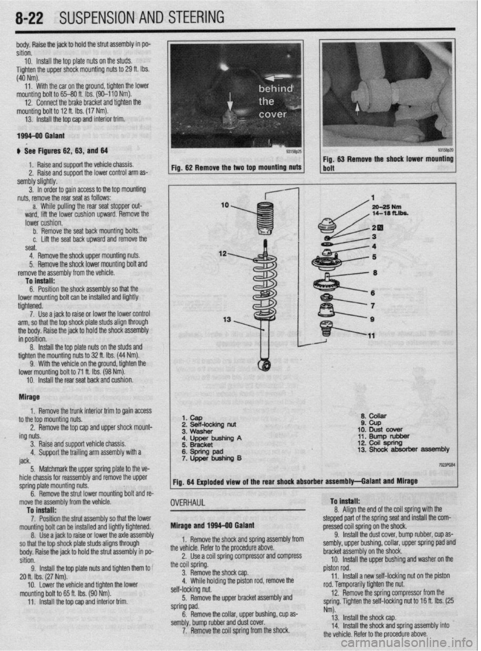
I 1. cap
2 Beif-locking nut
Q* ,A,ll)rrr ii ZPb
10: Dust cbver
11. Bump rubber 12. Coil spring
8-22 SUSPENSION AND STEERING
,
I
ing nuts.
3. Raise andsupport vehicle chassis.
4. Support the trailing arm assembly with a
iack a. ““QJ1vw
;. ~~;~~inp A
6: Spring pad 7. Upper bushing B 13. Shock absorber assembly
I----. 5 Matchmark thF! unner snrino elate to the ve-
I TmFliBl
_. .._._....._... . .._ -TT- _r
u r _.- .-
hicle chassis for reassembly and remove the upper
spring plate mounting nuts.
^ ^
. . .a .I II. I Fig. 64 Exploded view of the rear shock absorber assembly-Galant and Mirage
I
-t
Inrmg DOII ana re-
9.
OVERHAUL To Install:
o A*. .* I b. nemove tne strut lower mol
move the assembly from the vehicle
To install:
7. Position the strut assembly so that the lower
mountino bolt can be installed and liahtlv tiahtened.
8. t&e a jack to raise or lower thk &le&sembly
so that the top shock plate studs aligns through
body. Raise the jack to hold the strut assembly in po-
sition.
9. Install the top plate nuts and tighten them to
20 ft. Ibs. (27 Nm).
mounting bolt to 65 ft. Ibs. (90 Nm).
11. Install the top cap and interior trim. Mirage and 1996-00 Galant 0. ,,ngn me ena of the coil spring with the
stepped part of the spring seat and install the com-
pressed cnil snrinn nn the shock
1. Remove the shock and spring assembly from
the vehicle. Refer to the procedure above.
2. Use a coil spring compressor and compress
the coil spring.
3. Remove the shock cap.
” \w.;,n hrrh~inn +I-.- n;r+nn rnr( rnmn,rc, thn ,. .,,,,,- ,,-,-,* *J ..l” r .I._. * .-_, .-...-.- . ..-
self-locking nut.
5. Remove the upper bracket assembly and
spring pad.
6. Remove the collar, upper bushing, cup as-
sembly, bump rubber and dust cover.
7. Remove the coil spring from the shock. _.. -r,.. J _ _ _ __
9. Install the dust cover, bump rubber, cup as-
sembly, upper bushing, collar, upper spring pad and
bracket assembly on the shock.
10. Install the upper bushing and washer on the
piston rod.
11. Install a new self-locking nut on the piston
roa. temporarily tighten the nut.
12. Remove the spring compressor from the
spring. Tighten the self-locking nut to 16 ft. Ibs. (25
Nm).
13. Install the shock cap.
14. Install the shock and spring assembly into
the v&i&a Rnfnr tn the nmrd~w~ ahnrm
Page 365 of 408
BRAKES 9-29
8. Reinstall the sensor harness with its clamps
and bolts.
9. Reconnect the speed sensor connector.
IO. Install the fender splash shield.
11. Reinstall the tire and wheel, safely lower the
vehicle, and reconnect the negative battery cable. To install: 7. Install the speed sensor and torque to 9 ft.
Ibs. (12 Nm).
8. Install the clips holding the sensor harness.
9. Connect the speed sensor connector.
IO. Connect the negative battery cable.
REAR REAR
) See Figure 131 and 132
1. Disconnect the negative battery cable. Wait at
least 90 seconds before performing any work.
2. Raise and safely support the vehicle. Remove
the necessary tire and wheel assembly.
3. Detach the ABS speed sensor connector.
4. Remove the sensor harness clamp bolts and
clamps.
I) See Figure 133
1. Disconnect the negative battery cable.
5. Remove the ABS speed sensor mounting bolt
and the sensor.
Work must be started after 90 seconds from
the time the ignition switch is turned to the
LOCK position and the negative battery cable
is disconnected.
To install:
6. Install the ABS speed sensor with its mounting
bolt.
*The clearance between the wheel speed
sensor and the rotor’s toothed surface is not
adjustable, but measure the distance be-
tween the sensor installation surface and the
rotor’s toothed surface. Standard value is:
1.11-l .I2 in. (28.2-28.4mm). If not within
specifications, replace the speed sensor or
the toothed rotor.
2. Raise and safely support the vehicle.
3. Detach the speed sensor connector.
4. Remove the clips holding the sensor harness.
5. On AWD models, remove the cable band.
6. Remove the mounting bolt and the speed
sensor with the O-ring.
To install: 7. Install the speed sensor with the O-ring and
torque to 9 ft. Ibs. (12 Nm).
8. Install the clips holding the sensor harness.
9. Install the cable band.
10. Install the sensor wire harness and connect
the connector.
7. Reinstall the sensor harness with its clamps
and bolts.
8. Reconnect the speed sensor connector.
9. Reinstall the tire and wheel, safely lower the
vehicle, and reconnect the negative battery cable.
Diamante
FRONT
* See Figure 133
1. Disconnect the negative battery cable.
Work must be started after 90 seconds from
the time the ignition switch is turned to the
LOCK position and the negative battery cable
is disconnected.
2. Raise and safely support the vehicle.
3. Remove the splash shield.
4. Detach the speed sensor connector.
5. Remove the clips holding the sensor harness.
6. Remove the speed sensor.
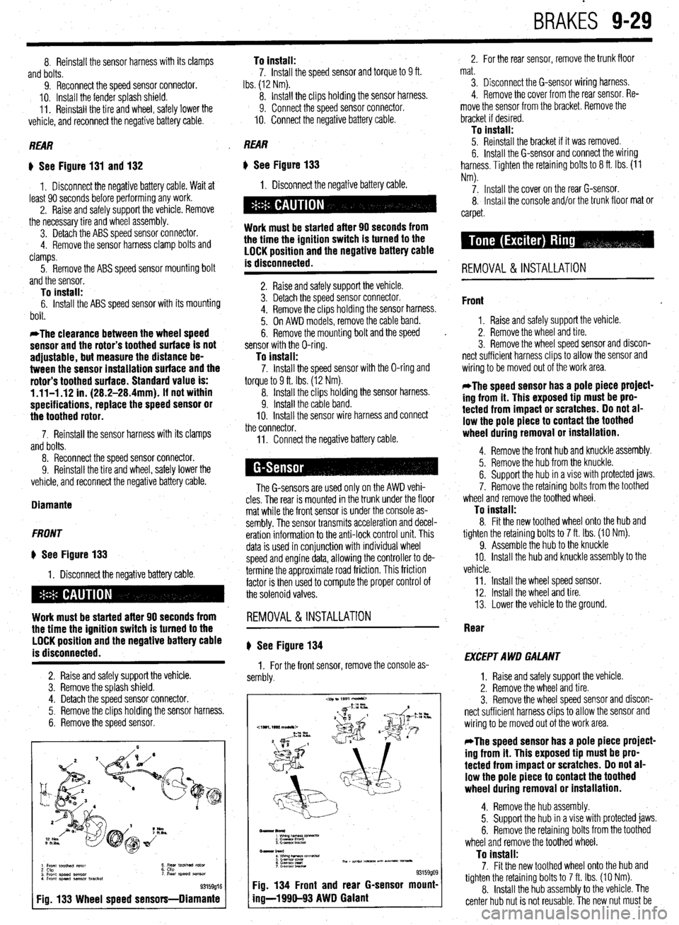
1 Front toothed rotor
2 Ckp
3 Front speed sensor
4 Front speed aenmr bracket t ;5’ toothed rotor ‘I Rear speed SB"SO,
93159016
Fig. 133 Wheel speed sensors-Diamante
11. Connect the negative battery cable.
The G-sensors are used only on the AWD vehi-
cles. The rear is mounted in the trunk under the floor
mat while the front sensor is under the console as-
sembly. The sensor transmits acceleration and decel-
eration information to the anti-lock control unit. This
data is used in conjunction with individual wheel
speed and engine data, allowing the controller to de-
termine the approximate road friction. This friction
factor is then used to compute the proper control of
the solenoid valves.
REMOVAL&INSTALLATION
# See Figure 134
1. For the front sensor, remove the console as-
sembly.
-lkol*)
1 wimp--vx
2 Gasnan I‘m”0
3. Gmwor LmcM
Bmar burl
: wwzh&T&m~mm-
6 G.smsol Ired Th, - ape.24 m-5 un Nt- vmsa*.
7 c-.elwnbRcta
93159909 Fig. 134 Front and rear G-sensor mount-
ing-l 990-93 AWD Galant
2. For the rear sensor, remove the trunk floor
mat.
3. Disconnect the G-sensor wiring harness.
4. Remove the cover from the rear sensor. Re-
move the sensor from the bracket. Remove the
bracket if desired.
To install: 5. Reinstall the bracket if it was removed.
6. Install the G-sensor and connect the wiring
harness. Tighten the retaining bolts to 8 ft. Ibs. (11
Nm).
7. Install the cover on the rear G-sensor.
8, Install the console and/or the trunk floor mat or
carpet.
REMOVAL & INSTALLATION
Front
1. Raise and safely support the vehicle.
2. Remove the wheel and tire.
3. Remove the wheel speed sensor and discon-
nect sufficient harness clips to allow the sensor and
wiring to be moved out of the work area.
*The speed sensor has a pole piece project-
ing from it. This exposed tip must be pro-
tected from impact or scratches. Do not al-
low the pole piece to contact the toothed
wheel during removal or installation.
4. Remove the front hub and knuckle assembly.
5. Remove the hub from the knuckle.
6. Support the hub in a vise with protected jaws.
7. Remove the retaining bolts from the toothed
wheel and remove the toothed wheel.
To install: 8. Fit the new toothed wheel onto the hub and
tighten the retaining bolts to 7 ft. Ibs. (10 Nm).
9. Assemble the hub to the knuckle
IO. Install the hub and knuckle assembly to the
vehicle.
11. Install the wheel speed sensor.
12. Install the wheel and tire.
13. Lower the vehicle to the ground.
Rear
EXCEPT AWD GALANT
1. Raise and safely support the vehicle.
2. Remove the wheel and tire.
3. Remove the wheel speed sensor and discon-
nect sufficient harness clips to allow the sensor and
wiring to be moved out of the work area.
*The speed sensor has a pole piece project-
ing from it. This exposed tip must be pro-
tected from impact or scratches. Do not al-
low the pole piece to contact the toothed
wheel during removal or installation.
4. Remove the hub assembly.
5. Support the hub in a vise with protected jaws.
6. Remove the retaining bolts from the toothed
wheel and remove the toothed wheel.
To install: 7. Fit the new toothed wheel onto the hub and
tighten the retaining bolts to 7 ft. Ibs. (10 Nm).
8. Install the hub assembly to the vehicle. The
center hub nut is not reusable. The new nut must be
Page 369 of 408

EXTERIOR IO-2
DOORS IO-2
REMOVAL&INSTALLATION IO-2
HOOD IO-2
REMOVAL&INSTALLATION IO-2
ALIGNMENT IO-3
HATCH IO-3
REMOVAL & INSTALLATION IO-3
ALIGNMENT IO-3
TAILGATE IO-3
REMOVAL & INSTALLATION IO-3
ALIGNMENT IO-3
TRUNK LID IO-3
REMOVAL &INSTALLATION IO-3
ALIGNMENT IO-3
OUTSIDE MIRRORS IO-3
REMOVAL &INSTALLATION IO-3
ANTENNA IO-4
REPLACEMENT IO-4
FENDERS IO-4
REMOVAL & INSTALLATION IO-4
INTERIOR 1
O-6 INSTRUMENTPANEL IO-6
REMOVAL & INSTALLATION IO-6
FLOOR CONSOLE IO-6
REMOVAL & INSTALLATION IO-6
DOOR PANELS IO-7
REMOVAL & INSTALLATION IO-7
DOORHANDLE/LATCHASSEMBLY IO-IO
REMOVAL &INSTALLATION IO-IO
DOOR LOCKCYLINDER IO-IO
REMOVAL &INSTALLATION IO-IO
HATCH/TAILGATE/TRUNKLID LOCK
CYLINDER IO-IO
REMOVAL &INSTALLATION IO-IO
TAILGATE/HATCH HANDLE IO-IO
REMOVAL &INSTALLATION IO-IO
DOORGLASSANDREGULATOR IO-IO
REMOVAL&INSTALLATION IO-IO
ELECTRIC WINDOW MOTOR IO-IO
REMOVAL &INSTALLATION IO-IO
INSIDE REAR VIEW MIRROR IO-IO
REPLACEMENT IO-IO
SEATS IO-IO
REMOVAL & INSTALLATION IO-IO
POWERSEATMOTOR IO-11
REMOVAL &INSTALLATION IO-11
SPECIFICATIONS CHART
TORQUE SPECIFICATIONS IO-14
4
Page 372 of 408
10-4 BODYANDTRIM
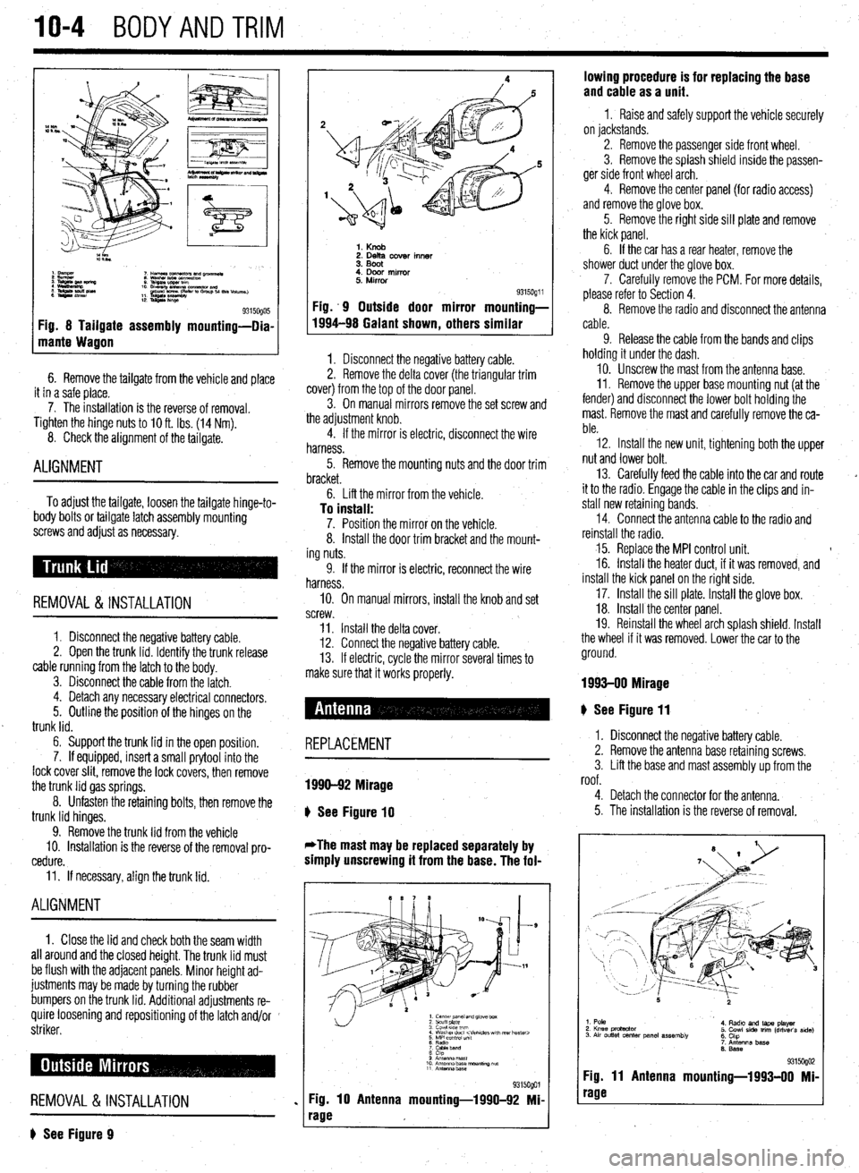
Fig. 8 Tailgate assembly mounting-Dia-
mante Wagon
6. Remove the tailgate from the vehicle and place
it in a safe place.
7. The installation is the reverse of removal.
Tighten the hinge
nuts to IO ft. Ibs. (14 Nm).
8. Check the alignment of the tailgate.
ALIGNMENT
To adjust the tailgate, loosen the tailgate hinge-to-
body bolts or tailgate latch assembly mounting
screws and adjust as necessary.
REMOVAL &INSTALLATION
1. Disconnect the negative battery cable.
2. Open the trunk lid. Identify the trunk release
cable running from the latch to the body.
3. Disconnect the cable from the latch.
4. Detach any necessary electrical connectors.
5. Outline the position of the hinges on the
trunk lid.
6. Support the trunk lid in the open position.
7. If equipped, insert a small prytool into the
lock cover slit, remove the lock covers, then remove
the trunk lid gas springs.
8. Unfasten the retaining bolts, then remove the
trunk lid hinges.
9. Remove the trunk lid from the vehicle
10. Installation is the reverse of the removal pro-
cedure.
11. If necessary, align the trunk lid.
ALIGNMENT
1. Close the lid and check both the seam width
all around and the closed height. The trunk lid must
be flush with the adjacent panels. Minor height ad-
justments may be made by turning the rubber
bumpers on the trunk lid. Additional adjustments re-
quire loosening and repositioning of the latch and/or
striker.
REMOVAL &INSTALLATION
? See Figure 9
1. Knob 2. Delta cover inner
3. Boot
4. Door mirror
5. Mirror
Fig. .9 Outside door mirror
1994-98 Galant shown
, others 9315oQ1 i mounting-
similar
1. Disconnect the negative battery cable.
2. Remove the delta cover (the triangular trim
cover) from the top of the door panel.
3. On manual mirrors remove the set screw and
the adjustment knob.
4. If the mirror is electric, disconnect the wire
harness.
5. Remove the mounting nuts and the door trim
bracket.
6. Lift the mirror from the vehicle.
To install: 7. Position the mirror on the vehicle.
8. Install the door trim bracket and the mount-
ing nuts.
9. If the mirror is electric, reconnect the wire
harness.
IO. On manual mirrors, install the knob and set
screw.
11. Install the delta cover.
12. Connect the negative battery cable.
13. If electric, cycle the mirror several times to
make sure that it works properly.
# See Figure 11
REPLACEMENT
1990-92 Mirage
b
See Figure 10
*The mast may be replaced separately by
simply unscrewing it from the base. The fol-
1. center panel and glove box
2 scuff plate
3 cowl 51ae wm
4 Washer duct
7 CaMeband
8 cap
9 Anrsnna mast
10 Antenna base “ourmng ““f
11 Antennz.base
%i%Qol
Fig. 10 Antenna mounting-1990-92 Mi-
rage lowing procedure is for replacing the base
and cable as a unit.
1 I Raise and safely support the vehicle securely
on jackstands.
2. Remove the passenger side front wheel.
3. Remove the splash shield inside the passen-
ger side front wheel arch.
4. Remove the center panel {for radio access)
and remove the glove box.
5. Remove the right side sill plate and remove
the kick panel.
6. If the car has a rear heater, remove the
shower duct under the glove box.
7. Carefully remove the PCM. For more details,
please refer to Section 4.
8. Remove the radio and disconnect the antenna
cable.
9. Release the cable from the bands and clips
holding it under the dash.
10. Unscrew the mast from the antenna base.
II. Remove the upper base mounting nut (at the
fender) and disconnect the lower bolt holding the
mast. Remove the mast and carefully remove the ca-
ble.
12. Install the new unit, tightening both the upper
nut and lower bolt.
13. Carefully feed the cable into the car and route
it to the radio. Engage the cable in the clips and in-
stall new retaining bands.
14. Connect the antenna cable to the radio and
reinstall the radio.
15. Replace the MPI control unit. t
16. Install the heater duct, if it was removed, and
install the kick panel on the right side.
17. Install the sill plate. Install the glove box.
18. Install the center panel.
19. Reinstall the wheel arch splash shield. Install
the wheel if it was removed. Lower the car to the
ground.
1993-00 Mirage
I. Disconnect the negative battery cable.
2. Remove the antenna base retaining screws.
3. Lift the base and mast assembly up from the
roof.
4. Detach the connector for the antenna.
5. The installation is the reverse of removal.
1. Pole
2. Knee protactor
3. Air outlet center panel assembly 4. Radto and laps player
5. Cowl side trim (driver’s side)
6. Chp
7. Antenna base
6. Base
931 !iogo2 Fig. 11 Antenna mounting-1993-00 Mi-
rage
Page 373 of 408
BODYANDTRIM IO-5
Pole antenna Motor antenna
Pob Antennr
1 Trunk man side tram
Refer to GHOUP 52-Tnm.1
2 Antenna mast
3 Amg nut
4 Feeder wre connect,~n
5 Antenna base
Motor Antenna 1 Trunk mom side trim
(Refer to GROUP 52-Trim )
2 Ring nut
3 Harness connect,~n
4 Feeder wre connectu~n
5 Motor antenna assembly
Fig. 12 Antenna mounting-Galant 9315ogo3
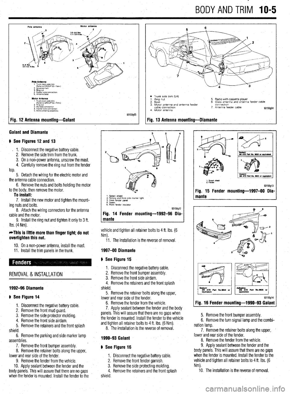
;alant and Diamante
+ See Figures 12 and 13
. 1. Disconnect the negative battery cable.
2. Remove the side trim from thetrunk.
3. On a non-power antenna, unscrew the mast.
4. Carefully remove the ring nut from the fender
top.
5. Detach the wiring for the electric motor and
the antenna cable connection.
6. Remove the nuts and bolts holding the motor
to the body, then remove the motor.
To install: 7. Install the new motor and tighten the mount-
ing nuts and bolts.
8. Attach the wiring connectors for the antenna
cable and the motor.
9. Install the ring nut and tighten it only to 3 ft.
Ibs. (4 Nm).
*This is little more than finger tight; do not
overtighten this nut.
IO. On a non-power antenna, install the mast.
11. Install the trim panels in the trunk.
REMOVAL&INSTALLATION
1992-96 Diamante
+ See Figure 14
1. Disconnect the negative battery cable.
2. Remove the front mud guard.
3. Remove the side protector molding.
4. Remove the front side airdam.
5. Remove the retainers and the front splash
shield.
6. Remove the parking and side marker lamp
assemblies.
7. Remove the front bumper assembly.
8. Remove the retainer bolts along the upper,
lower and rear side of the fender.
9. Remove the fender from the vehicle.
IO. Apply sealant between the fender and the
body panels. This will assure that there are no gaps
when the fender is mounted. Install the fender to the
0 Trunk side tnm (LH)
1 Rmg nut
2. Base
3. Motor antenna and antenna feeder
cable connectlon
4 Motor antenna 5 Radio with cassette player
6 Glass antenna and antenna feeder cable
connectton
7. Antenna feeder cable
9315Ogo4
Fig. 13 Antenna mounting-Diamante
1. Splash shield
2 Parkmg and front side marker light
3 Front fender panel 4. Sealer
5 Front fender insulator 9315OglZ Fig. 14 Fender mounting-1992-96 Dia-
mante
vehicle and tighten all retainer bolts to 4 ft. Ibs. (6
Nm).
11. The installation is the reverse of removal.
1997-00 Diamante
) See Figure 15
1. Disconnect the negative battery cable.
2. Remove the front bumper assembly.
3. Remove the front side airdam.
4. Remove the retainers and the front splash
shield.
5. Remove the retainer bolts along the upper,
lower and rear side of the fender.
6. Remove the fender from the vehicle.
7. Apply sealant between the fender and the body
panels. This will assure that there are no gaps when
the fender is mounted. Install the fender to the vehicle
and tighten all retainer bolts to 4 ft. Ibs. (6 Nm).
8. The installation is the reverse of removal.
1990-93 Galant
b See Figure 16
1. Disconnect the negative battery cable.
2. Remove the front fender garnish.
3. Remove the side protecting molding.
4. Remove the retainers and the front splash
shield.
I
I
1. splash shWd
2. Fender
931sog13 Fig. 15 Fender mounting-1997-00 Dia-
mante
9315og14 Fig. 16 Fender mounting-1990-93 Galant
5. Remove the front bumper assembly.
6. Remove the turn signal lamp and the combi-
nation lamp.
7. Remove the retainer bolts along the upper, ’
lower and rear side of the fender.
8. Remove the fender from the vehicle.
9. Apply sealant between the fender and the
body panels. This will assure that there are no gaps
when the fender is mounted. Install the fender to the
vehicle and tighten all retainer bolts to 4 ft. Ibs. (6
Nm).
10. The installation is the reverse of removal.
Page 379 of 408
BODYANDTRiVl 1041
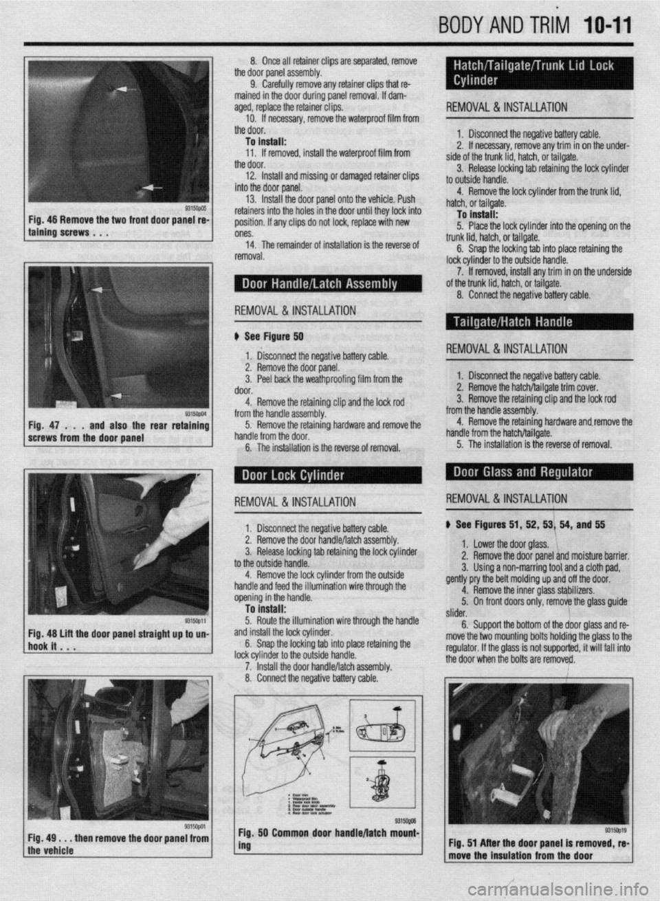
8. llnm all mtainar din!: xc! .wnnratmi rmnnve -.*I-_.. .I._. ..I. -..r-~.--“* -.-.- I( .” .I._._ the dot jr panel assembly.
9. Carefully remove any retainer clips that re-
mained in the door during panel removal. If dam-
aaed. reolace the retainer clios.
- 10. if necessary, remove’the waterproof film from
the door.
To install:
11. If removed, install the waterproof film from
. .
tne aoor.
12. Install and missing or damaged retainer clips
into the door panel.
- .- ” - 13. . - Install the door panel onto the vehicle. Push . - -. ” - ret;liners intn the hnlss in the rlnnr until thev lnck intn . - - - -. -. . . . “, - ” . .- position. If any clips do not lock, replace with new 4. Remove the lock cylinder from the trunk lid,
hatch, or tailgate. T- 1-a-11.
REMOVAL &INSTALLATION
1. Disconnect the r
negative battery cable.
2. If necessary, ren love any trim in on the under-
side of the trunk lid, hz
Itch, or tailgate.
3. Release locking tab retaining the lock cylinder
to outside handle.
9315opo5 1 Fig. 46 Remove the two front door panel re-
taining screws . , . IU Inrlall; 5. Place the lock cylinder into the opening on the
ones.
14. The remainder of installation is the reverse of
removal. trunk lid, hatch, or tailsate. -
6. Snap the locking tab into place retaining the
lock cylinder to the outside handle.
7. If removed, install any trim in on the underside
of the trunk lid, hatch, or tailgate.
8. Connect the negative battery able:
REMOVAL &INSTALLATION
II See Figurd 50
1‘ &connect the negative battery cable. REMOVAL&INSTALLATION
9315ctpm Fig. 47 . . .
and also the rear retaining
screws from the door panel 2. Remove the door panel.
3. Peel back the weathproofing film from the
door.
4. Remove the retaining clip and the lock rod
from the handle assembly.
5. Remove the retaining hardware and remove the
handle from the door.
6. The installation is the reverse of removal. 1. Disconnect the negative battery cable.
2. Remove the hatch/tailgate trim cover.
3. Remove the retaining clip and the lock rod
from the handle assembly.
4. Remove the retaining hardware and.remove the
handle from the hatch/tailgate.
5. The installation is the reverse of removal.
I 1. Disconnect the neaative batterv cable. ) See Figures 51, 52, 53/ 54, and 55 REMOVAL&INSTALLATION REMOVAL&INSTALLATION
2. Remove the door ~andle/latchassembly.
3. Release locking tab retaining the lock cylinder
to the outside handle.
4. Remove the lock cylinder from the outside
handle and feed the illumination wire through the
opening in the handle.
To install:
5. Route the illumination wire through the handle
and install the lock cylinder.
6. Snap the locking tab into place retaining the
lock cvlinder to the outside handle.
7. ‘Install the door handle/latch assembly.
8. Connect the negative battery cable. 1. Lower the door glass. ‘1,
2. Remove the door panel and moisture barrier.
3. Using a non-marring tool and a cloth pad,
gently pry the belt molding up and off the door.
4. Remove the inner glass sthbilizers.
5. On front doors only, remove the glass guide
/
slider.
6. Support the bottom of the door glass and re-
move the two mounting bolts holdirtg the glass to the
regulator. If the glass is not supporfed, it will fail into
+I%? Ann. . ..hmn hr. l..4+s are remove&.
9315opa Fig, 49 . . . then remove the door panel from
the vehicle 50 Common door handle/latch mount-
I
, Flg. 51 After the door panel is removed, re-
move the Insulation from the door
Page 390 of 408
11-8 TROUBLESHOOTING
Ignition systems may be controlled by, or linked to, the engine fuel management sys-
tem. Similar to the fuel injection system, these ignition systems rely on electronic sen-
sors for information to determine the optimum ignition timing for a given engine speed
and load. Some ignition systems no longer allow the ignition timing to be adjusted.
Feedback from low voltage electrical sensors provide information to the control unit to
determine the amount of ignition advance. On these systems, if a failure occurs the failed
component must be replaced. Before replacing suspected failed electrical components,
carefully inspect the wiring and electrical connectors to the related components. Make
sure the electrical connectors are fully connected, clean and not physically damaged. If
necessary, clean the electrical contacts using electrical contact cleaner. The use of clean-
ing agents not specifically designed for electrical contacts should be avoided, as they
could leave a surface film or damage the insulation of the wiring.
1. Engine makes a knocking or pinging noise when accelerating
a. Check the octane rating of the fuel being used. Depending on the type of driving or
driving conditions, it may be necessary to use a higher octane fuel.
b. Verify the ignition system settings and operation. Improperly adjusted ignition timing
or a failed component, such as a knock sensor, may cause the ignition timing to ad-
vance excessively or prematurely. Check the ignition system operation and adjust, or
replace components as needed.
c. Check the spark plug gap, heat range and condition. If the vehicle is operated in se-
vere operating conditions or at continuous high speeds, use a colder heat range spark
plug. Adjust the spark plug gap to the manufacturer’s recommended specification and
replace worn or damaged spark plugs.
2. Sfarter motor grinds when used
a. Examine the starter pinion gear and the engine ring gear for damage, and replace dam-
aged parts.
b. Check the starter mounting bolts and housing. If the housing is cracked or damaged
replace the starter motor and check the mounting bolts for tightness.
3. Engine makes a screeching noise
a. Check the accessory drive belts for looseness and adjust as necessary.
b. Check the accessory drive belt tensioners for seizing or excessive bearing noises and
replace if loose, binding, or excessively noisy.
c. Check for a seizing water pump. The pump may not be leaking; however, the bearing
may be faulty or the impeller loose and jammed. Replace the water pump.
4. Engine makes a growling noise
a. Check for a loose or failing water pump. Replace the pump and engine coolant.
b. Check the accessory drive belt tensioners for excessive bearing noises and replace if
loose or excessively noisy.
5. Engine makes a ticking or tapping noise
a. On vehicles with hydraulic lash adjusters, check for low or dirty engine oil and top off
or replace the engine oil and filter.
b. On vehicles with hydraulic lash adjusters, check for collapsed lifters and replace failed
components.
c. On vehicles with hydraulic lash adjusters, check for low oil pressure caused by a re-
stricted oil filter, worn engine oil pump, or oil pressure relief valve.
d. On vehicles with manually adjusted valves, check for excessive valve clearance or
worn valve train parts. Adjust the valves to specification or replace worn and defective
parts.
e. Check for a loose or improperly tensioned timing belt or timing chain and adjust or re-
place parts as necessary.
f. Check for a bent or sticking exhaust or intake valve. Remove the engine cylinder head
to access and replace.
6. Engine makes a heavy knocking noise
a. Check for a loose crankshaft pulley or flywheel; replace and torque the mounting
bolt(s) to specification.
b. Check for a bent connecting rod caused by a hydro-lock condition. Engine disassem-
bly is necessary to inspect for damaged and needed replacement parts.
c. Check for excessive engine rod bearing wear or damage. This condition is also asso-
ciated with low engine oil pressure and will require engine disassembly to inspect for
damaged and needed replacement parts,
7. Vehicle has a fuel odor when driven ’ a. Check the fuel gauge level. If the fuel gauge registers full, it is possible that the odor is
caused by being filled beyond capacity, or some spillage occurred during refueling.
The odor should clear after driving an hour, or twenty miles, allowing the vapor canis-
ter to purge.
b. Check the fuel filler cap for looseness or seepage. Check the cap tightness and, if
loose, properly secure. If seepage is noted, replace the filler cap.
c. Check for loose hose clamps, cracked or damaged fuel delivery and return lines, or
leaking components or seals, and replace or repair as necessary. d. Check the vehicle’s fuel economy. If fuel consumption has increased due to a failed
component, or if the fuel is not properly ignited due to an ignition related failure, the
catalytic converter may become contaminated. This condition may also trigger the
check engine warning light. Check the spark plugs for a dark, rich condition or verify
the condition by testing the vehicle’s emissions. Replace fuel fouled spark plugs, and
test and replace failed components as necessary.
5. Vehicle has a rotten egg odor when driven
a. Check for a leaking intake gasket or vacuum leak causing a lean running condition. A
lean mixture may result in increased exhaust temperatures, causing the catalytic con-
verter to run hotter than normal. This condition may also trigger the check engine
warning light. Check and repair the vacuum leaks as necessary.
b. Check the vehicle’s alternator and battery condition. If the alternator is overcharging,
the battery electrolyte can be boiled from the battery, and the battery casing may begin
to crack, swell or bulge, damaging or shorting the battery internally. If this has oc-
curred, neutralize the battery mounting area with a suitable baking soda and water
mixture or equivalent, and replace the alternator or voltage regulator. Inspect, service,
and load test the battery, and replace if necessary.
9. Vehicle has a sweet odor when driven
a. Check for an engine coolant leak caused by a seeping radiator cap, loose hose clamp,
weeping cooling system seal, gasket or cooling system hose and replace or repair as
needed.
b. Check for a coolant leak from the radiator, coolant reservoir, heater control valve or
under the dashboard from the heater core, and replace the failed part as necessary.
c. Check the engine’s exhaust for white smoke in addition to a sweet odor. The presence
of white, steamy smoke with a sweet odor indicates coolant leaking into the combus-
tion chamber. Possible causes include a failed head gasket, cracked engine block or
cylinder head. Other symptoms of this condition include a white paste build-up on the
inside of the oil filler cap, and softened, deformed or bulging radiator hoses.
19. Engine vibraies when idling
a. Check for loose, collapsed, or damaged engine or transmission mounts and repair or
replace as necessary.
b. Check for loose or damaged engine covers or shields and secure or replace as neces-
sary.
11. Engine vibrates during acceleration
a. Check for missing, loose or damaged exhaust system hangers and mounts; replace or
repair as necessary.
b. Check the exhaust system routing and fit for adequate clearance or potential rubbing;
repair or adjust as necessary.
7. Battery goes dead while driving
a. Check the battery condition. Replace the battery if the battery will not hold a charge or
fails a battery load test. If the battery loses fluid while driving, check for an overcharg-
ing condition. If the alternator is overcharging, replace the alternator or voltage regula-
tor. (A voltage regulator is typically built into the alternator, necessitating alternator re-
placement or overhaul.)
b. Check the battery cable condition. Clean or replace corroded cables and clean the bat-
tery terminals.
c. Check the alternator and voltage regulator operation. If the charging system is over or
undercharging, replace the alternator or voltage regulator, or both.
d. Inspect the wiring and wire connectors at the alternator for looseness, a missing .
ground or defective terminal, and repair as necessary.
e. Inspect the alternator drive belt tension, tensioners and condition. Properly tension the
drive belt, replace weak or broken tensioners, and replace the drive belt if worn or
cracked.
2. Battery goes dead overnight
a. Check the battery condition. Replace the battery if the battery will not hold a charge or
fails a battery load test.
b. Check for a voltage draw, such as a trunk light, interior light or glove box light staying
on. Check light switch position and operation, and replace if defective.
c. Check the alternator for an internally failed diode, and replace the alternator if defec-
tive.
1. Engine overheats
a. Check the coolant level. Set the heater temperature to full hot and check for internal air
pockets, bleed the cooling system and inspect for leakage. Top off the cooling system
with the correct coolant mixture.
b. Pressure test the cooling system and radiator cap for leaks. Check for seepage caused
by loose hose clamps, failed coolant hoses, and cooling system components such as
the heater control valve, heater core, radiator, radiator cap, and water pump. Replace
defective parts and fill the cooling system with the recommended coolant mixture.