1900 MITSUBISHI DIAMANTE high beam
[x] Cancel search: high beamPage 4 of 408
I-4 GENERALINFORMATIONAND MAINTENANCE
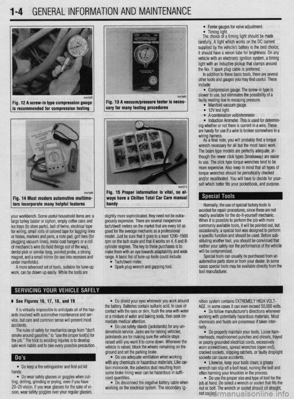
Fig. 12 A screw-in type compression gauge- Fig. 13 A vacuum/pressure tester is neces-
is recommended for compression testing sary for many testing procedures
Fig. 14 Most modern automotive multime-
ters incorporate many helpful features
your workbench. Some useful household items are: a
large turkey baster or siphon, empty coffee cans and
ice trays (to store parts), ball of twine, electrical tape
for wiring, small rolls of colored tape for tagging lines
or hoses, markers and pens, a note pad, golf tees (for
plugging vacuum lines), metal coat hangers or a roll
of mechanic’s wire (to hold things out of the way),
dental pick or similar long, pointed probe, a strong
magnet, and a small mirror (to see into recesses and
under manifolds).
A more advanced set of tools, suitable for tune-up
work, can be drawn up easily. While the tools are
lmvl Fig. 15 Proper information is vital, so at
ways have a Chiiton Total Car Care manua
handy
l Feeler aauoes for valve adiustment
* Timing-light.
The choice of a timing fight should be made
carefully. A light which works on the DC current
supplied by the vehicle’s battery is the best choice;
it should have a xenon tube for brightness. On any
vehicle with an electronic ignition system, a timing
light with an inductive pickup that clamps around
the No. 1 spark plug cable is preferred.
In addition to these basic tools, there are several
other tools and gauges you may find useful. These
include:
l Compression gauge. The screw-in type is
slower to use, but eliminates the possibility of a
fauliy reading due to escaping pressure.
l Manifold vacuum gauge. l 12V test light. l A combination volt/ohmmeter l induction Ammeter. This is used for determin-
ing whether or not there is current in a wire. These
are handy for use if a wire is broken somewhere in a
wiring harness.
As a final note, vou will orobablv find a torque
wrench necessary for all but the most basic work.
The beam type models are perfectly adequate, al-
though the newer click types (breakaway) are easier
to use. The click type torque wrenches tend to be
more expensive. Also keep in mind that all types of
torque wrenches should be periodically checked
and/or recalibrated. You will have to decide for your-
self which better fits your pocketbook, and purpose.
ilightly more sophisticated, they need not be outra-
feously expensive. There are several inexpensive
achldwell meters on the market that are every bit as
Toad for the average mechanic as a professional
nodel. Just be sure that it goes to a least 1200-1500
pm on the tach scale and that it works on 4,6 and 8-
:ylinder engines. The key to these purchases is to
nake them with an eye towards adaptability and wide
ange. A basic list of tune-up tools could include:
l Tach/dwell meter. l Spark plug wrench and gapping tool. Normally, the use of special factory tools is
avoided for repair procedures, since these are not
readily available for the do-it-yourself mechanic.
When it is possible to perform the job with more
commonly available tools, it will be pointed out, but
occasionally, a special tool was designed to perform
a specific function and should be used. Before sub-
stituting another tool, you should be convinced that
neither your safety nor the performance of the vehicle
will be compromised.
Special tools can usually be purchased from an
automotive parts store or from your dealer. In some
cases special tools may be available directly from the
tool manufacturer.
p See Figures 16, 17, 16, and 19
It is virtually impossible to anticipate all of the haz-
ards involved with automotive maintenance and ser-
vice, but care and common sense will prevent most
accidents.
The rules of safety for mechanics range from “don’t
smoke around gasoline,” to “use the proper tool(s) for
the job.” The trick to avoiding injuries is to develop
safe work habits and to take every possible precaution.
Do keep a fire extinguisher and first aid kit
l handy.
Do wear safety glasses or goggles when cut- l ting, drilling, grinding or prying, even if you have
20-20 vision. If you wear glasses for the sake of vi-
sion, wear safety goggles over your regular glasses.
l Do shield your eyes whenever you work around
the battery. Batteries contain sulfuric acid. In case of
contact with the eyes or skin, flush the area with water
or a mixture of water and baking soda, then seek im-
mediate medical attention.
l Do use safety stands (jackstands) for any un-
dervehicle service. Jacks are for raising vehicles;
jackstands are for making sure the vehicle stays
raised until you want it to come down. Whenever the
vehicle is raised, block the wheels remaining on the
ground and set the parking brake.
l Do use adequate ventilation when working
with any chemicals or hazardous materials, Like car-
bon monoxide, the asbestos dust resulting from
some brake lining wear can be hazardous in suffi-
cient quantities.
l Do disconnect the negative battery cable when
working on the electrical system. The secondary ig- nition system contains EXTREMELY HIGH VOLT-
AGE. In some cases it can even exceed 50,000 volts.
l Do follow manufacturer’s directions whenever
working with potentially hazardous materials. Most
chemicals and fluids are poisonous if taken inter-
nally.
l Do properly maintain your tools. Loose ham-
merheads, mushroomed punches and chisels, frayed
or poorly grounded electrical cords, excessively
worn screwdrivers, spread wrenches (open end),
cracked sockets, slipping ratchets, or faulty droplight
sockets can cause accidents.
* Likewise, keep your tools clean; a greasy
wrench can slip off a bolt head, ruining the bolt and
often harming your knuckles in the process.
l Do use the proper size and type of tool for the
job at hand. Do select a wrench or socket that fits the
nut or bolt. The wrench or socket should sit straight,
not cocked.
Page 200 of 408
FUELSYSTiM 5-13
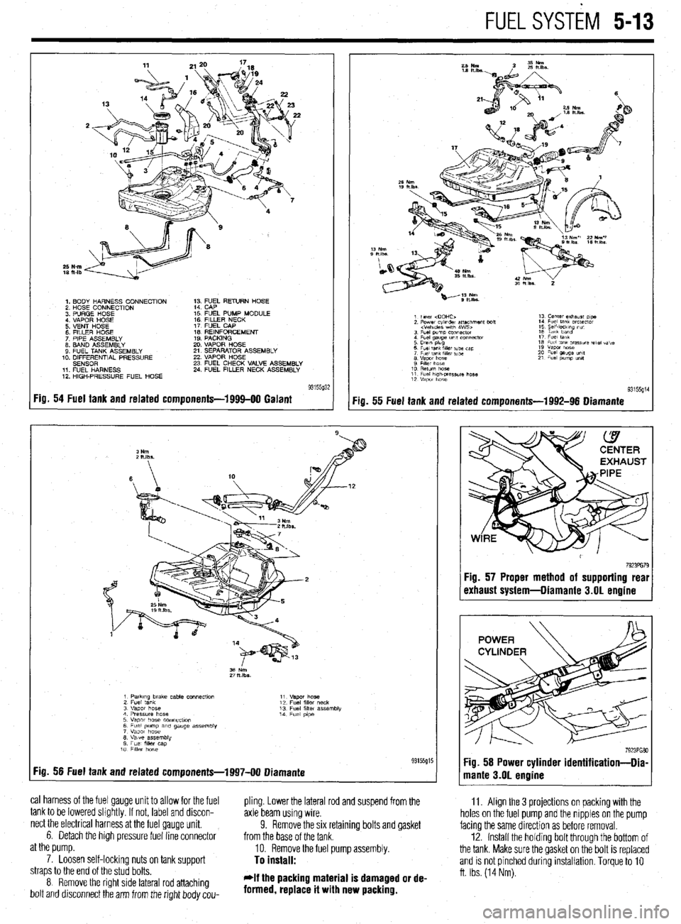
1. BODY HARNESS CONNECTION
2 HOSE CONNECTION
3 PURGE HOSE
4 VAPOR HOSE
5 VENT HOSE
6 FllLER HOSE
7 PIPE ASSEMBLY
8. BAND ASSEMBLY
9 FUEL TANK ASSEMBLY
10. DIFFERENTIAL PRESSURE
SENSOR
11 FUEL HARNESS
12 HIGH-PRESSURE FUEL HOSE 1; ;;JL RETURN HOSE
15 FUEL PUMP MODULE
16 FILLER NECK
17 FUEL CAP
IS REINFORCEMENT
19 PACKING
20 VAPOR HOSE
21 SEPARATOR ASSEMBLY
22 VAPOR HOSE
23 FUEL CHECK VALVE ASSEMBLY
24 FUEL FILLER NECK ASSEMBLY
Fig. 54 Fuel tank and related components-1999-00 Galant
:ia. 55 Fuel tank and related components-1992-96 Diamante
11. Align the 3 projections on packing with the
holes on the fuel pump and the nipples on the pump
facing the same direction as before removal.
12. Install the holdrng bolt through the bottom of
the tank. Make sure the gasket on the bolt is replaced
and is not pinched during installation. Torque to 10
ft. Ibs. (14 Nm).
1 PatkIng brake cable COnneCtlo” 11
2 Fuel tank “.qm hose
12 Fuel fllk, neck
3 “apot hose 13 Fuel filler assembly
4 Pressure hose 14
5 Vapor hose COnneCflOn Fuel p,pe
6 Fuel pump am gauge assembly
7 Vapor hose
8 Valve assembly
9 Fuel mer cap
10 FllkY hose
:ig. 56 Fuel tank and related components-1997-00 Diamante 93155g15
cal harness of the fuel gauge unit to allow for the fuel
pling. Lower the lateral rod and suspend from the
tank to be lowered slightly. If not, label and discon-
axle beam using wire.
nect the electrical harness at the fuel gauge unit.
6. Detach the high pressure fuel line connector 9. Remove the six retaining bolts and gasket
from the base of the tank.
at the pump.
10. Remove the fuel pump assembly.
7. Loosen self-lockinq nuts on tank suooort
To install: straps to the end of the stud bolts.
8 Remove the right side lateral rod attaching
bolt and drsconnect the arm from the right body cou- *If the packing material is damaged or de-
formed, replace it with new packing.
7923PG79 :ig. 57 Proper method of supporting real
rxhaust system-Diamante 3.01 engine
Page 223 of 408
.
6-20 CHASSIS ELECTRICAL
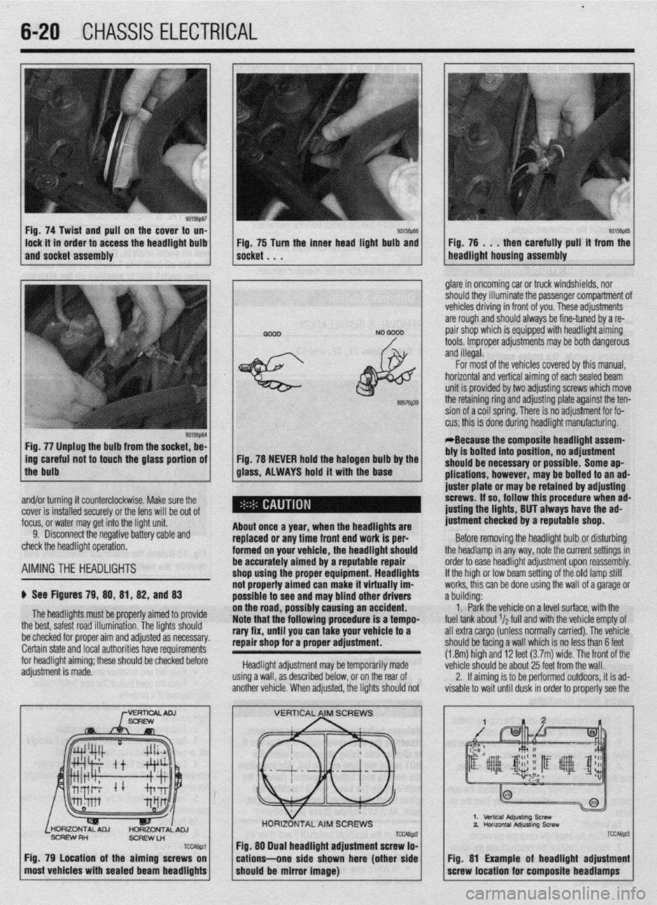
Fig. 74 Twist and pull on the cover to un-
lock it in order to access the headlight bulb
and socket assembly 93Mm Fig, 75 Turn the inner head light bulb and then carefully pull’ it from the
NO 0000 . glare in oncoming car or truck windshields, nor
should they illuminate the passenger compartment of
vehicles driving in front of you. These adjustments
are rough and should always be fine-tuned by a re-
pair shop which is equipped with headlight aiming
tools. Improper adjustments may be both dangerous
and illegal.
Fig. 77 Unplug the bulb from the socket, be-
L
ing careful not to touch the glass portion of
the bulb
I
6957Q39
Fig. 78 NEVER hold the halogen bulb by the
glass, ALWAYS hold it with the base
,
About once a year, when the headllgftts are
replaced or any time front end work is per-
formed on your vehicle, the headlight should
be accurately aimed by a reputable repair
shop uslng the proper equipment. Headlights
not properly aimed can make it virtually im-
possible to see ar Id may blind other drivers
ibly causing an accident.
Note that the’following procedure is a tempo-
rary fix, until you can take your vehicle to a
repair shop for a proper adjustment.
Headlight adjustment may be temporarily made
using a wall, as described below, or on the rear of
another vehicle. When adjusted, the lights should not For most of the vehicles covered by this manual,
horizontal and vertical aiming of eachsealed beam
unit is provided by two adjusting screws which move
the retaining ring and adjusting plate against the ten-
sion of a coil spring. There is no adjustment for fo-
cus; this is done during headlight manufacturing.
*Because the composite headlight assem-
bly is bolted into position, no adjustment
should be necessary or possible. Some ap-
plications, however, may be bolted to an ad-
juster plate or may be retained by adjusting
screws. If so, follow this procedure when ad-
@sting the lights, BUT always have the ad-
justment checked by a reputable shop.
Before removing the headlight bulb or disturbing
the headlamp in any way, note the current settings in
order to ease headlight adjustment upon reassembly.
If the high or low beam setting of the old lamp still
works, this can be done using the wall of a garage or
a building:
1. Park the vehicle on a level surface, with the
fuel tank about r/a full and with the vehicle empty of
all extra cargo (unless normally carried). The vehicle
should be facing a wall which is no less than 6 feet
(1.8m) high and 12 feet (3.7m) wide. The front of the
vehicle should be about 25 feet from the wall.
2. If aiming is to be performed outdoors, it is ad-
visable to wait until dusk in order to properly see the
% and/or turning it counterclockwise. Make sure the
cover is installed securely or the lens will be out of
focus, or water may get into the light unit.
9. Disconnect the negative battery cable and
check the headlight operation.
AIMINGTHE HEADLIGHTS
$ See Figures 79, 88, 81, 82, and 83
The headlights must be proper’ ’ ’ ’
the best, safest road illumination. ’ ’
ly armea IO provrae
The lights should
:.__1__1 __ - -___-_-. on the road, POSSI
be checked for proper aim and adfusreu as IlweSYdly. Certain state and local authorities have requirements
for headlight aiming; these should be checked before
adjustment is made.
SCFEWRH
ScFlEwLn
TCcAssa
Fig. 79 Location of the aiming screws on
most vehicles with sealed beam headlights
TCCAE@ Fig. 88 Dual headlight adjustment screw lo-
cations--one side shown here (other side
should be mirror image)
2.
TCC&z3
Fig. 81 Example of headlight adjustment
screw location for composite headlamps
Page 224 of 408
CHASSIS ELECTRICAL 6-21
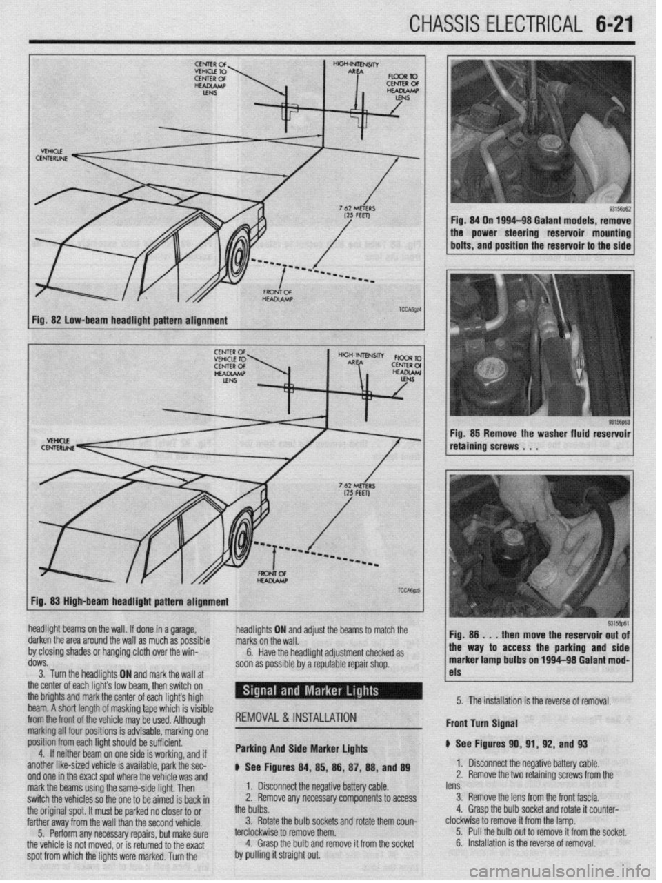
Fig. 82 low-beam headlight pattern alignment
93156pE.3 Fig. 85 Remove the washer fluid reservoir
retaining screws . . .
Fig. 83 High-beam headlight pattern alignment
headlight beams on the wall. If done in a garage,
darken the area around the wall as much as possible
by closing shades or hanging cloth over the win-
dows.
3. Turn the headlights ON and markthe wall at
the center of each light’s low br ram, then switch on
the brights and mark the center of each lights high
beam. A short length of maskin g tape which is visible
from the front of the
whir+ ma . ._..._._ . .._ y be used. Although
marking all four po:
sitions is advisable, marking one
position from each
light should be sufficient.
4. If neithar he; ~. __
Irn on one side is working, and if
another like-sized vehicle is available, park the sec-
nnri nm in the wart cnnt whrw the whirlo um md
headli! jhts ON and adjust the beams to marcn me
I. Disconnect the negative battery cable. marks on the wall.
2. Remove any necessary components to access 6.
the bulbs. Have the headlight adjustment checked as
soon as possible by a reputable repair shop.
3. Rotate the bulb sockets and rotate them coun-
terclockwise to remove them.
4. Grasp the bulb and remove it from the socket REMOVAL&INSTALLATION
Parking And Side Marker Lights
p See Figures 84, 85, 88, 87, 88, and 89 !ss the parking and side
1~ nn loo4-98 Galant mod-
I
1 I-
5315@61
lens. 1 Fio. 8
then move the reservoir out of
3. Remove the lens from the front fascia.
4. Grasp the bulb socket and rotate it counter- marker lamp bult, _.. ._“~-
clockwise to remove it from the lamp.
5. Pull the bulb out to remove it from the socket. 5. The installation is the reverse of removal.
6. Installation is the reverse of removal. Front turn Signal
p See Figures 91
1. Disconnect tl
2. Remove the t 0, 91, 92, and 93
I(? n,-.nn+:.m b.Hnn, nnL.L
z Ill7yau”e “allcly ul”IC. 10 retainino screws from the
spot from which the lights were marked. Turn the . ..I_ WIIY I.8 %,I” V”UVL”fdYI T.II”IU Lll” “VlllUlY ,.UU U,,” mark the beams using the same-side light. Then
switch the vehicles so the one to be aimed is back in
the original spot. It must be parked no closer to or
farther away from the wall than the second vehicle.
5. Perform any necessary repairs, but make sure
the vehicle is not moved, or is returned to the exact
by pulling it straight out.
Page 232 of 408
CHASSIS ELECTRlCiL 6-29
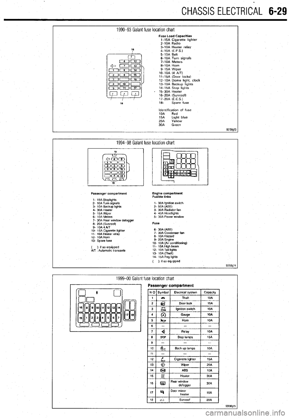
1990-93 Galant fuse location chart Fuse Load Capacities
l-15A Cigarette hghter
Z-10A Radm
3-10A Heater relay
4-10A (E P S.)
5-10A Belt
6-10A Turn signals
7-10A Meters
6-10A Horn
9-15A Wiper
lo-10A (4 A/T)
ll-15A (Door locks)
12-10A Dome hght, clock
13-10A Backup hghts
14-15A Stop hghts
15-30A Heater
16m20A (Sunroof)
17-20A (ECS)
1% spare fuse
ldentlfxation of fuse
10A Red
15A Light blue
20A Yellow
30A Green
93156g13
1994-98 Galant fuse location chart
Passenger compartment
1. 15A StoplIghts
2- 10A Turn signals
3- 1 OA Backup Itghts
4. 30A Heater
5. i5A Wiper
6- IOA Meters
7. 30A Rear wndow defogger
;: fo& fl$oof)
IO- 15A Cagaretle lighler
11. 10A Heater relay
12. IOA Horn
13. Spare fuse
( ): II so equipped
A!T Automallc transaxle Engine compartment
Fusible links
I- 30A Ignition swlch
2. 50A (ABS)
3. 30A Radiator fan
4. 40A Headkghts
5. 30A Power wndow
Fuse
6- 30A (ABS)
7. 30A Condenser fan
6. 10A Hazard
9. 20A Engine
10. 10A (Au conditioning)
11. 10AHigh beam
12. 10ATall lkghts
13. 10A (Theft)
14. i5A Fog lkghls
( ): If so equipped
93156g14
1999-00 Galant fuse location chart
Page 386 of 408
11-4 TROUBLESHOOTING
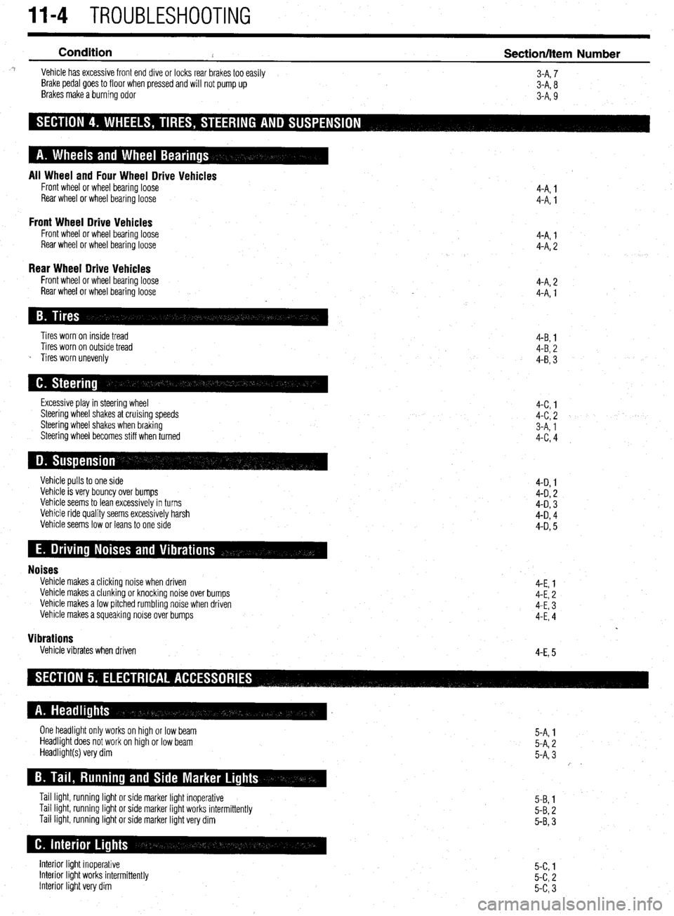
Condition
2 Section/Item Number ^i Vehicle has excessive front end dive or locks rear brakes too easily
3-A, 7
Brake pedal goes to floor when pressed and will not pump up
3-A, 8
Brakes make a burning odor
3-A, 9
All Wheel and Four Wheel Drive Vehicles Front wheel or wheel bearing loose
Rear wheel or wheel bearingloose
Front Wheel Drive Vehicles Front wheel or wheel bearing loose
Rear wheel or wheel bearing loose 4-A. 1
4-A: 1
4-A, 1
4-A, 2
Rear Wheel Drive Vehicles Front wheel or wheel bearing loose
Rear wheel or wheel bearing loose 4-A, 2
4-A, 1
Tires worn on inside tread
Tires worn on outside tread
s Tires worn unevenly 4-B, 1
4-B, 2
4-B, 3
Excessive play in steering wheel
Steering wheel shakes at cruising speeds
Steering wheel shakes when braking
Steering wheel becomes stiff when turned 4-c, 1
4-c, 2
3-A, 1
4-c, 4
Vehicle pulls to one side
Vehicle is very bouncy over bumps
Vehicle seems to lean excessively in turns
Vehicle ride quality seems excessively harsh
Vehicle seems low or leans to one side 4-D 1
4-D, 2
4-D, 3
4-D, 4
4-D, 5
Noises Vehicle makes a clicking noise when driven
Vehicle makes a clunking or knocking noise over bumps
Vehicle makes a low pitched rumbling noise when driven
Vehicle makes a squeaking noise over bumps
Vibrations Vehicle vibrates when driven 4-E, 1
4-E, 2
4-E, 3
4-E, 4
4-E, 5
One headlight only works on high or low beam
Headlight does not work on high or low beam
Headlight(s) very dim
Tail light, running light or side marker light inoperative
Tail light, running light or side marker light works intermittently
Tail light, running light or side marker light very dim 5-A, 1
5-A, 2
5-A, 3
/ .
5-B, 1
5-B, 2
5-B, 3
Interior light inoperative
Interior light works intermittently
Interior light very dim 5-c, 1
5-c, 2
5-c, 3
Page 395 of 408
TROUBLESHOOTING 11-13
NOTE: When one shock fails, ft is recommended to replace front or rear
units as pairs.
3. Vehicle leans excessively in turns
a. Check for worn or leaking shock absorbers or strut assemblies and replace as neces-
sary.
b. Check for missing, damaged, or worn stabilizer links or bushings, and replace or in-
stall as necessary.
4. Vehicle ride quality seems excessively ha&h
a. Check for seized shock absorbers or strut assemblies and replace as necessary.
b. Check for excessively high tire pressures and adjust pressures to vehicle recommen-
dations.
5. Vehicle seems low or leans to one side
a. Check for a damaged, broken or weak spring. Replace defective parts and check for a
needed alignment.
b. Check for seized shock absorbers or strut assemblies and replace as necessary.
c. Check for worn or leaking shock absorbers or strut assemblies and replace as neces-
sary.
Noises 1. Vehicle makes a clicking noises when driven
a. Check the noise to see if it varies with road speed. Verify if the noise is present when
coasting or with steering or throttle input. If the clicking noise frequency changes with
road speed and is not affected by steering or throttle input, check the tire treads for a
stone, piece of glass, nail or another hard object imbedded into the tire or tire tread.
Stones rarely cause a tire puncture and are easily removed. Other objects may create
an air leak when removed. Consider having these objects removed immediately at a
facility equipped to repair tire punctures.
b. If the clicking noise varies with throttle input and steering, check for a worn Constant
Velocity (CV-joint) joint, universal (U- joint) or flex joint.
2. Vehicle makes a clunking or knocking noise over bumps
a. A clunking noise over bumps is most often caused by excessive movement or clear-
ance in a suspension component. Check the suspension for soft, cracked, damaged or
worn bushings. Replace the bushings and check the vehicle’s alignment.
b. Check for loose suspension mounting bolts. Check the tightness on subframe bolts,
pivot bolts and suspension mounting bolts, and torque to specification.
c. Check the vehicle for a loose wheel bearing. Some wheel bearings can be adjusted for
looseness, while others must be replaced if loose. Adjust or replace the bearings as
recommended by the manufacturer.
d. Check the door latch adjustment. If the door is slightly loose, or the latch adjustment
is not centered, the door assembly may create noises over bumps and rough surfaces.
Properly adjust the door latches to secure the door. 3. Vehicle makes a low pitched rumbling noise when driven
a. A low pitched rumbling noise is usually caused by a drive train related bearing and is
most often associated with a wheel bearing which has been damaged or worn. The
damage can be caused by excessive brake temperatures or physical contact with a pot
hole or curb. Sometimes the noise will vary when turning. Left hand turns increase the
load on the vehicle’s right side, and right turns load the left side. A failed front wheel
bearing may also cause a slight steering wheel vibration when turning. A bearing
which exhibits noise must be replaced.
b. Check the tire condition and balance. An internally damaged tire may cause failure
symptoms similar to failed suspension parts. For diagnostic purposes, try a known
good set of tires and replace defective tires.
4. Vehicle makes a squeaking noise over bumps
a. Check the vehicle’s ball joints for wear, damaged or leaking boots. Replace a ball joint
if it is loose, the boot is damaged and leaking, or the ball joint is binding. When re-
placing suspension parts, check the vehicle for alignment.
b. Check for seized or deteriorated bushings. Replace bushings that are worn or dam-
aged and check the vehicle for alignment.
c. Check for the presence of sway bar or stabilizer bar bushings which wrap around the
bar. Inspect the condition of the bushings and replace if worn or damaged. Remove
the bushing bracket and apply a thin layer of suspension grease to the area where the
bushings wrap around the bar and reinstall the bushing brackets. ~
5. Vehicle vibrates when driven
a. Check the road surface. Roads which have rough or uneven surfaces may cause un-
usual vi brations.
b. Check the tire condition and balance. An internally damaged tire may cause failure
symptoms similar to failed suspension parts. For diagnostic purposes, try a known
good set of tires and replace defective tires immediately.
c. Check for a worn Constant Velocity (CV-joint) joint, universal (U- joint) or flex joint
and replace if loose, damaged or binding.
d. Check for a loose, bent, or out-of-balance axle or drive shaft. Replace damaged or
failed components.
NOTE: Diagnosing failures related to wheels, tires, steering and the sus-
pension system can often times be accomplished with a careful and thor-
ough test drive. Bearing noises are isolated by noting whether the noises
or symptoms vary when turning left or right, or occur while driving a
straight line. During a teft hand turn, the vehicle’s weight shifts to the
right, placing more force on the right side bearings, such that if a right side
wheel bearing is worn or damaged, the noise or vibration should increase
during light-to-heavy acceleration. Conversely, on right hand turns, the ve-
hicle tends to lean to the left, loading the left side bearings.
Knocking noises in the suspension when the vehicle is driven over rough roads, rail-
road tracks and speed bumps indicate worn suspension components such as bushings,
ball joints or tie rod ends, or a worn steering system.
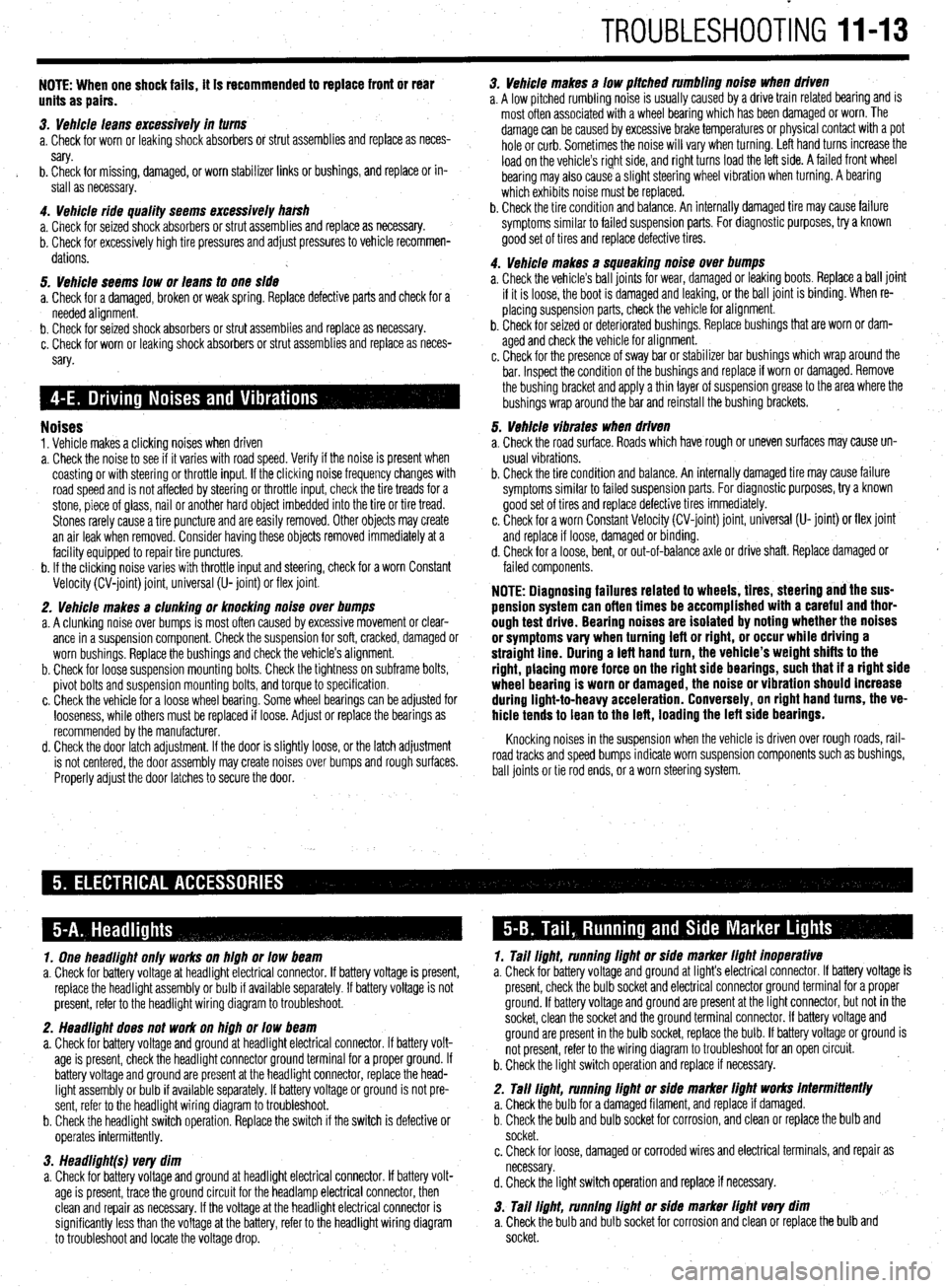
1. One headlight only works on high or low beam
a. Check for battery voltage at headlight electrical connector. If battery voltage is present,
replace the headlight assembly or bulb if available separately. If battery voltage is not
present, refer to the headlight wiring diagram to troubleshoot.
2. Headlight does not work on high or low beam
a. Check for battery voltage and ground at headlight electrical connector. If battery volt-
age is present, check the headlight connector ground terminal for a proper ground. If
battery voltage and ground are present at the headlight connector, replace the head-
light assembly or bulb if available separately. If battery voltage or ground is not pre-
sent, refer to the headlight wiring diagram to troubleshoot.
b. Check the headlight switch operation. Replace the switch if the switch is defective or
ooerates intermittentlv. 1. Tail light, running light or side marker light inoperative
a. Check for battery voltage and ground at light’s electrical connector. If battery voltage is
present, check the bulb socket and electrical connector ground terminal for a proper
ground. If battery voltage and ground are present at the light connector, but not in the
socket, clean the socket and the ground terminal connector. If battery voltage and
ground are present in the bulb socket, replace the bulb. If battery voltage or ground is
not present, refer to the wiring diagram to troubleshoot for an open circuit.
b. Check the light switch operation and replace if necessary.
2. Tall light, running light or side marker light works intermittently
a. Check the bulb for a damaged filament, and replace if damaged.
b. Check the bulb and bulb socket for corrosion, and clean or replace the bulb and
socket.
w 3. Headlight(s) very dim
a. Check for battery voltage and ground at headlight electrical connector. If battery volt-
age is present, trace the ground circuit for the headlamp electrical connector, then
clean and repair as necessary. If the voltage at the headlight electrical connector is
significantly less than the voltage at the battery, refer to the headlight wiring diagram
to troubleshoot and locate the voltage drop. c. Check for loose, damaged or corroded wires and electrical terminals, and repair as
necessary.
d. Check the light switch operation and replace if necessary.
3. Tail light, running light or side marker light very dim
a. Check the bulb and bulb socket for corrosion and clean or replace the bulb and
socket.