1900 MITSUBISHI DIAMANTE clock setting
[x] Cancel search: clock settingPage 86 of 408

ENGINEANDENGINEOVERHAUL 3-25
When removina the cvlinder head. take care
not to bend or iamag;! the plug guide. The
plug guide can not be replaced.
To install:
22. Thoroughly clean the mating surfaces of the
head and block.
23. Place a new head gasket on the cylinder
block with the identification marks facing upward. Do
not use sealer on the gasket.
24. Carefully install the cylinder head on the
block.
25. Measure the cylinder head bolts prior to in-
stallation Replace any that exceed 3.795 in.
(96.4mm)
26. Apply a small amount of engine oil to the
thread section of the bolt and install so the chamfer
of the washer faces upward.
27. Tighten the cylinder head bolts as follows:
a. In the proper tightening sequence, torque
bolts to 54 ft. Ibs. (75 Nm).
b. In the reverse order of the tightening se-
quence, fully loosen all bolts.
c In the proper trghtening sequence, torque
bolts to 14 ft. Ibs. (20 Nm).
d. In the proper tightening sequence, tighten
bolts 1/4 turn (90 degrees).
e. In the proper tightening sequence, tighten
bolts an additional 1/4 turn (90 degrees).
28. Install the camshaft sprocket and tighten the
bolt to 65 ft. Ibs (90 Nm), while holding the sprocket
in place using the appropriate wrench. Confirm
proper timing mark alignment.
29. Install the upper timing belt cover and rocker
cover. Torque the rocker cover bolts to 29 inch Ibs.
(3 Nm).
30. Loosen the water pipe mounting bolt for ease
of thermostat housing installation.
31. Apply a thin bead of sealant MD970389 or
equivalent, to the water tube connection on the ther-
mostat case.
32. Apply a small amount of water to the O-ring
of the water inlet pipe and press the thermostat case
assembly onto the water inlet pipe. Install the ther-
mostat case assembly mounting bolt tightening to 16
ff. Ibs. (22 Nm).
l ECT sensor and gauge sender l IAC motor 33. Tighten the water pipe mounting bolt.
34. Install the thermostat into the housing so the
jiggle valve is located at the top. Tighten the housing
bolts to 10 ft. Ibs (14 Nm).
35. Attach the wiring to the following compo-
nents:
l HO& sensor
l EGR temperature sensor l TP sensor l Knock sensor l Fuel injectors
36. Connect the upper radiator hose to the ther-
mostat housing.
37. Connect the accelerator cable connection to
the throttle body.
38. Connect the oil pressure switch.
39. Install the spark plug wires,
40. Connect the control harness assembly.
41. Replace the O-ring for the high pressure hose
and install a new clamp on the return hose and re-
connect the fuel lines. 42. Install the air intake hose. Connect the
breather hose and air cleaner case cover
43. Reconnect the brake booster and the PCV
vacuum hoses.
44. Fill the system with coolant.
45. Connect the negative battery cable
2.01 SOHC Engine
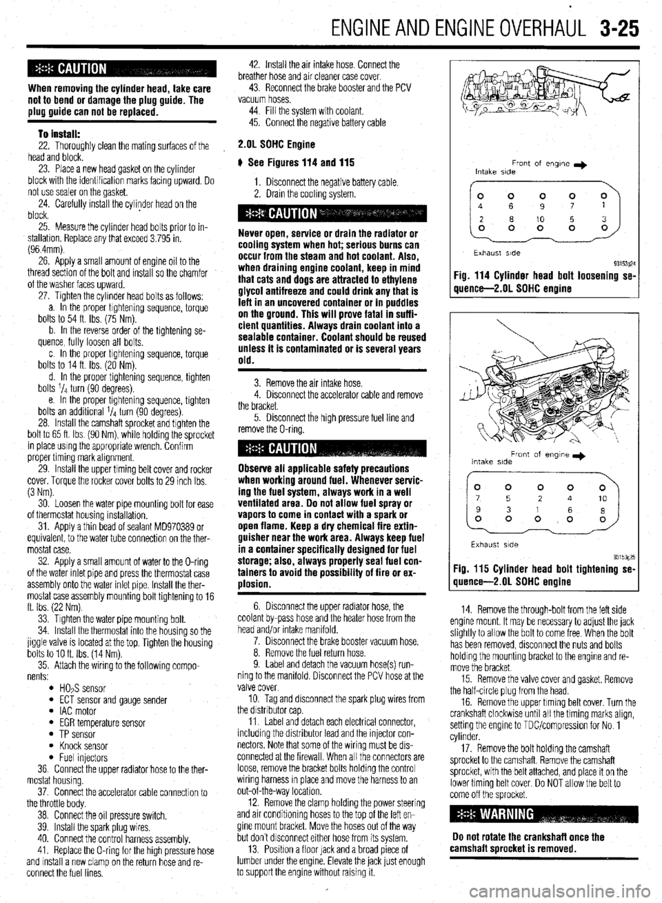
# See Figures 114 and 115
1. Disconnect the negative battery cable.
2. Drain the coolrng system.
Never open, service or drain the radiator or
cooling system when hot; serious burns can
occur from the steam and hot coolant. Also,
when draining engine coolant, keep in mind
that cats and dogs are attracted to ethylene
glycol antifreeze and could drink any that is
left in an uncovered container or in puddles
on the ground. This will prove fatal in suffi-
cient quantities. Always drain coolant into a
sealable container. Coolant should be reused
unless it is contaminated or is several years
old.
3. Remove the air intake hose.
4. Disconnect the accelerator cable and remove
the bracket.
5. Disconnect the high pressure fuel line and
remove the O-ring.
Observe all applicable safety precautions
when working around fuel. Whenever servic-
ing the fuel system, always work in a well
ventilated area. Do not allow fuel spray or
vapors to come in contact with a spark or
open flame. Keep a dry chemical fire extin-
guisher near the work area. Always keep fuel
in a container specifically designed for fuel
storage; also, always properly seal fuel con-
tainers to avoid the possibility of fire or ex-
plosion.
6. Disconnect the upper radiator hose, the
coolant by-pass hose and the heater hose from the
head and/or intake manifold.
7. Disconnect the brake booster vacuum hose.
8. Remove the fuel return hose.
9. Label and detach the vacuum hose(s) run-
ning to the manifold. Disconnect the PCV hose at the
valve cover.
10. Tag and disconnect the spark plug wires from
the drstnbutor cap
11. Label and detach each electrical connector,
including the distributor lead and the injector con-
nectors Note that some of the wiring must be drs-
connected at the firewall. When all the connectors are
loose, remove the bracket bolts holding the control
wiring harness rn place and move the harness to an
out-of-the-way location.
12. Remove the clamp holding the power steering
and air conditioning hoses to the top of the left en-
gine mount bracket. Move the hoses out of the way
but don’t drsconnect either hose from its system.
13. Position a floor lack and a broad piece of
lumber under the engine. Elevate the jack lust enough
to support the engine without raising it.
Front of engne I)
Intake side
~~
Exhaust side
93153~24 Fig. 114 Cylinder head bolt loosening se-
quence-2.01 SOHC engine
Front of engme I)
Intake side
Exhaust side
93153g25 Fig. 115 Cylinder head bolt tightening se-
quence-2.01 SDHC engine
14. Remove the through-bolt from the left side
engine mount. It may be necessary to adjust the jack
slightly to allow the bolt to come free When the bolt
has been removed, disconnect the nuts and bolts
holding the mounting bracket to the engine and re-
move the bracket
15. Remove the valve cover and gasket. Remove
the half-circle plug from the head.
16. Remove the upper timing belt cover. Turn the
crankshaft clockwise until all the timing marks align,
setting the engine to TDUcompression for No. 1
cylinder.
17. Remove the bolt holding the camshaft
sprocket to the camshaft. Remove the camshaft
sprocket, with the belt attached, and place it on the
lower timing belt cover. Do NOT allow the belt to
come off the sprocket
Do not rotate the crankshaft once the
camshaft sorocket is removed.
Page 223 of 408

.
6-20 CHASSIS ELECTRICAL
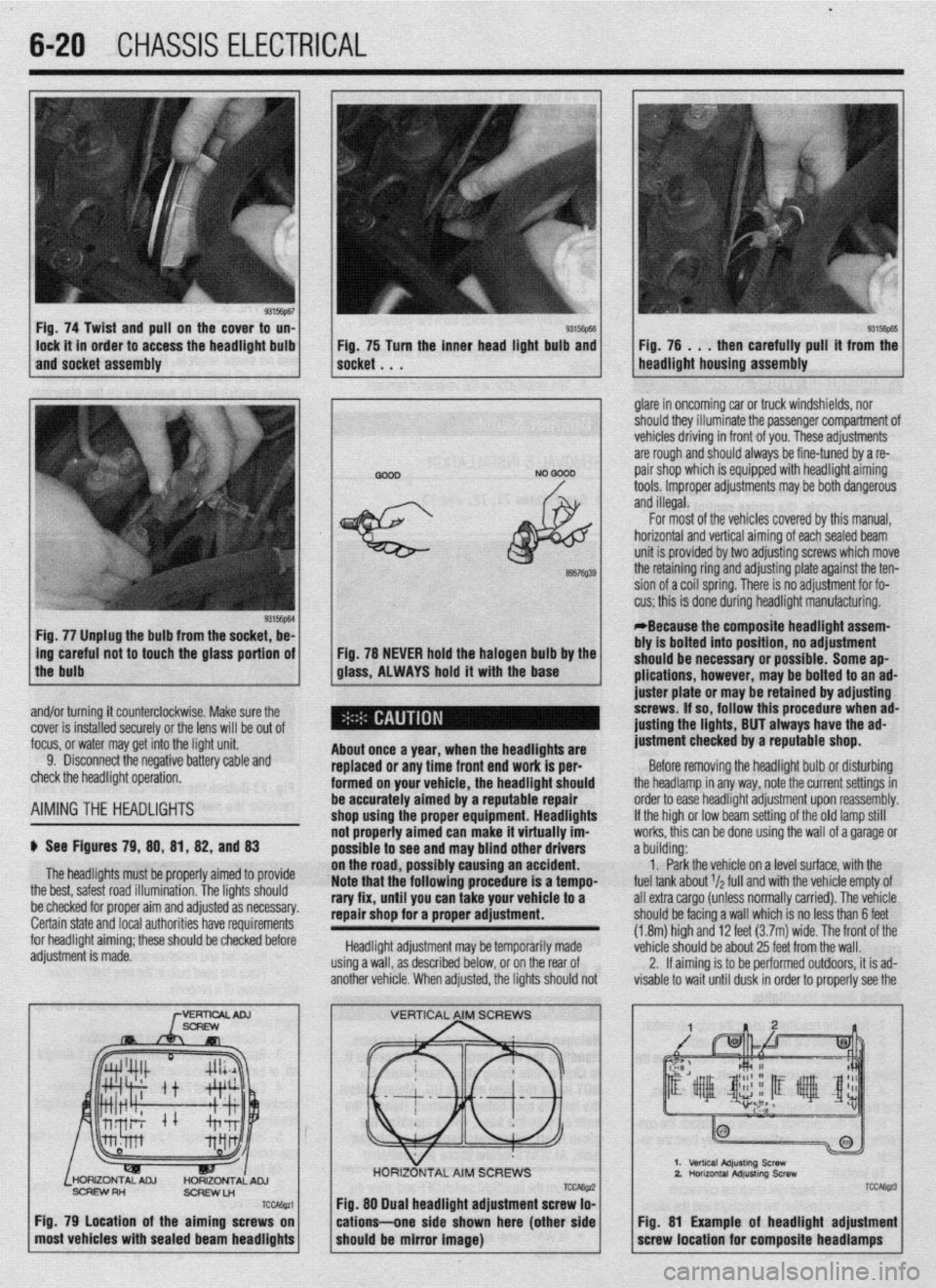
Fig. 74 Twist and pull on the cover to un-
lock it in order to access the headlight bulb
and socket assembly 93Mm Fig, 75 Turn the inner head light bulb and then carefully pull’ it from the
NO 0000 . glare in oncoming car or truck windshields, nor
should they illuminate the passenger compartment of
vehicles driving in front of you. These adjustments
are rough and should always be fine-tuned by a re-
pair shop which is equipped with headlight aiming
tools. Improper adjustments may be both dangerous
and illegal.
Fig. 77 Unplug the bulb from the socket, be-
L
ing careful not to touch the glass portion of
the bulb
I
6957Q39
Fig. 78 NEVER hold the halogen bulb by the
glass, ALWAYS hold it with the base
,
About once a year, when the headllgftts are
replaced or any time front end work is per-
formed on your vehicle, the headlight should
be accurately aimed by a reputable repair
shop uslng the proper equipment. Headlights
not properly aimed can make it virtually im-
possible to see ar Id may blind other drivers
ibly causing an accident.
Note that the’following procedure is a tempo-
rary fix, until you can take your vehicle to a
repair shop for a proper adjustment.
Headlight adjustment may be temporarily made
using a wall, as described below, or on the rear of
another vehicle. When adjusted, the lights should not For most of the vehicles covered by this manual,
horizontal and vertical aiming of eachsealed beam
unit is provided by two adjusting screws which move
the retaining ring and adjusting plate against the ten-
sion of a coil spring. There is no adjustment for fo-
cus; this is done during headlight manufacturing.
*Because the composite headlight assem-
bly is bolted into position, no adjustment
should be necessary or possible. Some ap-
plications, however, may be bolted to an ad-
juster plate or may be retained by adjusting
screws. If so, follow this procedure when ad-
@sting the lights, BUT always have the ad-
justment checked by a reputable shop.
Before removing the headlight bulb or disturbing
the headlamp in any way, note the current settings in
order to ease headlight adjustment upon reassembly.
If the high or low beam setting of the old lamp still
works, this can be done using the wall of a garage or
a building:
1. Park the vehicle on a level surface, with the
fuel tank about r/a full and with the vehicle empty of
all extra cargo (unless normally carried). The vehicle
should be facing a wall which is no less than 6 feet
(1.8m) high and 12 feet (3.7m) wide. The front of the
vehicle should be about 25 feet from the wall.
2. If aiming is to be performed outdoors, it is ad-
visable to wait until dusk in order to properly see the
% and/or turning it counterclockwise. Make sure the
cover is installed securely or the lens will be out of
focus, or water may get into the light unit.
9. Disconnect the negative battery cable and
check the headlight operation.
AIMINGTHE HEADLIGHTS
$ See Figures 79, 88, 81, 82, and 83
The headlights must be proper’ ’ ’ ’
the best, safest road illumination. ’ ’
ly armea IO provrae
The lights should
:.__1__1 __ - -___-_-. on the road, POSSI
be checked for proper aim and adfusreu as IlweSYdly. Certain state and local authorities have requirements
for headlight aiming; these should be checked before
adjustment is made.
SCFEWRH
ScFlEwLn
TCcAssa
Fig. 79 Location of the aiming screws on
most vehicles with sealed beam headlights
TCCAE@ Fig. 88 Dual headlight adjustment screw lo-
cations--one side shown here (other side
should be mirror image)
2.
TCC&z3
Fig. 81 Example of headlight adjustment
screw location for composite headlamps