1900 MITSUBISHI DIAMANTE four wheel drive
[x] Cancel search: four wheel drivePage 29 of 408
.
l-30 GENERAL'INFORMATIONAND MAINTENANCE
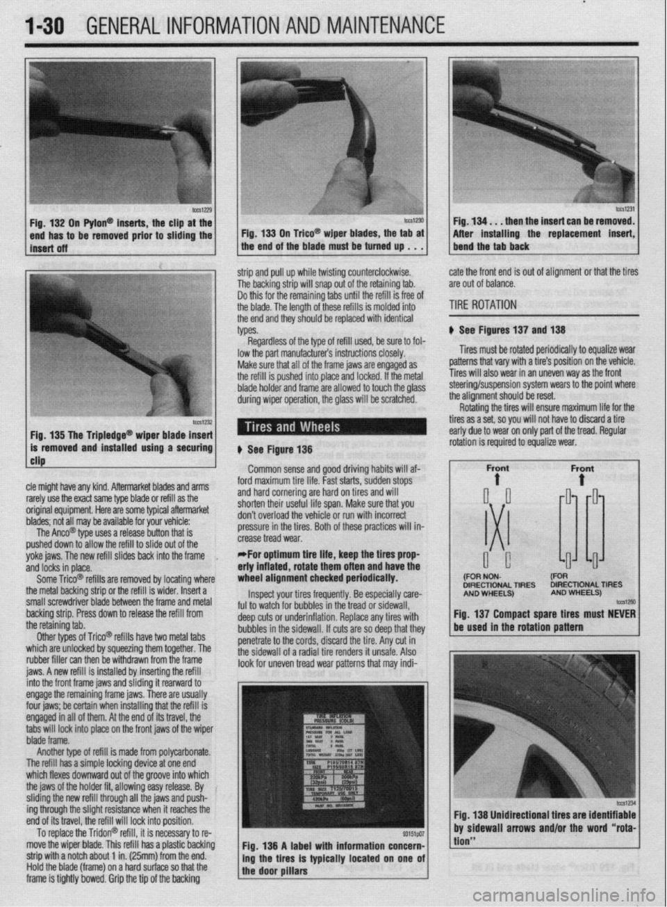
n Pylon@ inserts, the clip
be removed prior to siidi then the insert can be re
After installing the replacement
strip and pull up while twisting counterclockwise.
The backing strip will snap out of the retaining tab.
Do this for the remaining tabs until the refill is free of
the blade. The length of these refills is molded into
the end and they should be replaced with identical
types. cate the front end is out of alignment or that the tires
are out of balance.
TIRE ROTATION
# See Figures 137 and 138
Tires must be rotated periodically to equalize wear
patterns that vary with a tire’s position on the vehicle.
Tires will also wear in an uneven way as the front
1 Fin 1% Tha Trinlarlna@
cle might have any kind. Aftermarket blades and arms
rarely use the exact same type blade or refill as the
original equipment. Here are some typiel aftermarket
blades; not all may be available for your vehicle:
The Anco@ type uses a release button that is
pushed down to allow the refill to slide out of the
yoke jaws. The new refill slides back into the frame
,
and locks in place.
Some Trico@ refills are removed by locating where
the metal backing strip or the refill is wider. Insert a
small screwdriver blade between the frame and metal
backing strip. Press down to release the refill from
the retaining tab.
Other types of Trico@’ refills have two metal tabs
which are unlocked by squeezing them together. The
rubber filler can then be withdrawn from the frame
iaws. A new refill is installed bv insertina the refill lowed to touch the olass steering/suspension system wears to the point where
the alianment should be reset.
# See Figure 138
Common sense and good driving habits will af-
ford maximum tire life. Fast starts, sudden stops
and hard cornering are hard on tires and will
shorten their useful life span. Make sure that you
don’t overload the vehicle or run with incorrect
pressure in the tires. Both of these practices will in-
crease tread wear.
*For optimum tire life, keep the fires prop
eriy inflated, rotate them often and have the
wheel alignment checked periodically.
Inspect your tires frequently. Be especially care-
ful to watch for bubbles in the tread or sidewall,
deep cuts or underinflation. Replace any tires with
bubbles in the sidewall. If cuts are so deep that they
penetrate to the cords, discard the tire. Any cut in
the sidewall of a radial tire renders it unsafe. Also
look for uneven tread wear patterns that may indi- Rotating the tires will ensure maximum life for the
tires as a set, so you will not have to discard a tire
early due to wear on only part of the tread. Regular
DIRECTIONAL TIRES DIRECTIONAL TIRES
jnto the front frame jaws and &ding it rearward to
engage the remaining frame jaws. There are usually
four jaws; be certain when installing that the refill is
engaged in all of them. At the end of its travel, the
tabs will lock into place on the front jaws of the wiper
blade frame.
Another type of refill is made from polycarbonate.
The refill has a simple locking device at one end
which flexes downward out of the groove into which
the jaws of the holder fit, allowing easy release. By
sliding the new refill through all the jaws and push-
ing through the slight resistance when it reaches the
end of its travel, the refill will lock into position.
To replace the Tridon@ refill, it is necessary to re-
move the wiper blade. This refill has a plastic backing
strip with a notch about 1 in. (25mm) from the end.
Hold the blade (frame) on a hard surface so that the
frame is tightly bowed. Grip the tip of the backing Fig. 138 A label with information concern-
ing the tires is typically located on one of
the door pillars
tion”
Page 30 of 408
GENERALINFORMATIONAND MAlNTENANdE 1-31
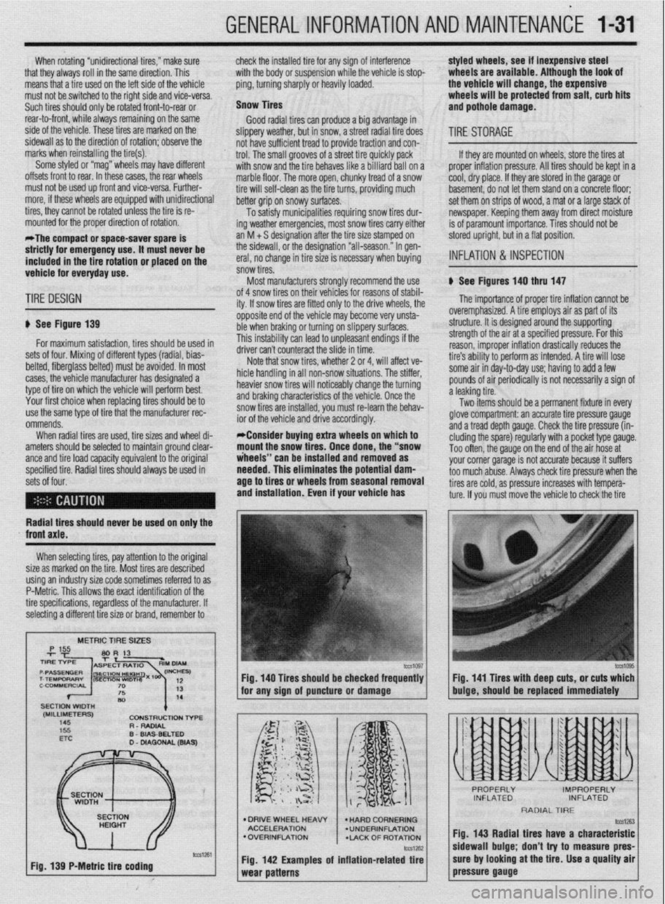
When rotating “unidirectional tires,” make sure
that they always roll in the same direction. This
means that a tire used on the left side of the vehicle
must not be switched to the right side and vice-versa.
Such tires should only be rotated front-to-rear or
rear-to-front, while always remaining on the same
side of the vehicle. These tires are marked on the
sidewall as to the direction of rotation; observe the
marks when reinstalling the tire(s).
Some styled or “mag” wheels may have different
offsets front to rear. In these cases, the rear wheels
must not be used up front and vice-versa. Further-
more, if these wheels are equipped with unidirectional
tires, they cannot be rotated unless the tire is re-
mounted for the proper direction of rotation.
*The compact or space-saver spare is
strictly for emergency use. it must never be
included in the tire rotation or placed on the
vehicle for everyday use. check the installed tire for any sign of interference
with the body or suspension while the vehicle is stop-
ping, turning sharply or heavily loaded.
Snow Tires
Good radial tires can produce a big advantage in
slippery weather, but in snow, a street radial tire does
not have sufficient tread to provide traction and con-
trol. The small grooves of a street tire quickly pack
with snow and the tire behaves like a billiard ball on a
marble floor, The more open, chunky tread of a snow
tire will self-clean as the tire turns, providing much
better grip on snowy surfaces.
To satisfy municipalities requiring snow tires dur-
ing weather emergencies, most snow tires carry either
an M + S designation after the tire size stamped on
the sidewall, or the designation “all-season.” In gen-
eral, no change in tire size is necessary when buying
snow tires.
Most manufacturers stronqlv recommend the use styled wheels, see if inexpensive steel
wheels are available, Although the look of
the vehicle will change, the expensive
wheels will be protected from salt, curb hits
and pothole damage.
TIRESTORAGE
If they are mounted on wheels, store the tires at
proper inflation pressure. All tires should be kept in a
cool, dry place. If they are stored in the garage or
basement, do not let them stand on a concrete floor;
set them on strips of wood, a mat or a large stack of
newspaper. Keeping them away from direct moisture
is of paramount importance. Tires should not be
stored upright, but in a flat position.
INFLATION & INSPECTION
b See Figures 140 thru 147
TIRE DESIGN
p See Figure 139
for maximum satisfaction, tires should be used in
sets of four. Mixing of different types (radial, bias-
belted, fiberglass belted) must be avoided. In most
cases, the vehicle manufacturer has designated a
type of tire on which the vehicle will perform best.
Your first choice when replacing tires should be to
use the same type of tire that the manufacturer rec-
ommends.
When radial tires are used, tire sizes and wheel di-
ameters should be selected to maintain ground clear-
ante and tire load caoacitv eauivalent to the oriainal
specified tire. Radial tiresshould always be used in
sets of four. of 4 snow tires on their
lehicies for reasons of stabil-
ity. If snow tires are fitter
1 only to the drive wheels, the
opposite end of the vehil cle may become very unsta-
ble when braking or turn
ring on slippery surfaces.
This instability can lead to unpleasant endings if the
A*:,,“- r-..l, ^_.. ..& ^_^^, &I.
UIIVU MII I LUUII~~MLL iue slide in time.
Note that snow tires, whether 2 or 4, will affect ve-
hicle handling in all non-snow situations. The stiffer,
heavier snow tires will noticeably change the turning
and braking characteristics of the vehicle. Once the
snow tires are installed, you must re-learn the behav-
ior of the vehicle and drive accordingly.
*Consider buying extra wheels on which to
mount the snow tires. Once done, the “snow
iheeis” can be installed and removed as
needed. This eliminates the potential
dam- age to tires or wheels from seasonal removal
and installation. Even if your vehicle has
lb The importance of proper tire inflation cannot be
overemphasized. A tire employs air as part of its
structure. It is designed around the supporting
strength of the air at a specified pressure. For this
reason, improper inflation drastically reduces the
tire’s ability to perform as intended. A tire will lose
some air in day-to-day use; having to add a few
pounds of air periodically is not necessarily a sign of
a leaking tire.
Two items should be a permanent fixture in every
glove compartment: an accurate tire pressure gauge
and a tread depth gauge. Check the tire pressure (in-
eluding the spare) regularly with a pocket type gauge.
Too often, the gauge on the end of the air hose at
vnr rr corner narane is not accurate because it suffers
~rs check tire oressure when the
Radial tires should never be used on only the
XI I._.
‘-’ --“‘“’ J s too much abuse. Alwa!
tires are cold, as pressure increases with tempera-
ture. If you must move the vehicle to check the tire
front axle.
When selecting tires, pay attention to the original
size as marked on the tire. Most tires are described
using an industry size code sometimes referred to as
P-Metric. This allows the exact identification of the
tire specifications, regardless of the manufacturer. If
selecting a different tire size or brand, remember to
METRIC TIRE SIZES
(MILLIMETERS)
145 CDNStRUCtlDN l-6-E
R - RADIAL
D
WA9
Fig. 139 P-Metric tire coding Fig. 140 Tires should be checked frequently
I I Fig. 141 Tires with deep cuts, or cuts which
for any sion of auncture or damaoe
buioe, should be replaced immediately
l DRIVE WHEEL HEAW
ACCELERATION
l OVERINFLATION
*LACK OF ROTATION
Fig. 142 Examples of inflation-related tire
RADIAL TIRE
fig. 143 Radial tires have a characteristic
sidewall bulge; don’t try to measure pres-
sure by looking at the tire. Use a quality air
pressure gauge
Page 311 of 408
8116 SUSPENSION AND STEERING
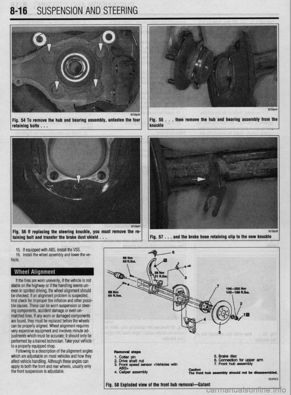
Fig. 54 To remove the hub and bearing assembly, unfasten the four Fig. 55 . . . then remove the hub and bearing assembly from the
retaining bolts . . . knuckle
Fig, 56 If replacing the steering knuckle, you must remove the re-
taining bolt and transfer the brake dust shield . . .
15. If equipped with ABS, install the VSS.
16. Install the wheel assembly and lower the ve-
hicle.
If the tires are worn unevenly, if the vehicle is not
stable on the highway or if the handling seems un-
even in spirited driving, the wheel alignment should
be checked. If an alignment problem is suspected,
first check for improper tire inflation and other possi-
ble causes. These can be worn suspension or steer-
ing components, accident damage or even un-
matched tires. If any worn or damaged components
are found, they must be replaced before the wheels
can be properly aligned. Wheel alignment requires
very expensive equipment and involves minute ad-
justments which must be accurate; it should only be
performed by a trained technician. Take your vehicle
to a properly equipped shop.
Following is a description of the alignment angles
which are adjustable on most vehicles and how they
affect vehicle handling. Although these angles can
apply to both the front and rear wheels, usually only
the front suspension is adjustable.
5.BrakediW
2. Drive shafl nut &collnectionfciflJpperarm
3. Frc-rc,speed fiensor cvehides with 7. Front hub assembly
4. Caliper asWmbly cauuen
nlcrfonthubaMmbly~natbrrliurr#n61ed.
Page 322 of 408
8-26 SUSPENSION AND STEERING
torqued to specifications. The wheel bearings are
sealed units and are not adjustable. If defective, re-
placement is the only option.
REMOVAL &INSTALLATION
Mirage
7996-92 MODELS
1. Raise the vehicle and support safely.
2. Remove the tire and wheel assembly.
3. If equipped with rear disc brakes, remove the
caliper from the disc and remove the brake disc.
4. Remove the dust cap and bearing nut. Do not
use an air gun to remove the nut.
5. Remove the outer wheel bearing.
6. Remove the drum and/or axle hub with the
inner wheel bearing and the grease seal.
7. Remove the grease seal and remove the inner
bearing.
To install: 8. Lubricate the inner bearing and install to the
drum or hub.
9. Install a new grease seal.
10. To determine if the self-locking nut is
reusable:
a. Screw in the self-locking nut until about
0.07-0.11 in. (2-3mm) of thread is visible under
the nut.
b. Measure the torque required to turn the
self-locking nut counterclockwise.
c. The lowest allowable torque is 48 inch Ibs.
(6 Nm). If the measured torque is less than the
specification, replace the nut.
11. Install the drum and/or hub to the vehicle.
12. Lubricate and install the outer wheel bearing
to the spindle.
13. Tighten the self-locking nut to 108-145 ft.
Ibs. (150-200 Nm).
14. Set up a dial indicator and measure the end-
play while moving the hub or drum in and out. If the
endplay exceeds 0.008 in. (0.002mm) retorque the
nut. If still beyond the limit, replace the bearings.
15. Install the grease cap and wheel assembly.
7993-60 MODELS
*Never disassemble the rear hub bearing.
The wheel bearing is serviced by replace-
ment of the hub.
1. If equipped with ABS, remove the wheel
speed sensor.
2. Raise and safely support the vehicle.
3. Remove the rear wheel.
4. Remove the caliper and brake disc or brake
drum.
5. Remove the dust cap and flange nut.
6. Remove the rear hub assembly.
To install: 7. Install the rear hub assembly using a new
flange nut. Tighten the flange nut to 130 ft. Ibs. (180
Nm).
8. install the dust cap.
9. Install the wheel speed sensor if removed.
The air gap should be 0.012-0.035 in. (0.3-0.9mm).
10. Install the brake disc and caliper, or brake
drum.
11. Install the rear wheel assembly and lower the
vehicle to the floor.
1990-93 Galant
DRUM BRAKE VEHICLES
1. Raise the vehicle and support it safely.
2. Remove the wheel and tire assemblies.
3. Remove the grease cap and the hub nut.
4. Remove the brake drum. The outer bearing
will fall out while the drum is coming off. Do not drop
it. Remove the hub and rotor assembly.
5. Pry out and discard the oil seal.
6. Remove the inner bearing.
*Check the bearing races. If any scoring,
heat checking or damage is noted, they
should be replaced. When bearing or races
need replacement, replace them as a set.
7. If the bearings and races are to be replaced,
drive out the race with a brass drift.
To install: 8. Before installing new races, coat them with
wheel bearing grease. Drive into place with proper
size driver. Make sure they are fully seated.
9. Thoroughly pack the bearings and lubricate
the hubs with wheel bearing grease. Install the inner
bearing and coat the lip and rim of the grease seal
with grease. Drive the seal into place with a seal dri-
ver.
10. Install the drum assembly on the axle.
11, Lubricate and install the outer wheel bearing,
washer and nut. To properly adjust the wheel bearing
preload:
a. Tighten the wheel bearing nut to 20 ft. Ibs.
(27 Nm) while rotating the drum.
b. Back off the adjusting nut to remove the
preload, then tighten it to 7 ft. Ibs. (10 Nm).
c. Install the nut lock and a new cotter pin.
12. Install the wheel and lower the vehicle.
O/SC BRAKE VEHICLES
1. Raise the vehicle and support safely.
2. Remove the tire and wheel assembly.
3. Remove the bolt(s) holding the speed sensor
bracket to the knuckle and remove the assembly from
the vehicle.
The speed sensor has a pole piece projecting
from it. This exposed tip must be protected
from impact or scratches. Do not allow the
oole oiece to contact the toothed wheel dur-
in0 removal or installation.
4. Remove the caliper from the brake disc and
suspend with a wire.
5. Remove the brake rotor.
6. Remove the grease cap, locking nut and
tongued washer.
7. Remove the rear hub and bearing assembly.
*The rear hub assembly can not be disas-
sembled. If bearing replacement is required,
replace the assembly as a unit.
8. If replacing the hub assembly, remove the
two bolts securing the speed sensor ring to the hub.
To install: 9. Install the speed sensor to the hub and bear-
ing assembly. Tighten the mounting bolts to 8 ft. Ibs.
(11 Nm). 10. Install the hub and bearing assembly to the
axle shaft.
11, Install the tongued washer and a new locking
nut. Tighten the locknut to 144-188 ft. Ibs. (200-260
Nm). Once the locknut has been properly torqued,
crimp the nut flange over the slot in the spindle, and
install the grease cap.
12. Install the brake caliper and rotor.
13. Install the speed sensor and tighten the
mounting bolt to 8 ft. Ibs. (11 Nm).
14. Install the tire and wheel assembly.
Be sure to pump the brake pedal until it’s
firm, before moving vehicle.
1994-00 Galant
DRUM BRAKE VEHICLES
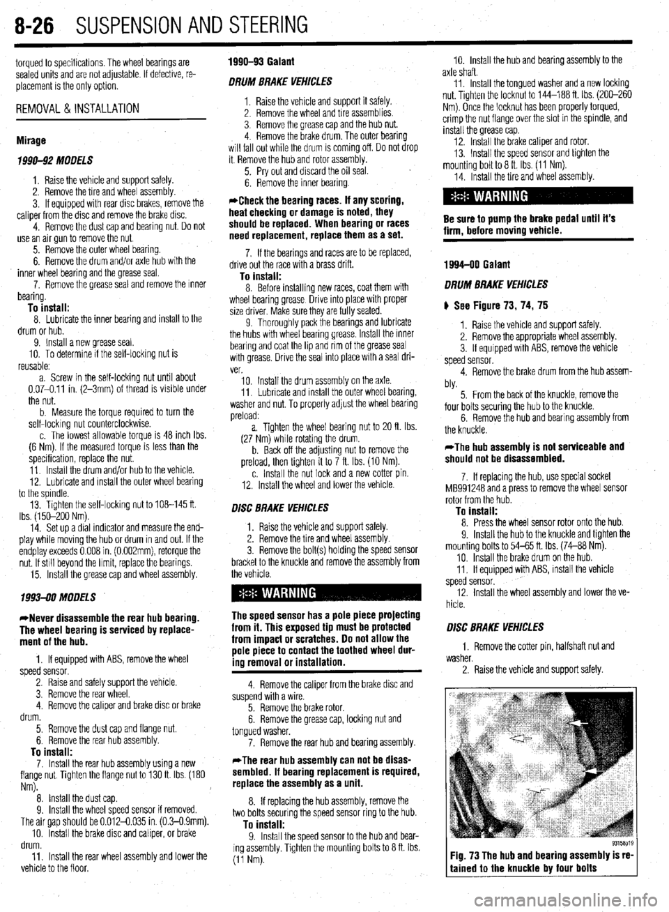
) See Figure 73, 74, 75
1. Raise the vehicle and support safely.
2. Remove the appropriate wheel assembly.
3. If equipped with ABS, remove the vehicle
speed sensor.
4. Remove the brake drum from the hub assem-
bly.
5. From the back of the knuckle, remove the
four bolts securing the hub to the knuckle.
6. Remove the hub and bearing assembly from
the knuckle.
*The hub assembly is not serviceable and
should not be disassembled.
7. If replacing the hub, use special socket
MB991248 and a press to remove the wheel sensor
rotor from the hub.
To install: 8. Press the wheel sensor rotor onto the hub.
9. Install the hub to the knuckle and tighten the
mounting bolts to 54-65 ft. Ibs. (74-88 Nm).
10. Install the brake drum on the hub.
11. If equipped with ABS, install the vehicle
speed sensor.
12. Install the wheel assembly and lower the ve-
hicle.
O/SC BRAKE VEHICLES
1. Remove the cotter pin, halfshaft nut and
washer.
2. Raise the vehicle and support safely.
Fig. 73 The hub and bearing assembly is re-
tained to the knuckle by four bolts
Page 331 of 408
SUSPENSION AND STEERING 8-35
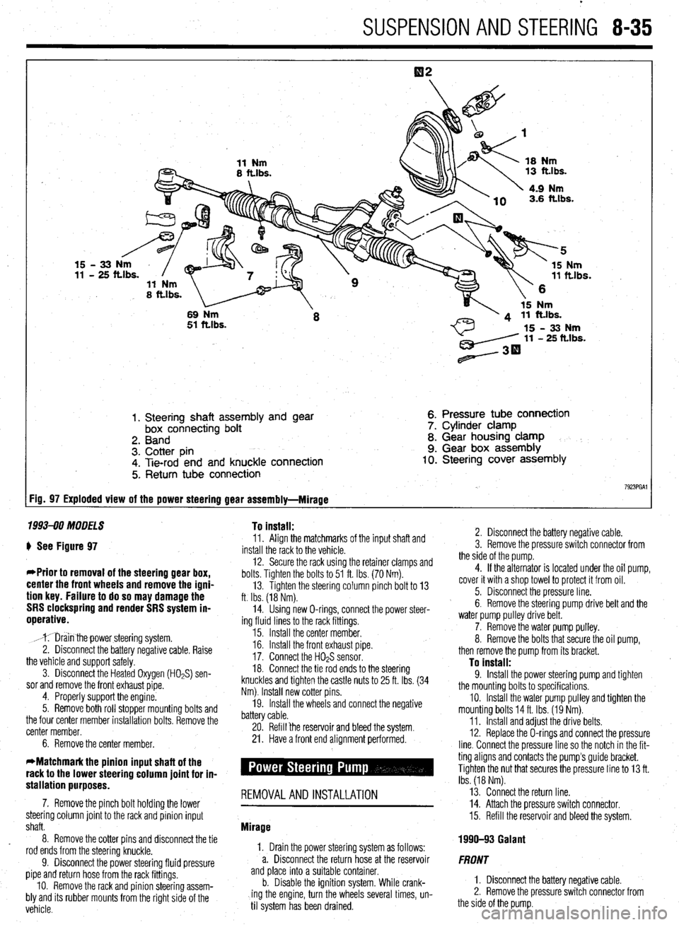
1. Steering shaft assembly and gear
box connecting bolt
2. Band
3. Cotter pin
4. Tie-rod end and knuckle connection
5. Return tube connection 6. Pressure tube connection
7. Cylinder clamp
8. Gear housing clamp
9. Gear box assembly 10. Steering cover assembly
7923PGAl FiD= 97 Exploded view of the power steering gear assembly-Mirage
1993-90 MODELS To install:
) See Figure 97
*Prior to removal of the steering gear box,
center the front wheels and remove the igni-
tion key. Failure to do so may damage the
SRS clockspring and render SRS system in-
operative.
,mr;iin thepower steering system.
2. Disconnect the battery negative cable. Raise
the vehicle and support safely.
3. Disconnect the Heated Oxygen (HOPS) sen-
sor and remove the front exhaust pipe.
4. Properly support the engine.
5. Remove both roll stopper mounting bolts and
the four center member installation bolts. Remove the
center member.
6. Remove the center member. 11. Align the matchmarks of the input shaft and
install the rack to the vehicle.
12. Secure the rack using the retainer clamps and
bolts. Tighten the bolts to 51 ft. Ibs. (70 Nm).
13. Tighten the steering column pinch bolt to 13
ft. Ibs. (18 Nm).
14. Using new O-rings, connect the power steer-
ing fluid lines to the rack fittings.
15. Install the center member.
16. Install the front exhaust pipe.
17. Connect the H02S sensor.
18. Connect the tie rod ends to the steering
knuckles and tighten the castle nuts to 25 ft. Ibs. (34
Nm). Install new cotter pins.
19. Install the wheels and connect the negative
battery cable.
20. Refill ‘the reservoir and bleed the system.
21. Have a front end alignment performed.
stallation purposes. -
7. Remove the pinch bolt holding the lower REMOVALANDINSTALLATION
steering column joint to the rack and pinion input
shaft.
8. Remove the cotter pins and disconnect the tie
rod ends from the steering knuckle.
9. Disconnect the power steering fluid pressure
pipe and return hose from the rack fittings.
IO. Remove the rack and pinion steering assem-
bly and its rubber mounts from the right side of the
vehicle. Mirage
1, Drain the power steering system as follows:
a. Disconnect the return hose at the reservoir
and place into a suitable container.
b. Disable the ignition system. While crank-
ing the engine, turn the wheels several times, un-
til system has been drained. 2. Disconnect the battery negative cable.
3. Remove the pressure switch connector from
the side of the pump.
4. If the alternator is located under the oil pump,
cover it with a shop towel to protect it from oil.
5. Disconnect the pressure line.
6. Remove the steering pump drive belt and the
water pump pulley drive belt.
7. Remove the water pump pulley.
8. Remove the bolts that secure the oil pump,
then remove the pump from its bracket.
To install: 9. Install the power steering pump and tighten
the mounting bolts to specifications.
IO. Install the water pump pulley and tighten the
mounting bolts 14 ft. Ibs. (19 Nm).
11. Install and adjust the drive belts.
12. Replace the O-rings and connect the pressure
line. Connect the pressure line so the notch in the fit-
ting aligns and contacts the pump’s guide bracket.
Tighten the nut that secures the pressure line to 13 ft.
Ibs. (18 Nm).
13. Connect the return line.
14. Attach the pressure switch connector.
15. Refill the reservoir and bleed the system.
1990-93 Galant
FRONT
1. Disconnect the battery negative cable.
2. Remove the pressure switch connector from
the side of the pump.
Page 385 of 408
I TROUBLESHOOTING II-3
Condition Section/hem Number
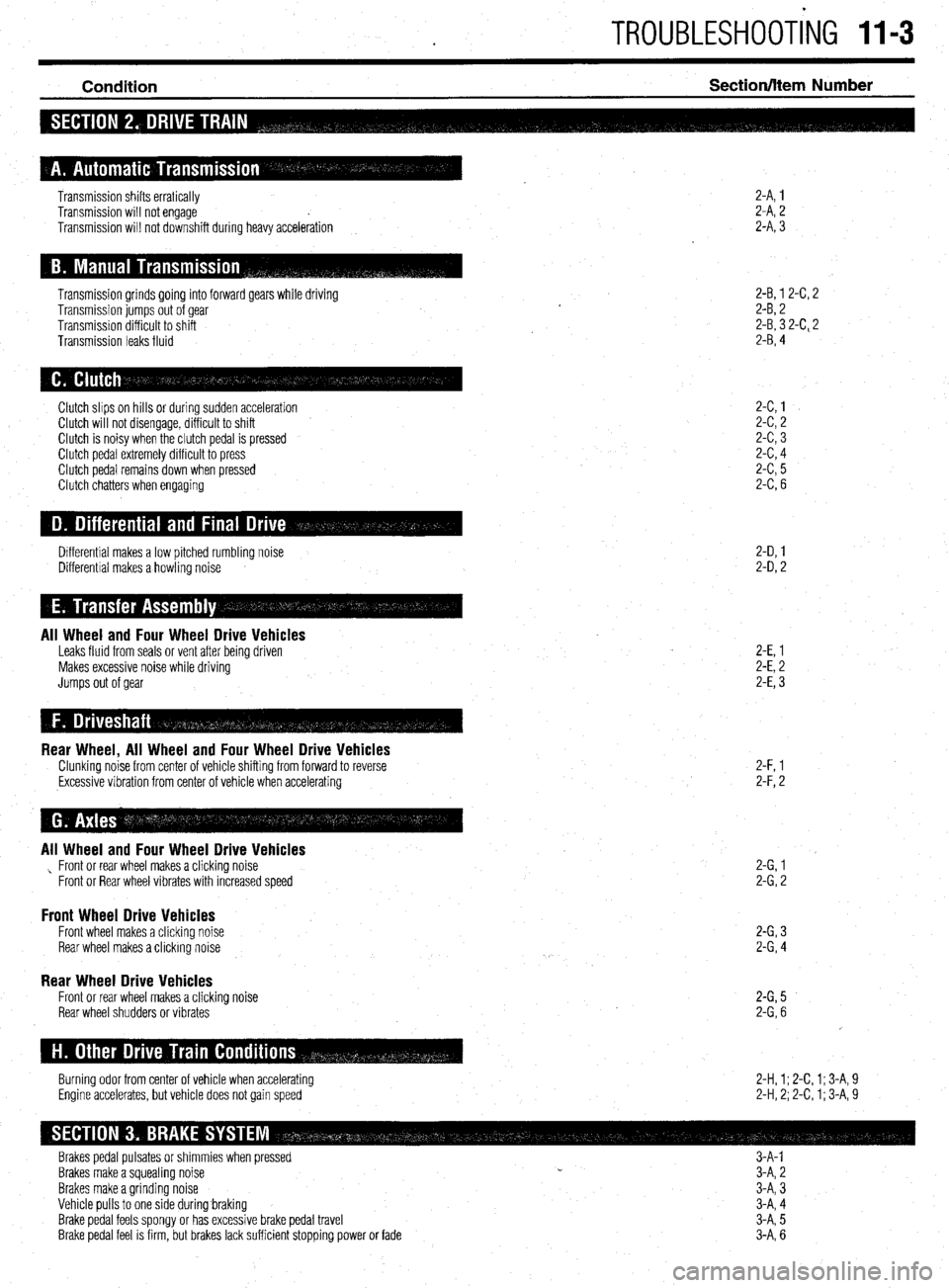
2-A, 1
2-A, 2
2-A, 3 Transmission shifts erratically
Transmission will not engage
Transmission will not downshift during heavy acceleration
Transmission grinds going into forward gears while driving
Transmission jumps out of gear
Transmission difficult to shift
Transmission leaks fluid 2-B, 1 2-C, 2
2-B, 2
2-B, 3 2-C, 2
2-B, 4
2-C,l
2-c,2
2-c,3
2-c,4
2-c,5
2-C,6 Clutch slips on hills or during sudden acceleration
Clutch will not disengage, difficult to shift
Clutch is noisy when the clutch pedal is pressed
Clutch pedal extremely difficult to press
Clutch pedal remains down when pressed
Clutch chatters when engaging
2-D, 1
2-D, 2 Differential makes a low pitched rumbling noise
Differential makes a howling noise
All Wheel and Four Wheel Drive Vehicles Leaks fluid from seals or vent after being driven
Makes excessive noise while driving
Jumps out of gear 2-E, 1
2-E, 2
2-E, 3
Rear Wheel, All Wheel and Four Wheel Drive Vehicles Clunking noise from center of vehicle shifting from forward to reverse
,Excessive vibration from center of vehicle when accelerating 2-F, l
2-F,2
All Wheel and Four Wheel Drive Vehicles , Front or rear wheel makes a clicking noise
Front or Rear wheel vibrates with increased speed 2-G,l
2-G,2
Front Wheel Drive Vehicles Front wheel makes a clicking noise
Rear wheel makes a clicking noise 2-G,3
2-G,4
Rear Wheel Drive Vehicles Front or rear wheel makes a clicking
Rear wheel shudders or vibrates noise 2-G,5
2-G,6
2-H, 1; 2-C, 1; 3-A, 9
2-H, 2; 2-C, 1; 3-A, 9 Burning odor from center of vehicle when accelerating
Engine accelerates, but vehicle does not gain speed
Brakes pedal pulsates or shimmies when pressed 3-A-l
Brakes make a squealing noise CI
3-A, 2
Brakes make a grinding noise
Vehicle pulls to one side during.braking
Brake pedal feels spongy or has excessive brake pedal travel
Brake pedal feel is firm, but brakes lack sufficient stopping power or fade 3-A, 3
3-A, 4
3-A, 5
3-A, 6
Page 386 of 408
11-4 TROUBLESHOOTING
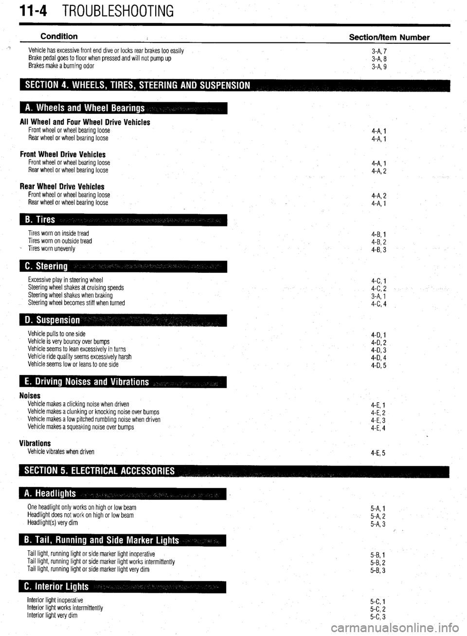
Condition
2 Section/Item Number ^i Vehicle has excessive front end dive or locks rear brakes too easily
3-A, 7
Brake pedal goes to floor when pressed and will not pump up
3-A, 8
Brakes make a burning odor
3-A, 9
All Wheel and Four Wheel Drive Vehicles Front wheel or wheel bearing loose
Rear wheel or wheel bearingloose
Front Wheel Drive Vehicles Front wheel or wheel bearing loose
Rear wheel or wheel bearing loose 4-A. 1
4-A: 1
4-A, 1
4-A, 2
Rear Wheel Drive Vehicles Front wheel or wheel bearing loose
Rear wheel or wheel bearing loose 4-A, 2
4-A, 1
Tires worn on inside tread
Tires worn on outside tread
s Tires worn unevenly 4-B, 1
4-B, 2
4-B, 3
Excessive play in steering wheel
Steering wheel shakes at cruising speeds
Steering wheel shakes when braking
Steering wheel becomes stiff when turned 4-c, 1
4-c, 2
3-A, 1
4-c, 4
Vehicle pulls to one side
Vehicle is very bouncy over bumps
Vehicle seems to lean excessively in turns
Vehicle ride quality seems excessively harsh
Vehicle seems low or leans to one side 4-D 1
4-D, 2
4-D, 3
4-D, 4
4-D, 5
Noises Vehicle makes a clicking noise when driven
Vehicle makes a clunking or knocking noise over bumps
Vehicle makes a low pitched rumbling noise when driven
Vehicle makes a squeaking noise over bumps
Vibrations Vehicle vibrates when driven 4-E, 1
4-E, 2
4-E, 3
4-E, 4
4-E, 5
One headlight only works on high or low beam
Headlight does not work on high or low beam
Headlight(s) very dim
Tail light, running light or side marker light inoperative
Tail light, running light or side marker light works intermittently
Tail light, running light or side marker light very dim 5-A, 1
5-A, 2
5-A, 3
/ .
5-B, 1
5-B, 2
5-B, 3
Interior light inoperative
Interior light works intermittently
Interior light very dim 5-c, 1
5-c, 2
5-c, 3
Page 392 of 408
II-10 TROUBLESHOOTING
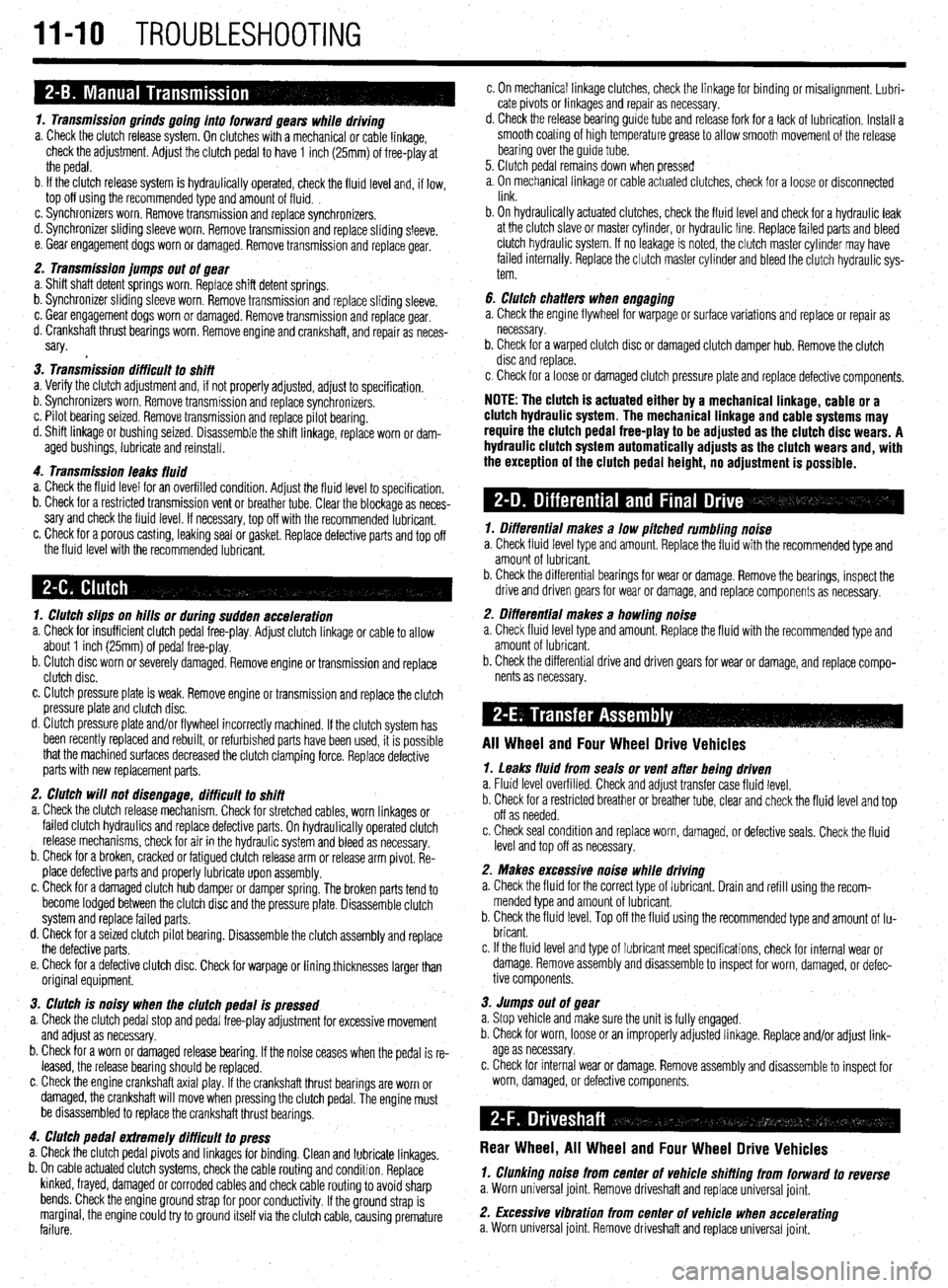
1. Transmission grinds going into forward gears while driving
a. Check the clutch release system. On clutches with a mechanical or cable linkage,
check the adjustment. Adjust the clutch pedal to have 1 inch (25mm) of free-play at
the pedal.
b. If the clutch release system is hydraulically operated, check the fluid level and, if low,
top off using the recommended type and amount of fluid. ,
c. Synchronizers worn. Remove transmission and replace synchronizers.
d. Synchronizer sliding sleeve worn. Remove transmission and replace sliding sleeve.
e. Gear engagement dogs worn or damaged. Remove transmission and replace gear.
2. Transmission jumps out of gear
a. Shift shaft detent springs worn. Replace shift detent springs.
b. Synchronizer sliding sleeve worn. Remove transmission and replace sliding sleeve.
c. Gear engagement dogs worn or damaged. Remove transmission and replace gear.
d. Crankshaft thrust bearings worn. Remove engine and crankshaft, and repair as neces-
sary.
3. Transmission difficult to shift
a. Verify the clutch adjustment and, if not properly adjusted, adjust to specification.
b. Synchronizers worn. Remove transmission and replace synchronizers.
c. Pilot bearing seized. Remove transmission and replace pilot bearing.
d. Shift linkage or bushing seized. Disassemble the shift linkage, replace worn or dam-
aged bushings, lubricate and reinstall.
4. Transmission leaks fluid
a. Check the fluid level for an overfilled condition. Adjust the fluid level to specification.
b. Check for a restricted transmission vent or breather tube. Clear the blockage as neces-
sary and check the fluid level. If necessary, top off with the recommended lubricant.
c. Check for a porous casting, leaking seal or gasket. Replace defective parts and top off
the fluid level with the recommended lubricant.
1. Clutch slips on hills or during sudden acceleration
a. Check for insufficient clutch pedal free-play. Adjust clutch linkage or cable to allow
about 1 inch (25mm) of pedal free-play.
b. Clutch disc worn or severely damaged. Remove engine or transmission and replace
clutch disc.
c. Clutch pressure plate is weak. Remove engine or transmission and replace the clutch
pressure plate and clutch disc.
d. Clutch pressure plate and/or flywheel incorrectly machined. If the clutch system has
been recently replaced and rebuilt, or refurbished parts have been used, it is possible
that the machined surfaces decreased the clutch clamping force. Replace defective
parts with new replacement parts.
2. Clutch will not disengage, difficult to shift
a. Check the clutch release mechanism. Check for stretched cables, worn linkages or
failed clutch hydraulics and replace defective parts. On hydraulically operated clutch
release mechanisms, check for air in the hydraulic system and bleed as necessary.
b. Check for a broken, cracked or fatigued clutch release arm or release arm pivot. Re-
place defective parts and properly lubricate upon assembly.
c. Check for a damaged clutch hub damper or damper spring. The broken parts tend to
become lodged between the clutch disc and the pressure plate. Disassemble clutch
system and replace failed parts.
d. Check for a seized clutch pilot bearing. Disassemble the clutch assembly and replace
the defective parts.
e. Check for a defective clutch disc. Check for warpage or liningthicknesses larger than
original equipment.
3. Clutch is noisy when the clutch pedal is pressed
a. Check the clutch pedal stop and pedal free-play adjustment for excessive movement
and adjust as necessary.
b. Check for a worn or damaged release bearing. If the noise ceases when the pedal is re-
leased, the release bearing should be replaced.
c. Check the engine crankshaft axial play. If the crankshaft thrust bearings are worn or
damaged, the crankshaft will move when pressing the clutch pedal. The engine must
be disassembled to replace the crankshaft thrust bearings.
4. Clutch pedal extremely difficult to press
a. Check the clutch pedal pivots and linkages for binding. Clean and lubricate linkages.
b. On cable actuated clutch systems, check the cable routing and condition. Replace
kinked, frayed, damaged or corroded cables and check cable routing to avoid sharp
bends. Check the engine ground strap for poor conductivity. If the ground strap is
marginal, the engine could try to ground itself via the clutch cable, causing premature
failure. c. On mechanical linkage clutches, check the linkage for binding or misalignment. Lubri-
cate pivots or linkages and repair as necessary.
d. Check the release bearing guide tube and release fork for a lack of lubrication. Install a
smooth coating of high temperature grease to allow smooth movement of the release
bearing over the guide tube.
5. Clutch pedal remains down when pressed
a, On mechanical linkage or cable actuated clutches, check for a loose or disconnected
link.
b. On hydraulically actuated clutches, check the fluid level and check for a hydraulic leak
at the clutch slave or master cylinder, or hydraulic line. Replace failed parts and bleed
clutch hydraulic system. If no leakage is noted, the clutch master cylinder may have
failed internally. Replace the clutch master cylinder and bleed the clutch hydraulic sys-
tem.
6. clutch chatters when engaging
a. Check the engine flywheel for warpage or surface variations and replace or repair as
necessary.
b. Check for a warped clutch disc or damaged clutch damper hub. Remove the clutch
disc and replace.
c. Check for a loose or damaged clutch pressure plate and replace defective components.
NOTE: The clutch is actuated either by a mechanical linkage, cable or a
clutch hydraulic system. The mechanical linkage and cable systems may
require the clutch pedal free-play to be adjusted as the clutch disc wears. A
hydraulic clutch system automatically adjusts as the clutch wears and, with
the exception of the clutch pedal height, no adjustment is possible.
1. Differential makes a low pitched rumbling noise
a. Check fluid level type and amount. Replace the fluid with the recommended type and
amount of lubricant.
b. Check the differential bearings for wear or damage. Remove the bearings, inspect the
drive and driven gears for wear or damage, and replace components as necessary.
2. Differential makes a howling noise
a. Check fluid level type and amount. Replace the fluid with the recommended type and
amount of lubricant.
b. Check the differential drive and driven gears for wear or damage, and replace compo-
nents as necessary.
All Wheel and Four Wheel Drive Vehicles
1. Leaks fluid from seals or vent after being driven
a. Fluid level overfilled. Check and adjust transfer case fluid level.
b. Check for a restricted breather or breather tube, clear and check the fluid level and top
off as needed.
c. Check seal condition and replace worn, damaged, or defective seals. Check the fluid
level and top off as necessary.
2. Makes excessive noise while driving
a. Check the fluid for the correct type of lubricant. Drain and refill using the recom-
mended type and amount of lubricant.
b. Check the fluid level. Top off the fluid using the recommended type and amount of lu-
bricant.
c. If the fluid level and type of lubricant meet specifications, check for internal wear or
damage. Remove assembly and disassemble to inspect for worn, damaged, or defec-
tive components.
3. Jumps out of gear
a. Stop vehicle and make sure the unit is fully engaged.
b. Check for worn, loose or an improperly adjusted linkage. Replace and/or adjust link-
age as necessary.
c. Check for internal wear or damage. Remove assembly and disassemble to inspect for
worn, damaged, or defective components.
Rear Wheel, All Wheel and Four Wheel Drive Vehicles
1. Clunking noise from center of Vehicle shifting from forward to reverse
a. Worn universal joint. Remove driveshaft and replace universal joint.
2. Excessive vibration from center of vehicle when accelerating
a. Worn universal joint. Remove driveshaft and replace universal joint.