1900 MITSUBISHI DIAMANTE steering wheel
[x] Cancel search: steering wheelPage 29 of 408
.
l-30 GENERAL'INFORMATIONAND MAINTENANCE
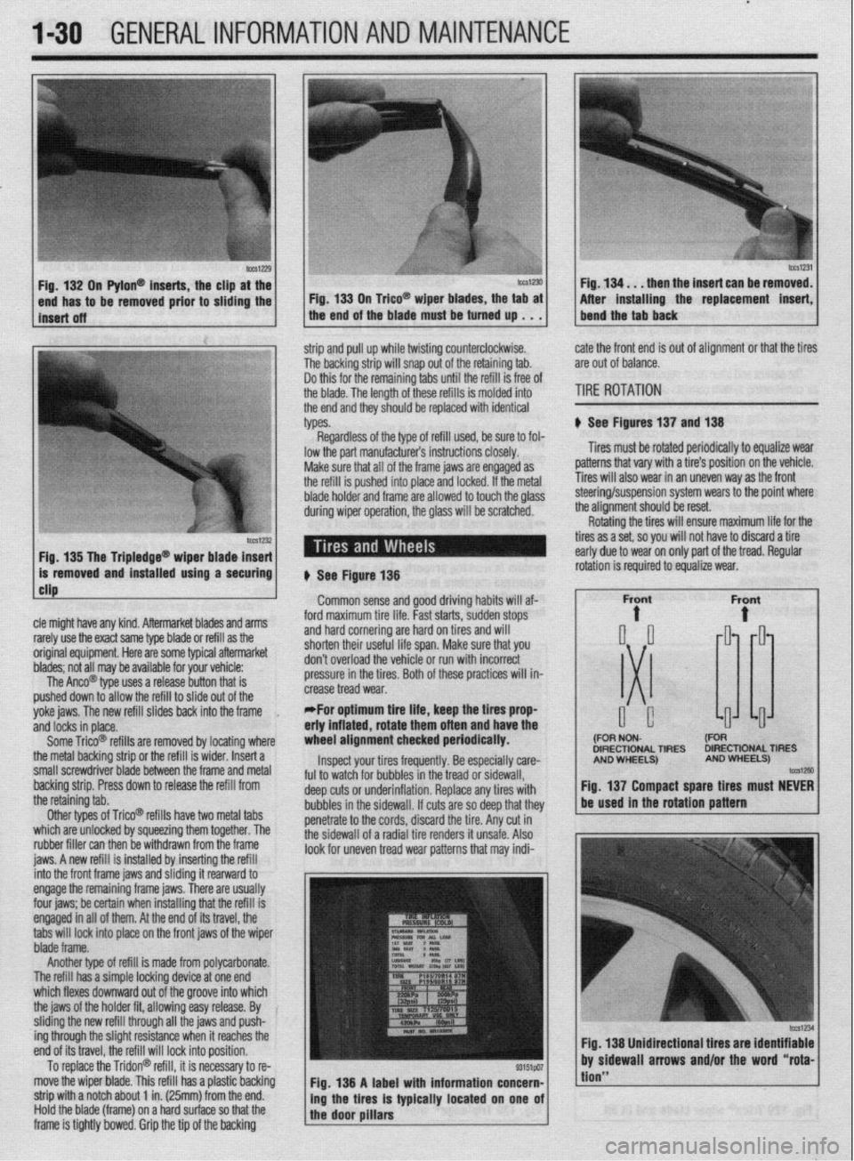
n Pylon@ inserts, the clip
be removed prior to siidi then the insert can be re
After installing the replacement
strip and pull up while twisting counterclockwise.
The backing strip will snap out of the retaining tab.
Do this for the remaining tabs until the refill is free of
the blade. The length of these refills is molded into
the end and they should be replaced with identical
types. cate the front end is out of alignment or that the tires
are out of balance.
TIRE ROTATION
# See Figures 137 and 138
Tires must be rotated periodically to equalize wear
patterns that vary with a tire’s position on the vehicle.
Tires will also wear in an uneven way as the front
1 Fin 1% Tha Trinlarlna@
cle might have any kind. Aftermarket blades and arms
rarely use the exact same type blade or refill as the
original equipment. Here are some typiel aftermarket
blades; not all may be available for your vehicle:
The Anco@ type uses a release button that is
pushed down to allow the refill to slide out of the
yoke jaws. The new refill slides back into the frame
,
and locks in place.
Some Trico@ refills are removed by locating where
the metal backing strip or the refill is wider. Insert a
small screwdriver blade between the frame and metal
backing strip. Press down to release the refill from
the retaining tab.
Other types of Trico@’ refills have two metal tabs
which are unlocked by squeezing them together. The
rubber filler can then be withdrawn from the frame
iaws. A new refill is installed bv insertina the refill lowed to touch the olass steering/suspension system wears to the point where
the alianment should be reset.
# See Figure 138
Common sense and good driving habits will af-
ford maximum tire life. Fast starts, sudden stops
and hard cornering are hard on tires and will
shorten their useful life span. Make sure that you
don’t overload the vehicle or run with incorrect
pressure in the tires. Both of these practices will in-
crease tread wear.
*For optimum tire life, keep the fires prop
eriy inflated, rotate them often and have the
wheel alignment checked periodically.
Inspect your tires frequently. Be especially care-
ful to watch for bubbles in the tread or sidewall,
deep cuts or underinflation. Replace any tires with
bubbles in the sidewall. If cuts are so deep that they
penetrate to the cords, discard the tire. Any cut in
the sidewall of a radial tire renders it unsafe. Also
look for uneven tread wear patterns that may indi- Rotating the tires will ensure maximum life for the
tires as a set, so you will not have to discard a tire
early due to wear on only part of the tread. Regular
DIRECTIONAL TIRES DIRECTIONAL TIRES
jnto the front frame jaws and &ding it rearward to
engage the remaining frame jaws. There are usually
four jaws; be certain when installing that the refill is
engaged in all of them. At the end of its travel, the
tabs will lock into place on the front jaws of the wiper
blade frame.
Another type of refill is made from polycarbonate.
The refill has a simple locking device at one end
which flexes downward out of the groove into which
the jaws of the holder fit, allowing easy release. By
sliding the new refill through all the jaws and push-
ing through the slight resistance when it reaches the
end of its travel, the refill will lock into position.
To replace the Tridon@ refill, it is necessary to re-
move the wiper blade. This refill has a plastic backing
strip with a notch about 1 in. (25mm) from the end.
Hold the blade (frame) on a hard surface so that the
frame is tightly bowed. Grip the tip of the backing Fig. 138 A label with information concern-
ing the tires is typically located on one of
the door pillars
tion”
Page 42 of 408
GENERALINFORMATIONAND MAINTENANCE l-43
l Special car washing detergent is the best to
use. Liquid dishwashing detergent can remove wax
and leave the car’s paint unprotected and in addition
some liquid detergents contains abrasives which can
scratch the paint.
l Bird droppings should be removed from the
paintwork as soon as possible, otherwise the finish
may be permanently stained.
When the car is driven immediately after be-
ing washed, apply the brakes several times
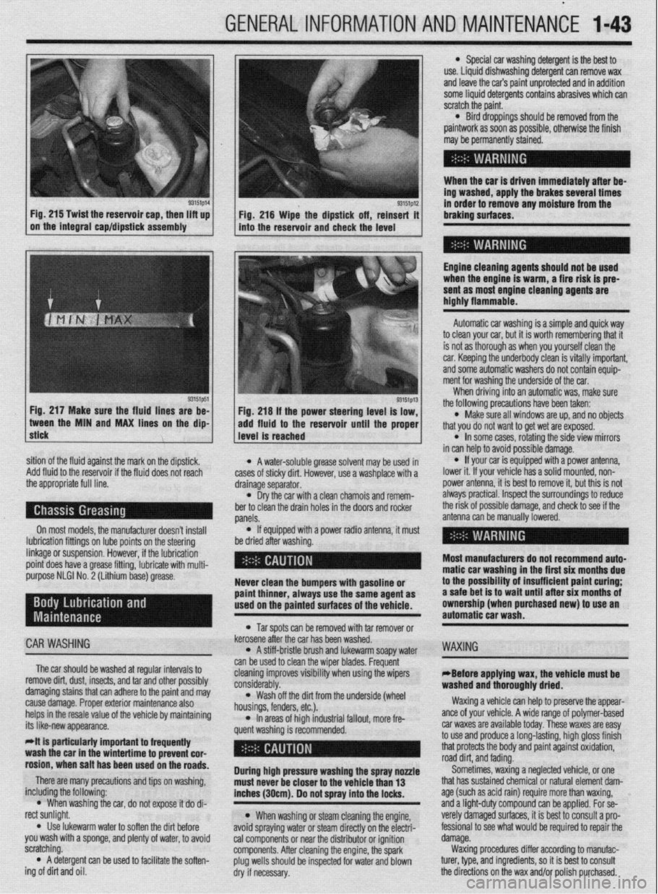
93151p14 93151p12 Fig. 215 Twist the reservoir cap, then lift up
I I
in order to remove any moisture from the
Fig. 216 Wipe the dipstick off, reinsert it braking surfaces.
on the integral cap/dipstick assembly
into the reservoir and check the level
I
Engine cleaning agents should not be used
when the engine is warm, a fire risk is pre-
sent as most engine cleaning agents are
highly flammable.
sition of the fluid against the mark on the dipstick,
Add fluid to the reservoir if the fluid does not reach
the appropriate full line.
On most models, the manufacturer doesn’t install
lubrication fittings on lube points on the steering
linkage or suspension. However, if the lubrication
point does have a grease fitting, lubricate with multi-
purpose NLGI No. 2 (Lithium base) grease.
CAR WASHING
The car should be washed at regular intervals to
remove dirt, dust, insects, and tar and other possibly
damaging stains that can adhere to the paint and may
cause damage. Proper exterior maintenance also
helps in the resale value of the vehicle by maintaining
its like-new appearance.
Mt is particularly important ta frequentiy
wash the car in the wintertime to prevent cor-
rosion, when salt has been used on the roads.
There are many precautions and tips on washing,
including the following:
l When washing the car, do not expose it do di-
rect sunlight.
. Use lukewarm water to soften the dirt before
you wash with a sponge, and plenty of water, to avoid
scratching.
l A detergent can be used to facilitate the soften-
ing of dirt and oil. * A water-soluble grease solvent may be used in
cases of sticky dirt. However, use a washplace with a
drainage separator.
l Dry the car with a clean chamois and remem-
ber to clean the drain holes in the doors and rocker
panels.
l If equipped with a power radio antenna, it must
be dried after washing.
Never clean the bumpers with gasoline or
paint thinner, always use the same agent as
used on the painted surfaces of the vehicle.
l Tar spots can be removed with tar remover or
kerosene after the car has been washed.
l A stiff-bristle brush and lukewarm soapy water
can be used to clean the wiper blades. Frequent
cleaning improves visibility when using the wipers
considerably.
l Wash off the did from the underside (wheel
housings, fenders, etc.).
l In areas of high industrial fallout, more fre-
quent washing is recommended.
During high pressure washing the spray nonle
must never be closer to the vehicle than 13
inches (30cm). Do not spray into the locks.
l When washing or steam cleaning the engine,
avoid spraying water or steam directly on the electri-
cal components or near the distributor or ignition
components. After cleaning the engine, the spark
plug wells should be inspected for water and blown
dry if necessary. Automatic car washing is a simple and quick way
to clean your car, but it is worth remembering that it
is not as thorough as when you yourself clean the
car. Keeping the underbody clean is vitally important,
and some automatic washers do not contain equip-
ment for washing the underside of the car.
When driving into an automatic was, make sure
the following precautions have been taken:
l Make sure all windows are up, and no objects
that you do not want to get wet are exposed.
l In some cases, rotating the side view mirrors
in can help to avoid possible damage.
l If your car is equipped with a power antenna,
lower it. If your vehicle has a solid mounted, non-
power antenna, it is best to remove it, but this is not
always practical. Inspect the surroundings to reduce
the risk of possible damage, and check to see if the
antenna can be manually lowered.
Most manufacturers do not recommend auto-
matic car washing in the first six months due
to the possibility of insufficient paint curing;
a safe bet is to wait until after six months of
ownership (when purchased new) to use an
automatic car wash.
WAXING
eBefore applying wax, the vehicle must be
washed and thoroughly dried.
Waxing a vehicle can help to preserve the appear-
ante of your vehicle. A wide range of polymer-based
car waxes are available today. These waxes are easy
to use and produce a long-lasting, high gloss finish
that protects the body and paint against oxidation,
road dirt, and fading.
Sometimes, waxing a neglected vehicle, or one
that has sustained chemical or natural element dam-
age (such as acid rain) require more than waxing,
and a light-duty compound can be applied. For se-
verely damaged surfaces, it is best to consult a pro-
fessional to see what would be required to repair the
damage.
Waxing procedures differ according to manufac-
turer, type, and ingredients, so it is best to consult
the directions on the wax and/or polish purchased.
Page 43 of 408
1-44 GENERALINFORMATIONAND MAINTENANCE
INTERIOR CLEANING
Upholstery
Fabric can usually be cleaned with soapy water or
a proper detergent. For more difficult spots caused by
oil, ice cream, soda, etc., use a fabric cleaner avail-
able at most parts stores. Be sure when purchasing
the cleaner to read the label to ensure it is safe to use
on your type of fabric. A safe method of testing the
cleaner is to apply a small amount to an area usually
unseen, such as under a seat, or other areas. Wart a
while, perhaps even a day to check the spot for fad-
ing, discoloring, etc., as some cleaners will only
cause these problems after they have dried
Leather upholstery requrres special care, it can be
cleaned with a mild soap and a soft cloth. It is recom-
mended that a special leather cleaner be used to
clean but also treat the leather surfaces in your vehi-
cle. Leather surfaces can age quickly and can crack if
not properly taken care of, so it is vital that the leather
surfaces be maintained.
Floor Mats and Carpet
The floor mats and carpet should be vacuumed or
brushed regularly. They can be cleaned with a mild
soap and water. Special cleaners are available to
clean the carpeted surfaces of your vehicle, but take
care in choosing them, and again it is best to test
them in a usually unseen spot.
Dashboard, Console, Door Panels, Etc.
The dashboard, console, door panels, and other
plastic, vinyl, or wood surfaces can be cleaned using
a mild soap and water. Caution must be taken to keep
water out of electronic accessories and controls to
avoid shorts or ruining the components Again spe-
cial cleaners are available to clean these surfaces, as
with other cleaners care must taken in purchasmg
and using such cleaners.
There are protectants available which can treat the
various surfaces in your car giving them a “shiny new
look”, however some of these protectants can cause
more harm than good in the long run. The shine that
is placed on your dashboard attracts sunlight accel-
erating the aging, fading and possibly even cracking
the surfaces. These protectants also attract more dust
to stick to the surfaces they treat, Increasing the cleaning you must do to maintain the appearance of
your vehicle. Personal discretion is advised here.
On most models covered by this manual, the
wheel bearmgs used are sealed units and do not re-
quire routine maintenance. However on some Galant
and Mirage models, the rear wheel bearing do require
periodic repacking. For removal and installation in-
structions, please refer to Section 7 (for rear bear-
ings) or Section 8 (for front bearings).
REPACKING
*Sodium based grease is not compatible
with lithium based grease. Read the package
labels and be careful not to mix the two
types. If there is any doubt as to the type of
grease used, completely clean the old
grease from the bearing and hub before re-
placing.
Before handling the bearings, there are a few
things that you should remember to do and not to do.
DO the following: l Remove all outside dirt from the housing be-
fore exposing the bearing.
l Treat a used bearing as gently as you would a
new one.
l Work with clean tools in clean surroundings. l Use clean, dry gloves, or at least clean, dry
hands.
l Clean solvents and flushing fluids are a must. l Use clean paper when laying out the bearings
to dry.
l Protect drsassembled bearings from rust and
dirt. Cover them up.
l Use clean, lint-free rags to wipe the bearings. l Keep the bearings in oil-proof paper when they
are to be stored or are not in use.
l Clean the inside of the housing before replac-
ing the bearin
Do NOT do he followino: El, l Do not work in dirty sirroundings. l Do not use dirty, chipped or damaged tools. l Do not work on wooden work benches or use
wooden mallets.
l Do not handle bearings with dirty or moist
hands.
l Do not use gasoline for cleaning. Use a safe
solvent.
l Do not spin dry bearings with compressed air.
They will be damaged.
l Do not use cotton waste or dirty cloths to wipe
bearings.
l Do not scratch or nick bearing surfaces. l Do not allow the bearina to come in contact
” with dirt or rust at any time.
The rear wheel bearinas on some Galant and Mi-
rage models require periodic maintenance. A pre-
mium high melting point grease meeting Grade
Multipurpose Grease NLGI Grade #2 or equivalent
must be used. Long fiber type greases must not be
used. This service is recommended every 30,000
miles (48,000 km).
*For information on Wheel Bearing removal
and installation, refer to Section 7 of this
manual.
1. Remove the wheel bearing.
2. Clean all parts in a non-flammable solvent and
let them air dry.
*Only use lint-free rags to dry the bearings.
Never spin-dry a bearing with compressed
air, as this will damage the rollers.
3. Check for excessive wear and damage. Replace
the bearing as necessary.
*Packina wheel bearinos with arease is
best accomplished by u&g a wheel bearing
packer (available at most automotive parts
stores).
4. If a wheel bearing packer is not available, the
bearings may be packed by hand.
a. Place a “healthy’ glob of grease in the
palm of one hand.
b. Force the edge of the bearing into the
grease so that the grease fills the space between
the rollers and the bearing cage.
c. Keep rotating the bearing while continuing
to push the grease through.
d. Continue until the grease is forced out the
other side of the bearing.
5. Place the packed bearing on a clean surface
and cover it until it is time for installation.
6. Install the wheel bearing.
# See Figures 219 and 220
To prevent the bumper from deforming, these vehi-
cles cannot be towed by a wrecker using sling-type
equipment. If these vehicles require towing, use a
wheel lift or flat bed equipment. It is recommended
that the vehicle be towed from the front If a flat bed is
not available.
Manual transaxle vehicles may be towed from the
rear provided that the transaxle is in Neutral and the
driveline has not been damaged. The steering wheel
must be clamped in the straight-ahead positron with a
steering wheel clamping device designed for towing
service use.
Do not use the steering column lock to secure
the front wheel uosition for towina.
Automatic transaxle vehicles may be towed on the
front wheels at speeds not to exceed 30 mph (50
km/h) for a distance not to exceed 18 miles (30 km).
If these limits can not be met, then the front wheels
must be placed on a tow dolly.
# See Figure 221
All Wheel Drive (AWD) vehicles should only be
towed with all 4 wheels on the ground or lifted from
the road surface. This means that the vehicle is to be
towed either with flatbed equipment, with all wheels
on dollies or flat towed. Damage to the viscous cou-
pling may result if the vehicle is towed with only 2
wheels on the ground.
p See Figure 222
Whenever a vehicle is jump started, precautions
must be followed In order to prevent the possibility of
Page 46 of 408
GENERAL INFORMATION AND MAINTENANCE 1-47
ramps are also a handy and safe way to both raise l When the drive wheels are to remain on the
and support the vehicle. Be careful though, some ground, leave the vehicle in gear to help prevent it
ramps may be too steep to drive your vehicle onto
The following safety points cannot be overempha- from rolling.
without scraping the front bottom panels. Never sup-
sized:
l Always use jackstands to support the vehicle
port the vehicle on any suspension member (unless l Always block the opposite wheel or wheels to when you are working underneath. Place the stands
specifically instructed to do so by a repair manual) or
keep the vehicle from rolling off the jack. beneath the vehrcle’s jacking brackets Before climb-
by an underbody panel.
l When raising the front of the vehicle, firmly ap- ing underneath, rock the vehicle a bit to make sure it
ply the parking brake. is firmly supported.
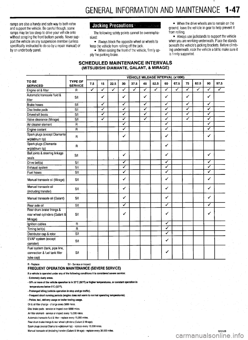
SCHEDULED MAINTENANCE INTERVALS (MITSUBISHI DIAMANTE, GALANT, & MIRAGE)
VEHICLE MILEAGE INTERVAL (x1000)
7.5 15
22.5 30 37.5 45 52.5 60 67.5 75 62.5 90 97.5
J J
J 4 J J 4 4 4 J J
J 4
4
J J J J 4 TO BE
Ball loints &steering linkage
S/I J J J
seals
Dnve belt(s) S/I 4 4 J
Fvha,,rt cvctom $/I
J J J LmI,..“w. “,YL”,‘. Fuel hoses
+
Manual transaxle oil (Galant)
connectlon & fuel tank filler
R. Replace S/I - Sefwce or Inspect FREQUENT OPERATION MAINTENANCE (SEVERE SERVICE) II a vehicle is operated under any of the following conditions it is considered severe service:
- Extremely dusty areas.
- 50% or more of the vehicle operation is in 32% (WF) or higher temperatures, or constant opsralion in
temperatures below 0% (32°F).
- Prolonged idling (vehicle operation in stop and go traffic).
_ Frequent short running periods (engine does not warm to normal operating temfwatures).
- Police, taxi, delivery usage or trailer towing usage.
0118 011 filter change-change every 3CQO miles.
Disc brake pads - sewce or Inspect ever 6COO miles
AN hlter element _ setwe or inspect every 15,000 miles.
Automatic transaxle lluld 8 filter . replace every 15,COO m&s.
Rear drum brake Ikmngs & rear wheel cylinders (Galant & Mirage)
Spark plugs (except Dlamante wlplabnum tip) - replace every 15,COO miles.
Manual transaxle 011 (mcludlng transfer (Galant & Mirage). replace every 30,000 miles.
Page 79 of 408
l
3-18 ENGINEANDENGINEOVERHAUL
bolt and gaskets that connect the oil feed line to the
turbo center section and the water cooling lines. The
water line under the turbo has a threaded connection.
8. Remove the exhaust pipe nuts and gasket and
lift off the exhaust manifold. Discard the gasket,
9. Remove the 2 through bolts and 2 nuts that 16. If removed, install the power steering pump
and bracket.
17. Install the heat shields, air outlet hose, waste-
gate hose and air intake bellows.
18. Install the oil dipstick tube and dipstick. In-
stall the oxyqen sensor. cient quantities. Always drain coolant into a
sealable container. Coolant should be reused
unless it is contaminated or is several years
old.
3. Disconnect the overflow tube. Some vehicles
hold the exhaust manifold to the turbocharger,
10. Remove the 2 capscrews from the oil return
line (under the turbo). Discard the gasket. Separate
the turbo from the exhaust manifold. The 2 water
pipes and oil feed line can still be attached. 19. In&h the radiator assembly.
20. Fill the engine with oil, fill the cooling system
and reconnect the negative battery cable.
11. Visually check the turbine wheel (hot side)
and compressor wheel (cold side) for cracking or
other damage. Check whether the turbine wheel and
the compressor wheel can be easily turned by hand.
Check for oil leakaae. Check whether or not the Operating the engine without the proper
amount and type of engine oil will result in
severe engine damage.
wastegate valve remains open. If any problem is .
found, replace the part. Inspect oil passages for re- #I , I
striction or deposits and clean as required,
12. The wasteaate can be checked with a ores-
REMOVAL & INSTALLATION sure tester. Apply approximately 9 psi to the&h&or
and make sure the rod moves. Do not apply more
than 10.3 psi or the diaphragm in the wastegate may
be damaged. Vacuum applied to the wastegate actua-
tor should be maintained, replace if leaks vacuum,
Do not attempt to adjust the wastegate valve. $ See Figures 77 thru 91
I. Disconnect the negative battery cable.
2. Drain the cooling system when safe.
To
install: 13. Prime the oil return line with clean engine oil.
Replace all locking nuts. Before installing the
threaded connection for the water inlet pipe, apply
light oil to the inner surface of the pipe flange. As-
semble the turbocharger and exhaust manifold.
14. Install the exhaust manifold using a new gas-
ket.
15. Connect the water cooling lines, oil feed line
and engine hanger. Never open, service or drain the radiator or
cooling system when hot: serious burns can
occur from the steam and hot coolant. Also,
when draining engine coolant, keep in mind
that cats and dogs are attracted to ethylene
glyeol antifreeze and could drink any that is
left in an uncovered container or in puddles
on the ground. This will prove fatal in suffi-
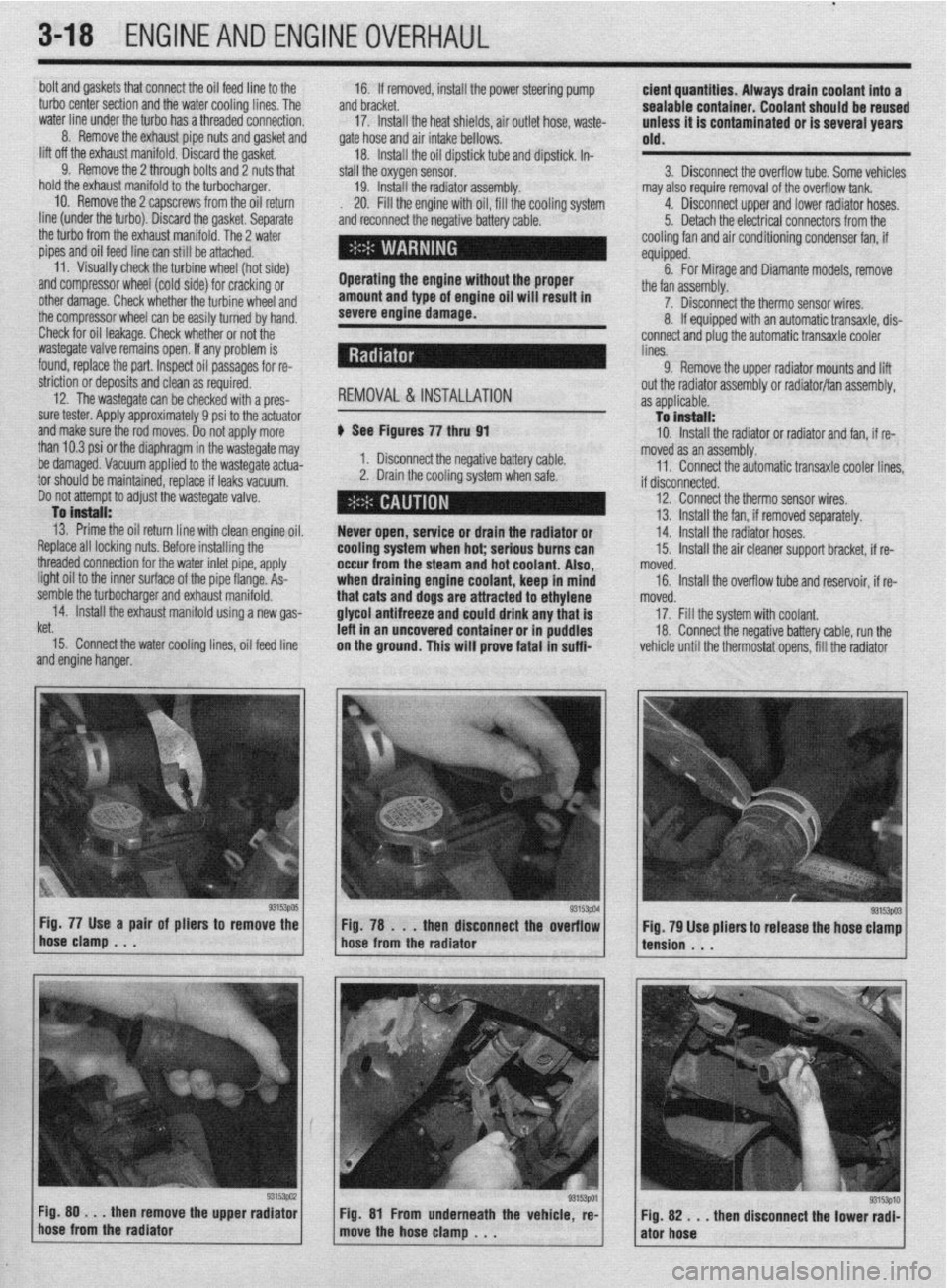
Fig. 77 Use a pair of pliers to remove the
Fig. 78 . . .
then disconnect the overflow
hose clamp . . .
hose from the radiator may also require removal of the overflow tank.
4. Disconnect upper and lower radiator hoses.
5. Detach the electrical connectors from the
cooling fan and air conditioning condenser fan, if
equipped.
6. For Mirage and Diamante models, remove
the fan assembly.
7. Disconnect the therm0 sensor wires,
8. If equipped with an automatic transaxle, dis-
connect and plug the automatic transaxle cooler
lines.
9. Remove the upper radiator mounts and lift
out the radiator assembly or radiator/fan assembly,
as applicable.
To install:
10. Install the radiator or radiator and fan, if re-
moved as an assembly.
11. Connect the automatic transaxle cooler lines
if disconnected.
12. Connect the therm0 sensor wires,
13. Install the fan, if removed separately.
14. Install the radiator hoses.
15. Install the air cleaner support bracket, if re-
noved.
16. Install the overflow tube and reservoir, if re-
noved.
17. Fill the system with coolant.
18. Connect the negative battery cable, run the
vehicle until the thermostat opens, fill the radiator
93153003 Fig. 79 Use pliers to release the hose clamp
tension . . .
Fig. 80 . . .
then remove the upper radiator
hose from the radiator Fig. 81 From underneath the vehicle, re-
move the hose clamp , . . ”
then disconnect the lower radi- Fig. 82 . . .
ator hose
Page 120 of 408
ENGINEAND ENGINEOVERHAUL 3-59
Most of the cleaning process can be carried out
with common hand tools and readily available sol-
vents or solutions. Carbon deposits can be chipped
away using a hammer and a hard wooden chisel. Old
gasket material and varnish or sludge can usually be
removed using a scraper and/or cleaning solvent. Ex-
tremely stubborn deposits may require the use of a
power drill wrth a wire brush. If using a wire brush,
use extreme care around any critical machined sur-
faces (such as the gasket surfaces, bearing saddles,
cylinder bores, etc.). USE OF A WIRE BRUSH IS NOT
RECOMMENDED ON ANY ALUMINUM COMPO-
NENTS Always follow any safety recommendations
given by the manufacturer of the tool and/or solvent.
You should always wear eye protection during any
cleaning process involvrng scraping, chipping or
spraying of solvents.
An alternative to the mess and hassle of cleaning
the parts yourself is to drop them off at a local garage
or machine shop. They will, more than likely, have
the necessary equrpment to properly clean all of the
parts for a nominal fee.
Always wear eye protection during any clean-
ing process involving scraping, chipping or
spraying of solvents.
Remove any oil galley plugs, freeze plugs and/or
pressed-in bearings and carefully wash and degrease
all of the engine components including the fasteners
and bolts. Small parts such as the valves, springs,
etc., should be placed in a metal basket and allowed
to soak. Use pipe cleaner type brushes, and clean all
passageways in the components. Use a ring ex-
pander and remove the rings from the pistons. Clean
the piston ring grooves with a special tool or a piece
of broken ring Scrape the carbon off of the top of the
piston. You should never use a wire brush on the
pistons. After preparing all of the piston assemblies
in this manner, wash and degrease them again.
Use extreme care when cleaning around the
cylinder head valve seats. A mistake or slip
may cost you a new seat.
When cleaning the cylinder head, remove carbon
from the combustron chamber with the valves in-
stalled. This will avoid damaging the valve seats.
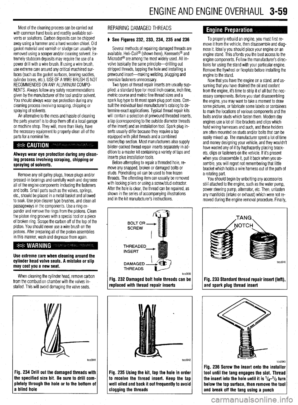
:ig. 234 Drill out the damaged threads with
he specified size bit. Be sure to drill corn.
rletely through the hole or to the bottom oi
I blind hole REPAIRING DAMAGEDTHREADS
# See Figures 232, 233, 234, 235 and 236
Several methods of repairing damaged threads are
available Heli-Coil@ (shown here), Keenserts@ and
Microdop are among the most widely used. All in-
volve basically the same principle-drilling out
stripped threads, tapping the hole and installing a
prewound insert-making welding, plugging and
oversize fasteners unnecessary.
Two types of thread repair inserts are usually sup-
plied: a standard type for most inch coarse, rnch fine,
metric course and metrrc fine thread sizes and a
spark lug type to fit most spark plug port sizes. Con-
sult the individual tool manufacturers catalog to de-
termine exact applications. Typical thread repair kits
will contain a selection of prewound threaded inserts,
a tap (corresponding to the outside diameter threads
of the insert) and an installation tool. Spark plug in-
serts usually differ because they require a tap
equipped wrth pilot threads and a combined
reamer/tap section. Most manufacturers also supply
blister-packed thread repair Inserts separately in ad-
dition to a master kit containing a variety of taps and
inserts plus installation tools
Before attempting to repair a threaded hole, re-
move any snapped, broken or damaged bolts or
studs. Penetrating oil can be used to free frozen
threads. The offending item can usually be removed
with locking pliers or using a screw/stud extractor.
After the hole is clear, the thread can be reparred, as
shown in the series of accompanying illustrations
and in the krt manufacturers instructions.
THREADED
lCCS3039
replaced with thread repair inserts
:ig. 235 Using the kit, tap the hole in order
o receive the thread insert. Keep the tap
veil oiled and back it out frequently to avoid
:logging the threads
To properly rebuild an engine, you must first re-
move it from the vehicle, then disassemble and diag-
nose it. Ideally you should place your engine on an
engine stand. This affords you the best access to the
engine components. Follow the manufacturers direc-
tions for using the stand with your particular engine.
Remove the flywheel or flexplate before installing the
engine to the stand.
Now that you have the engine on a stand, and as-
suming that you have drained the oil and coolant
from the engine, it’s time to strip it of all but the nec-
essary components. Before you start disassembling
the engine, you may want to take a moment to draw
some pictures, or fabricate some labels or containers
to mark the locations of various components and the
bolts and/or studs which fasten them. Modern day
engines use a lot of little brackets and clips which
hold wiring harnesses and such, and these holders
are often mounted on studs and/or bolts that can be
easily mixed up. The manufacturer spent a lot of time
and money designing your vehicle, and they wouldn’t
have wasted any of it by haphazardly placing brack-
ets, clips or fasteners on the vehicle. If it’s present
when you disassemble it, put it back when you as-
semble, you will regret not remembering that little
bracket which holds a wire harness out of the path of
a rotating part.
You should begin by unbolting any accessories
still attached to the engine, such as the water pump,
power steering pump, alternator, etc. Then, unfasten
any manifolds (intake or exhaust) which were not re-
moved during the engine removal procedure. Finally,
Fig. 233 Standard thread repair insert (left),
and spark plug thread insert
im3043 Fig. 236 Screw the insert onto the installer
1001 until the tang engages the slot. Thread
‘he insert into the hole until it is l/4-l/~ turn
lelow the top surface, then remove the tool
and break off the tano usina a uunch
Page 197 of 408
5-10 FUELSYSTEM
1. _
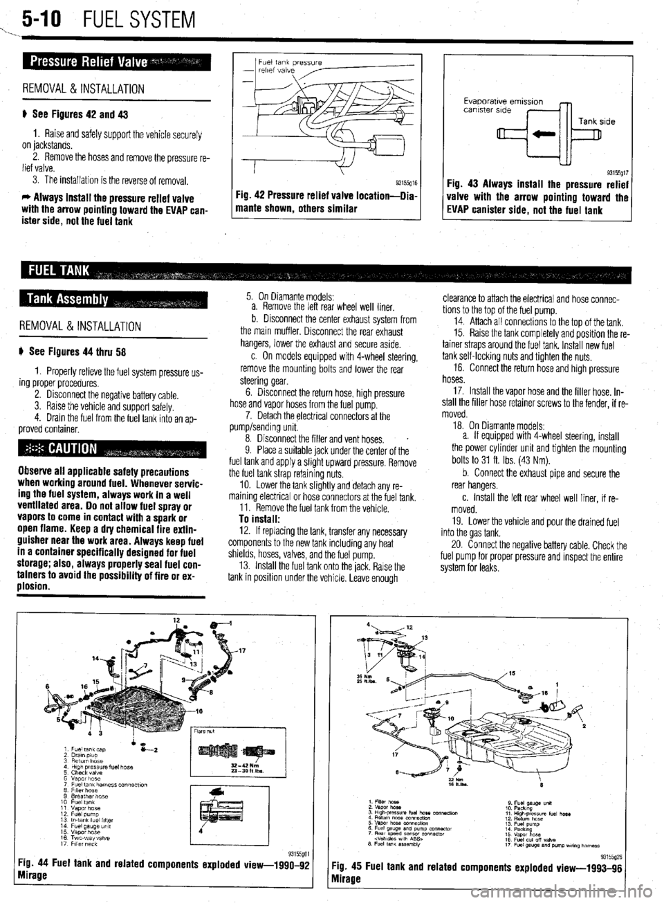
Fuel tank pressure
-
relef vdive
REMOVAL &INSTALLATION
p See Figures 42 and 43
1. Raise and safely support the vehicle securely
on jackstands.
2. Remove the hoses and remove the pressure re-
lief valve.
3. The installation is the reverse of removal.
c, Always install the pressure relief valve
with the arrow pointing toward the EVAP can-
ister side, not the fuel tank 1 mame shown, others similar g3155g” Fig 42 Pressure relief valve location-llia
I I
Evaporatwe emlsslon
canister side
Tank side
+k
93155gt7 Fig. 43 Always install the pressure relief
valve with the arrow pointing toward the
EVAP canister side, not the fuel tank
REMOVAL&INSTALLATION
p See Figures 44 thru 58
1. Properly relieve the fuel system pressure us-
ing proper procedures.
2. Disconnect the negative battery cable.
3. Raise the vehicle and support safelv.
4. Drain the fuel from the fuel tank into an
ap- proved container.
Observe all applicable safety precautions
when working around fuel. Whenever servic-
ing the fuel system, always work in a well
ventilated area. Do not allow fuel spray or
vapors to come in contact with a spark or
open flame. Keep a dry chemical fire extin-
guisher near the work area. Always keep fuel
in a container specifically designed for fuel
storage; also, always properly seal fuel con-
tainers to avoid the possibility of fire or ex-
plosion.
5. On Diamante models:
a. Remove the left rear wheel well liner.
b Disconnect the center exhaust system from
the main muffler. Disconnect the rear exhaust
hangers, lower the exhaust and secure aside.
c. On models equipped with 4-wheel steering,
remove the mounting bolts and lower the rear
steering gear.
6. Disconnect the return hose, high pressure
hose and vapor hoses from the fuel pump.
7. Detach the electrical connectors at the
pump/sending unit.
8. Disconnect the filler and vent hoses.
s
9. Place a suitable jack under the center of the
fuel tank and apply a slight upward pressure. Remove
the fuel tank strap retaining nuts.
10. Lower the tank slightly and detach any re-
maining electrical or hose connectors at the fuel tank.
11. Remove the fuel tank from the vehicle.
To install: 12. If replacing the tank, transfer any necessary
components to the new tank including any heat
shields, hoses, valves, and the fuel pump.
13. Install the fuel tank onto the jack. Rarse the
tank in position under the vehicle. Leave enough
Tg. 44 Fuel tank and related components exploded view-1990-92
mirage
clearance to attach the electrical and hose connec-
tions to the top of the fuel pump.
14. Attach all connectrons to the top of the tank.
15. Raise the tank completely and position the re-
tainer straps around the fuel tank. Install new fuel
tank self-locking nuts and tighten the nuts.
16. Connect the return hose and high pressure
hoses.
17. Install the vapor hose and the filler hose. In-
stall the filler hose retainer screws to the fender, if re-
moved.
18. On Diamante models:
a. If equipped with 4-wheel steering, install
the power cylinder unit and tighten the mounting
bolts to 31 ft. Ibs. (43 Nm).
b. Connect the exhaust pipe and secure the
rear hangers.
c. Install the left rear wheel well liner, if re-
moved.
19. Lower the vehicle and pour the drained fuel
into the gas tank.
20. Connect the negative battery cable. Check the
fuel pump for proper pressure and inspect the entire
system for leaks.
:ig. 45
vlirage Fuel tank and related 93155(12E components exploded view-1993-96
Page 213 of 408
640 CHASSIS ELECTRICAL
careful not to allow anything to come in contact with
the air bag unit.
16. Remove the glove box lamp assembly.
17. Remove the remaining instrument panel
mounting screws and remove the instrument panel
from the vehicle.
18. Remove the left side foot shower ductwork,
lap cooler duct and center duct.
19. Remove the front and center reinforcements
and center stay assembly.
20. Remove the air distribution duct assembly.
21. Detach all connectors from heater-box-
mounted items.
22. Remove the heater box mounting screws and
nut, then remove the unit from the vehicle.
23. Disassemble on a workbench. Remove the
heater core from the heater case.
To install:
24. Thoroughly clean and dry the inside of the
case and install the heater core and all related parts.
25. Install the heater unit to the vehicle and install
the mounting screws and nut. Be sure the evaporator
case and heater case are fitted together properly. At-
tach all connectors to heater-box-mounted items.
26. Install the air distribution duct assembly. In-
stall the front and center reinforcements and center
stay assembly.
27. Install the center duct, lap cooler duct and left
side foot shower duct.
28. Install the instrument panel and mounting
screws.
29. Install the glove box lamp assembly.
30. Secure the steering column and attach all
steering column connectors.
31. Install the speedometer cable adapter to the
instrument panel.
32. Install the instrument cluster and the instru-
ment cluster bezel.
33. Install the speakers to the top of the instru-
ment panel.
34. Install the cup holder.
35. Install the climate control system control
head.
36. Install the stereo entertainment system and
bezel.
37. Install the screw below the glove box assem-
bly, and the entire glove box unit.
38. Install the steering column covers.
39. Install the knee protector support bracket, the
protector and the decorative plugs.
40. Install the console and the ashtray. 41. Install the right side foot shower duct.
42. Install the passenger side undercover.
43. Connect the heater hoses to the core tubes.
44. Fill the cooling system.
45. Connect the negative battery cable and check
the entire climate control system for proper operation
and leaks.
Galant
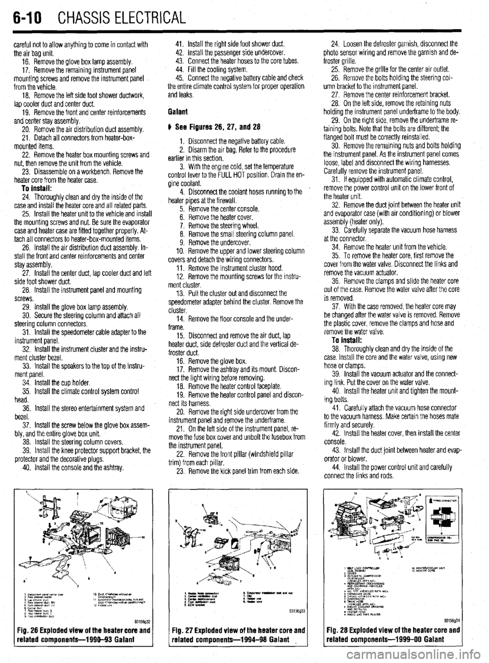
# See Figures 26, 27, and 28
1. Disconnect the negative battery cable.
2. Disarm the air bag. Refer to the procedure
earlier in this section.
3. With the engine cold, set the temperature
control lever to the FULL HOT position. Drain the en-
gine coolant.
4. Disconnect the coolant hoses running to the
heater pipes at the firewall.
5. Remove the center console.
6. Remove the heater cover.
7. Remove the steering wheel.
8. Remove the small steering column panel.
9. Remove the undercover.
10. Remove the upper and lower steering column
covers and detach the wiring connectors.
11. Remove the instrument cluster hood.
12. Remove the mounting screws for the instru-
ment cluster.
13. Pull the cluster out and disconnect the
speedometer adapter behind the cluster. Remove the
cluster.
14. Remove the floor console and the under-
frame.
15. Disconnect and remove the air duct, lap
heater duct, side defroster duct and the vertical de-
froster duct.
16. Remove the glove box.
17. Remove the ashtray and its mount. Discon-
nect the light wiring before removing.
18. Remove the heater control faceplate.
19. Remove the heater control panel and discon-
nect its harness.
20. Remove the right side undercover from the
instrument panel and remove the underframe.
21. On the left side of the instrument panel, re-
move the fuse box cover and unbolt the fusebox from
the instrument panel.
22. Remove the front pillar (windshield pillar
trim) from each pillar.
23. Remove the kick panel trim from each side.
Fig. 26 Exploded view of the heater core and
related components-1990-93 Galant
:IQ. 27 Exploded view of the heater core and
-elated components-1994-98 Galant 24. Loosen the defroster garnish, disconnect the
photo sensor wiring and remove the garnish and de-
froster grille.
25. Remove the grille for the center air outlet.
26. Remove the bolts holding the steering col-
umn bracket to the instrument panel.
27, Remove the center reinforcement bracket.
28. On the left side, remove the retaining nuts
holding the instrument panel underframe to the body.
29. On the right side, remove the underframe re-
taining bolts. Note that the bolts are different; the
flanged bolt must be correctly reinstalled.
30. Remove the remaining nuts and bolts holding
the instrument panel. As the instrument panel comes
loose, label and disconnect the wiring harnesses.
Carefully remove the instrument panel.
31. If equipped with automatic climate control,
remove the power control unit on the lower front of
the heater unit.
32. Remove the duct joint between the heater unit
and evaporator case (with air conditioning) or blower
assembly (heater only).
33. Carefully separate the vacuum hose harness
at the connector.
34. Remove the heater unit from the vehicle.
35. To remove the heater core, first remove the
cover from the water valve. Disconnect the links and
remove the vacuum actuator.
36. Remove the clamps and slide the heater core
out of the case. Remove the water valve after the core
is removed.
37. With the case removed, the heater core may
be changed after the water valve is removed. Remove
the plastic cover, remove the clamps and hose and
remove the water valve.
To install:
38. Thoroughly clean and dry the inside of the
case. Install the core and the water valve, using new
hose or clamps.
39. Install the vacuum actuator and the connect-
ing link. Put the cover on the water valve.
40. Install the heater unit and tighten the mount-
ing bolts.
41. Carefully attach the vacuum hose connector
to the vacuum harness. Make certain the hoses mate
firmly and securely.
42. Install the heater cover, then install the center
console.
43. Install the duct joint between heater and evap-
orator or blower.
44. Install the power control unit and carefully
connect the links and rods.
Fig. 28 Exploded view of the heater core and
related components-1999-00 Galant