1900 MITSUBISHI DIAMANTE ad blue
[x] Cancel search: ad bluePage 49 of 408
.~ P.X I_ - “, .- I .-., IS ” .~.I .r
2-2 ENGINE ELECTRICAL
nn
ity and trouble: shooting electrical circuits,
please refer to Section 6 of this manual.
I
The ignition system on the 1.5L, 1993-96 1.8L,
2.OL SOHC, 1994-98 2.4L SOHC, 3.OL SOHC, and
3.5L engines uses a pointless type distributor, whose
advance mechanism is controlled by the Engine Con-
trol Unit (ECU). On the 1.5L, 1.8L, 2.4L and 3.5L en-
gines, the distributor houses a built in ignition coil
and ignition power transistor. The 2.8L SOHC and
3.OL SOHC engines utilize a separate coil and tran-
sister assemblv.
When the ignition switch is turned ON, battery
voltage is applied to the ignition coil primary winding.
As the shaft of the distributor rotates, signals are
transmitted from the oowertrain control module to the
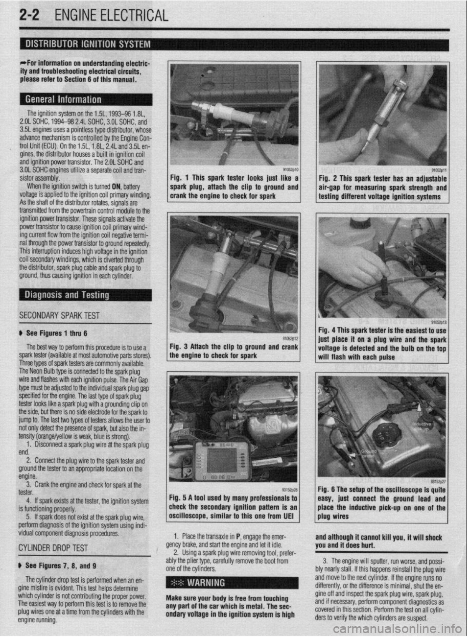
9105zp11 Fig. 1 This spark tester looks iust like a
Fiu. 2 This spark tester has an adjustable
spark plug, attach the clip to ground and air-gap for measuring spark strength and
crank the engine to check for spark testing different voltage ignition systems
.
ignition power trar rsistor. These signals activate the
power transistor to cause ignition coil primary wind-
ing current flow from the ignition coil negative termi-
nal through the power transistor to ground repeatedly.
This interruption induces high voltage in the ignition
coil secondarv windinas, which is diverted throuah
the distributor, spark plug cable and spark plug 6
ground, thus causing ignition in each cylinder.
I
SECONDARYSPARKTEST l;h.4-
! ,L ".~
'$ >,%
If See Figures 1 thru 6
91rJszp12 Fig. 4 This spark tester is the easiest to use
iust alace it on a plug wire and the spark
The best way to perform this procedure is to use a Fig. 3 Attach the clip to ground and crank
spark tester (available at most automotive parts stores). the engine to check for spark
I I voltage is detected and the bulb on the tof
-. will flash with each pulse
I nree types ot spark testers are commonly available.
The Neon Bulb type is connected to the spark plug
wire and flashes with each ignition pulse. The Air Gap
type must be adjusted to the individual spark plug gap
specified for the engine. The last type of spark plug
tester looks like a spark plug with a grounding clip on
the side, but there is no side electrode for the spark to
jump to. The last two types of testers allows the user to
not only detect the presence of spark, but also the in-
tensity (orange/yellow is weak, blue is strong).
1. Disconnect a spark plug wire at the spark plug
end.
2. Connect the plug wire to the spark tester and
ground the tester to an appropriate location on the
engine.
3. Crank the engine and check for spark at the
tester.
4. If spark exists at the tester, the ignition system
is functioning properly.
5. If spark does not exist at the spark plug wire,
perform diagnosis of the ignition system using indi-
vidual component diagnosis procedures,
CYLINDER DROPTEST
p See Figures 7, 8, and 9
The cylinder drop test is performed when an en-
gine misfire is evident. This test helps determine
which cylinder is not contributing the proper power.
The easiest way to perform this test is to remove the
plug wires one at a time from the cylinders with the
engine running. 1. Place the transaxle in P, engage the emer-
gency brake, and start the engine and let it idle.
2. Using a spark plug wire removing tool, prefer-
ably the plier type, carefully remove the boot from
one of the cylinders.
i ’
Make sure your body is free from touching
any part of the car which is metal. The sec-
ondary voltage in the ignition system is high and although it cannot kill you, it will shock
you and it does hurt.
3. The engine will sputter, run worse, and possi-
bly nearly stall. If this happens reinstall the plug wire
and move to the next cylinder. If the engine runs no
differently, or the difference is minimal, shut the en-
gine off and inspect the spark plug wire, spark plug,
and if necessary, perform component diagnostics as
covered in this section. Perform the test on all cylin-
ders to verify the which cylinders are suspect.
Page 118 of 408
ENGINEANDENGINEOVERHAUL 3-57
Anything that generates heat and/or friction WIII
eventually burn or wear out (for example, a light bulb
generates heat, therefore its life span is limited). With
this in mind, a running engine generates tremendous
amounts of both; friction is encountered by the mov-
ing and rotating parts inside the engine and heat is
created by friction and combustion of the fuel How-
ever, the engine has systems designed to help reduce
the effects of heat and friction and provide added
longevrty. The oiling system reduces the amount of
friction encountered by the moving parts inside the
engine, while the cooling system reduces heat cre-
ated by friction and combustion If either system is
not maintained, a break-down will be inevitable.
Therefore, you can see how regular maintenance can
affect the service life of your vehicle, If you do not
drain, flush and refill your cooling system at the
proper intervals, deposits WIII begin to accumulate in
the radiator, thereby reducing the amount of heat it
can extract from the coolant The same applies to
your oil and filter; If it is not changed often enough it
becomes laden with contaminates and is unable to
properly lubricate the engine. This increases friction
and wear.
There are a number of methods for evaluating the
condition of your engine. A compression test can re-
veal the condition of your pistons, piston rings,
cylinder bores, head gasket(s), valves and valve
seats. An oil pressure test can warn you of possible
engine bearing, or oil pump failures. Excessrve oil
consumption, evidence of oil in the engine air intake
area and/or bluish smoke from the tailpipe may indi-
cate worn piston rings, worn valve guides and/or
valve seals. As a general rule, an engine that uses no
more than one quart of oil every 1000 miles is in
good condition. Engines that use one quart of oil or
more in less than 1000 miles should first be checked
for oil leaks. If any oil leaks are present, have them
fixed before determining how much oil is consumed
by the engine, especrally if blue smoke is not visible
at the tailpipe
COMPRESSION TEST
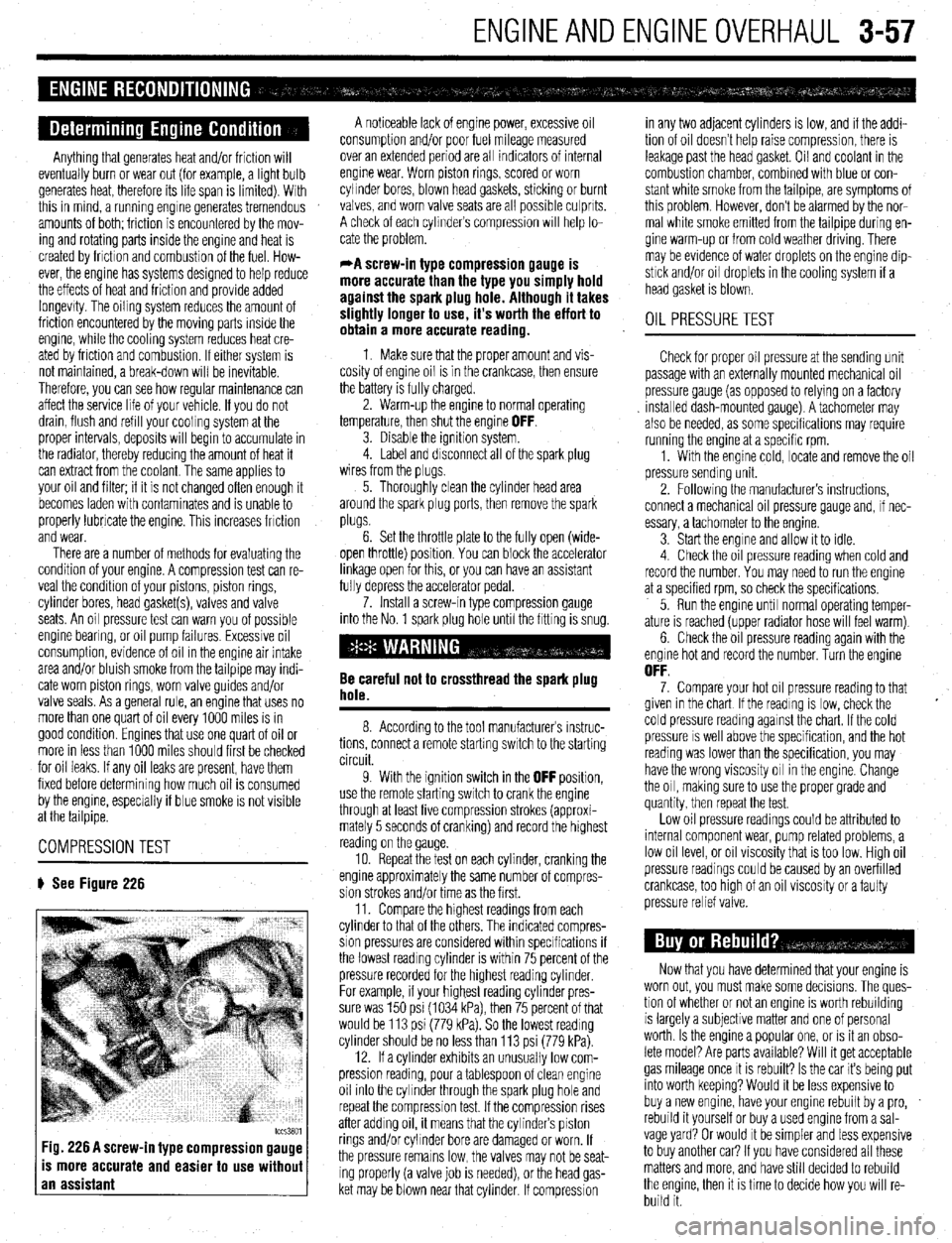
# See Figure 226
tccs3801 Fig. 226 A screw-in type compression gauge
is more accurate and easier to use without
an assistant
A noticeable lack of engine power, excessive oil
consumption and/or poor fuel mileage measured
over an extended period are all indicators of internal
engine wear. Worn piston rings, scored or worn
cylinder bores, blown head gaskets, sticking or burnt
valves, and worn valve seats are all possible culprits.
A check of each cylinders compression WIII help lo-
cate the problem.
*A screw-in type compression gauge is
more accurate than the type you simply hold
against the spark plug hole. Although it takes
slightly longer to use, it’s worth the effort to
obtain a more accurate reading.
1 Make sure that the proper amount and vis-
cosity of engine oil is in the crankcase, then ensure
the battery is fully charged.
2. Warm-up the engine to normal operating
temperature, then shut the engine
OFF. 3. Disable the ignition system.
4. Label and disconnect all of the spark plug
wires from the plugs,
5. Thoroughly clean the cylinder head area
around the spark plug ports, then remove the spark
plugs.
6. Set the throttle plate to the fully open (wide-
open throttle) position You can block the accelerator
linkage open for this, or you can have an assistant
fully depress the accelerator pedal.
7. Install a screw-in type compression gauge
into the No. 1 spark plug hole until the fitting is snug.
Be careful not to crossthread the spark plug
hole.
8. According to the tool manufacturers instruc-
tions, connect a remote starting switch to the starting
circuit.
9. With the ignition switch in the
OFF position,
use the remote starting switch to crank the engine
through at least five compression strokes (approxi-
mately 5 seconds of cranking) and record the highest
reading on the gauge
10. Repeat the test on each cylinder, cranking the
engine approximately the same number of compres-
sion strokes and/or time as the first.
11. Compare the hrghest readings from each
cylinder to that of the others. The indicated compres-
sion pressures are considered within specifications if
the lowest reading cylinder is within 75 percent of the
pressure recorded for the highest reading cylinder
For example, if your highest reading cylinder pres-
sure was 150 psi (1034 kPa), then 75 percent of that
would be 113 psi (779 kPa). So the lowest reading
cylinder should be no less than 113 psi (779 kPa).
12. If a cylinder exhibits an unusually low com-
pression reading, pour a tablespoon of clean engine
oil into the cylinder through the spark plug hole and
repeat the compression test. If the compression rises
after adding oil, it means that the cylinder’s piston
rings and/or cylinder bore are damaged or worn, If
the pressure remains low, the valves may not be seat-
ing properly (a valve job is needed), or the head gas-
ket may be blown near that cylinder. If compression in any two adjacent cylinders is low, and if the addi-
tion of oil doesn’t help raise compression, there is
leakage past the head gasket. Oil and coolant in the
combustion chamber, combined with blue or con-
stant white smoke from the tailpipe, are symptoms of
this problem. However, don’t be alarmed by the nor-
mal white smoke emitted from the tailpipe during en-
gine warm-up or from cold weather driving. There
may be evidence of water droplets on the engine dip-
stick and/or oil droplets in the cooling system if a
head gasket is blown.
OIL PRESSURETEST
Check for proper oil pressure at the sending unit
passage with an externally mounted mechanical oil
pressure gauge (as opposed to relying on a factory
Installed dash-mounted gauge). A tachometer may
also be needed, as some specifications may require
running the engine at a specific rpm.
1. With the engine cold, locate and remove the oil
pressure sending unit.
2. Followrng the manufacturers instructions,
connect a mechanical oil pressure gauge and, if nec-
essary, a tachometer to the engine.
3 Start the engine and allow it to idle.
4 Check the oil pressure reading when cold and
record the number. You may need to run the engine
at a specified rpm, so check the specifications,
5. Run the engine until normal operating temper-
ature is reached (upper radiator hose will feel warm)
6. Check the oil pressure reading again with the
engine hot and record the number. Turn the engine
OFF. 7. Compare your hot oil pressure reading to that
given in the chart If the reading is low, check the
cold pressure reading against the chart. If the cold
pressure IS well above the specification, and the hot
reading was lower than the specification, you may
have the wrong viscosity oil in the engine. Change
the oil, making sure to use the proper grade and
quantity, then repeat the test.
Low oil pressure readings could be attributed to
internal component wear, pump related problems, a
low oil level, or oil viscosity that is too low. High oil
pressure readings could be caused by an overfilled
crankcase, too htgh of an oil viscosity or a faulty
pressure relief valve.
Now that you have determined that your engine is
worn out, you must make some decisions. The ques-
tion of whether or not an engine IS worth rebuilding
is largely a subjective matter and one of personal
worth. Is the engine a popular one, or IS it an obso-
lete model? Are parts available? Will it get acceptable
gas mileage once It is rebuilt? Is the car its being put
into worth keeping? Would it be less expensive to
buy a new engine, have your engine rebuilt by a pro,
rebuild it yourself or buy a used engine from a sal-
vage yard? Or would It be simpler and less expensive
to buy another car? If you have considered all these
matters and more, and have still decided to rebuild
the engine, then it is time to decide how you will re-
build it.
Page 128 of 408
ENGINEANDENGINEOVERHAUL 3-67
CONNECTING ROD
You should have the connecting rod checked for
StraiQhtness at a machine shop. If the connecting rod
is bent, it will unevenly wear the bearing and piston,
as well as place greater stress on these components.
Any bent or twisted connecting rods must be re-
placed. If the rods are straight and the wrist pin clear-
ance is within specifications, then only the bearing
end of the rod need be checked. Place the connecting
rod into a vice, with the bearing inserts in place, in-
stall the cap to the rod and torque the fasteners to
specifications. Use a telescoping gauge and carefully
measure the inside diameter of the bearings. Com-
pare this reading to the rods original crankshaft jour-
nal diameter measurement. The difference is the oil
clearance. If the oil clearance is not within specifica-
tions, install new bearings in the rod and take another
.
specifica- L
need to
shop as the pistons must be installed in the con measurement. it the Clearance is still out of :
tions, and the crankshaft is not, the rod will
be reconditioned by a machine shop.
*You can also use Plastigage’
@to check the
bearing clearances. The assen- . ...= - _______
Mm sectinn has complete instructions on its use.
Camshaft
Inspect the camshaft and lifters/followers as de
scribed earlier in this section.
Bearings
All of the enaine bearinos should be visuallv in-
~~~ I~ .- - -- ..-_-..,
spected for we; and/or damage. The bearing should
look evenly worn all around with no deep scores or
pits. If the bearing is severely worn, scored, pitted or
heat blued, then the bearing, and the components
that use it, should be brought to a machine shop for
block. ,ect
relationshipto the rod or engine damage can occur,
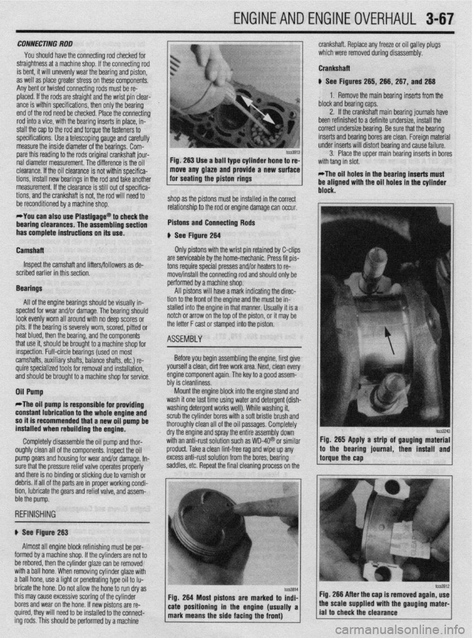
Pistons and Connecting Rods
I
b See Fiaute 264 --- --*------
Only pistons with the wrist pin retained by C-clips
are serviceable by the home-mechanic. Press fit pis-
tons require special presses and/or heaters to re- I”
rr
rove/install the connecting rod and should only be
PC srformed by a machine shop.
All pistons will have a mark indicating the direc-
tir 9n to the front of the engine and the must be in-
stalled into the engine in that manner. Usually it is a
notch or arrow on the top of the piston, or it may be
the letter F cast or stamped into the piston.
ASEtiBlY
1
crankshaft. Replace any freeze or oil galley plugs
which were removed during disassembly.
Crankshaft
u See Figures 265, 266, 267, and 266
1. Remove the main bearing inserts from the
block and bearing caps.
2. If the crankshaft main bearing journals have
been refinished to a definite undersize, install the
correct undersize bearina. Be sure that the bearina
inserts and bearing bores are clean. Foreign mateiial
under inserts will distort bearinq and cause failure.
3. Place the upper main bearing inserts in bores
*The oil holes in the bearing inserts must
be aligned with the oil holes in the cylinder
. . .
inspection. Full-circle bearings (used on most
camshafts, auxiliary shafts, balance shafts, etc.) re-
quire specialized tools for removal and installation, ’
and should be brought to a machine shop for service.
Oil Pump Before you begin assembling the engine, first give
yourself a clean, dirt free work area. Next, clean every
engine component again. The key to a QOOd assem-
hhr io da~nlinmw “‘I Ia ~rGiOllll,lc7.Ja. Mount the engine block into the engine stand and
II
*The oil pump is responsible fo
r providing wasn It one last time usmg water and detergent (dish-
unrhinn rldarnant ~nrirc well), While washing it, with a soft bristle brush and
: oil oassaoes. Comoletelv constant lubrication to the whole engine and 1ILl.M 0, ,y “GSGl ycx II ““1 n
so it is recommended that a new oil pump be scrub the cylinder bore:
installed when rebuilding the engine. thoroughly clean all oft
dry the engine and spra
Completely disassemble the oil pump and thor- with an anti-rust solutio
oughly clean all of the components. Inspect the oil
pro
pump Qears and housing for wear and/or damage. In- exe
sure that the pressure relief valve operates properly sac
and there is no binding or sticking due to varnish or
debris. If all of the parts are in proper working condi-
tion, lubricate the gears and relief valve, and assem-
r
j ht
y the entire assembly down’
in such as WD-4Q@ or similar Fig. 265 Apply a strip of gauging material
Iduct. Take a clean lint-free rag and wipe up any
less anti-rust solution from the bores, bearing
Idles, etc. Repeat the final cleaning process on the !torguethe~~p * ,’ / to the bearmg lournal, then mstall and
ble the pump.
REFINISHING
# See Figure 263
Almost all engine block refinishing must be per-
I
IUIIII~U uy a macnme snap. ir me cynnoers are nor ro
be rebored, then the cylinder glaze can be removed
with a ball hone. When removing cylinder glaze with
a ball hone, use a light or penetrating type oil to Iu-
bricate the hone. Do not allow the hone to run dry as
this may cause excessive scoring of the cylinder
bores and wear on the hone. If new pistons are re-
quired, they will need to be installed to the connect-
ing rods. This should be oerformed bv a machine Fig. 266 After the cap is removed again, use
Page 181 of 408
.
4-38 DRIVEABILITYAND EMISSIONS CONTROLS
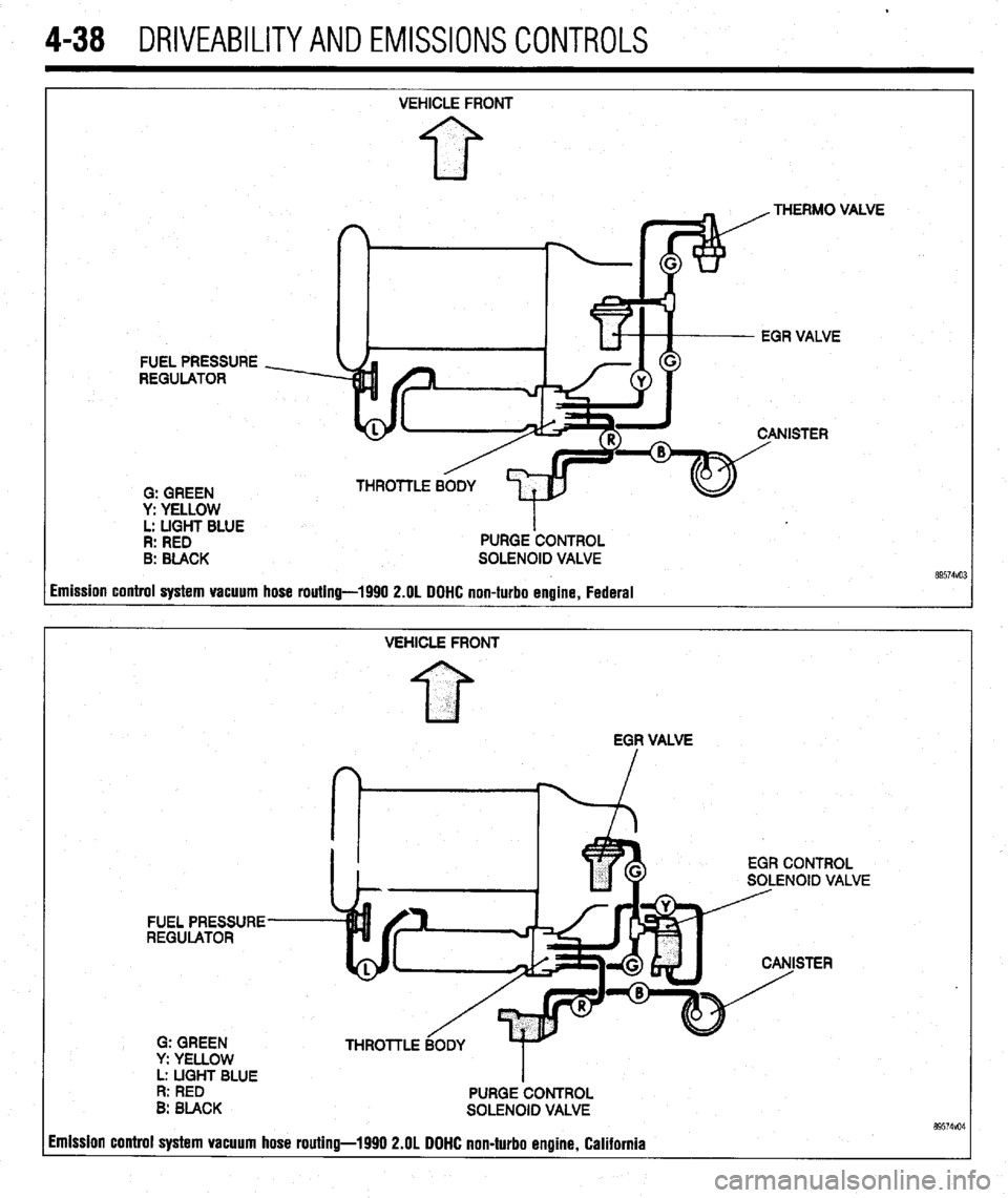
FUEL PRESSURE
REGULATOR
0: GREEN
y: YELLOW
L: LIGHT BLUE
R: RED
B: BLACK VEHICLE FRONT
PURGE ‘CONTROL
SOLENOID VALVE .VE
imission control system vacuum hose routing-1990 2.OL DOHC non-turbo engine, Federal
VEHICLE FRONT
EGF VALVE
EGR CONTROL
SOLENOID VALVE
FUEL PRESSURE
REGULATOR
STER
G: GREEN
y: YELLOW
L: UGHT BLUE
I
R: RED
PURGE CONTROL
B: BLACK
SOLENOID VALVE 89574vo4 imission control system vacuum hose routing-1990 2.OL DOHC non-turbo engine, California
Page 182 of 408
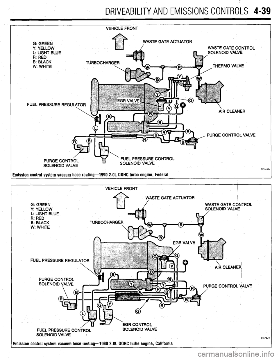
.
DRIVEABILITYAND EMISSIONS CONTROLS 4-39
VEHICLE FRONT
FI
Emission control system vacuum hose routing-1990 2.OL DOHC turbo engine, Federal
VEHICLE FRONT I
STE GATE ACTUATOR
G: GREEN
y: YELLOW LENOID VALVE
L: LIGHT BLUE
R: RED
B: BLACK TURBOCHARGE
w: WHITE
FUEL PRESSURE REGU
RGE CONTROL VALVE
FUEL PRESSURE CO OLENOID VALVE
SOLENOID VALVE I
Emission control system vacuum hose routing-1990 2.OL DOHC turbo engine, California
89574VO6
Page 183 of 408
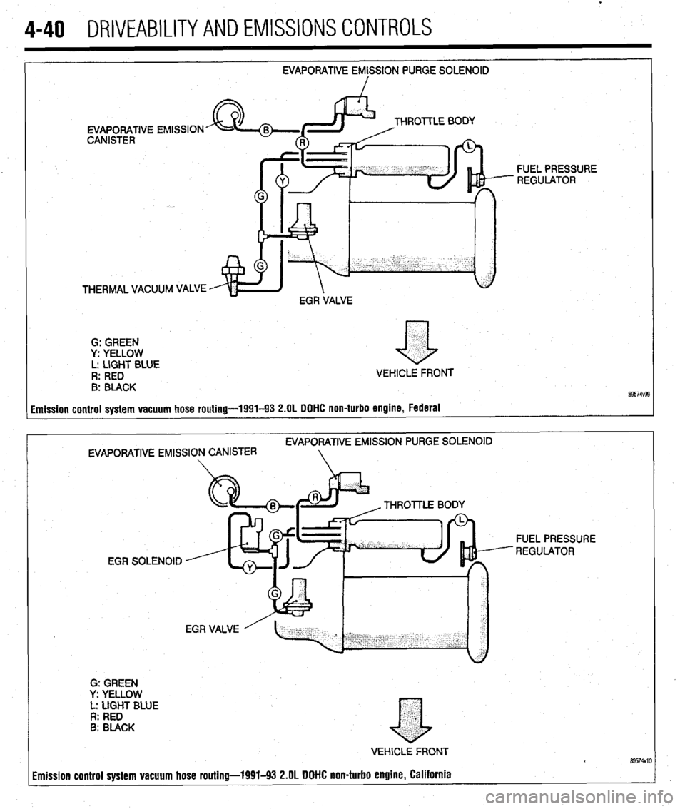
4-40 DRIVEABILITYAND EMISSIONS CONTROLS
EVAPORATIVE EMISSION PURGE SOLENOID
I
EVAPORATIVE
CANISTER THROlTLE BODY
THERMAL VACUUM VALVE $d yEAt FUEL PRESSURE
- REGULATOR
G: GREEN
y: YELLOW
L: LIGHT BLUE
R: RED VEHICLE FRONT
8: BLACK
imission control system vacuum hose routing-1991-93 2.OL DOHC non-turbo engine, Federal
EVAPORATIVE EMlSSlON PURGE SOLENOID
EVAPORATIVE EMISSION CANISTER
G: GREEN
Y: YELLOW
L: UGHT BLUE
R: RED
B: BLACK THROllLE 80
EGR SOLENOID FUEL PRESSURE
REGULATOR
.
a
VEHlCLE FRONT Bs574VlO imission control system vacuum hose routing-1991-93 2.OL DOHC non-turbo engine, California
Page 184 of 408
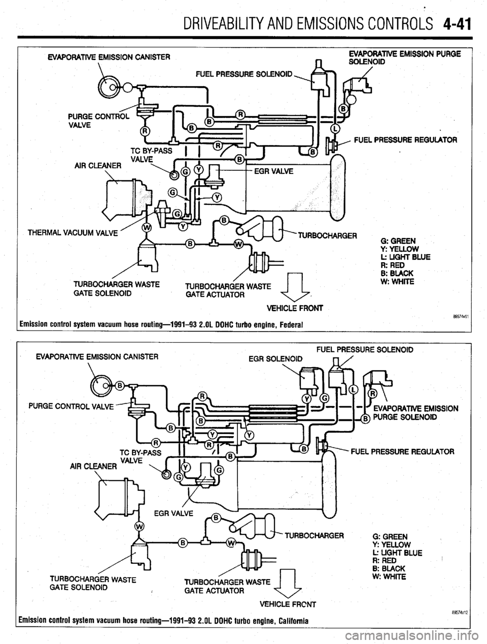
.
DRIVEABILITYAND EMISSIONS CONTROLS 4-41
EVAPORATIVE EMISSION PURGE
FUEL PRESSURE SOLENOID
THERMAL FUEL PRESSURE REGULATOR
AlRC
VACUUM VALVE
TURBOCHARGER
G: GREEN
y: YELLOW
L: UGHT BLUE
R: RED
B: BLACK
w: WHlTE
TURBOCHARGER WASTE P
TURBOCHARGER WASTE
GATE SOLENOID
GATE ACTUATOR
a
VEHlCLi FRONT
89574Vll Imission control system vacuum hose routing-1991-93 2.OL DDHC turbo engine, Federal
FUEL PRESSURE SOLENOID
EVAPORATlVE EMISSION CANISTER
EGR SOLENOID
PURGE CONTROL VALVE
ORATlVE EMISSION
PURGE SOLENOID
FUEL PRESSURE REGULATOR
TURBOCHARGER
0: GREEN
Y: YELLOW
Lz UGHT BLUE
R: RED
8: BLACK
TURBOCHARGER WASTE
GATE ACTUATOR
VEHICLE FRCNT
Imission control system vacuum hose routing-1991-93 2.OL DOHC turbo engine. California w: WHITE
a9574vi;
Page 186 of 408
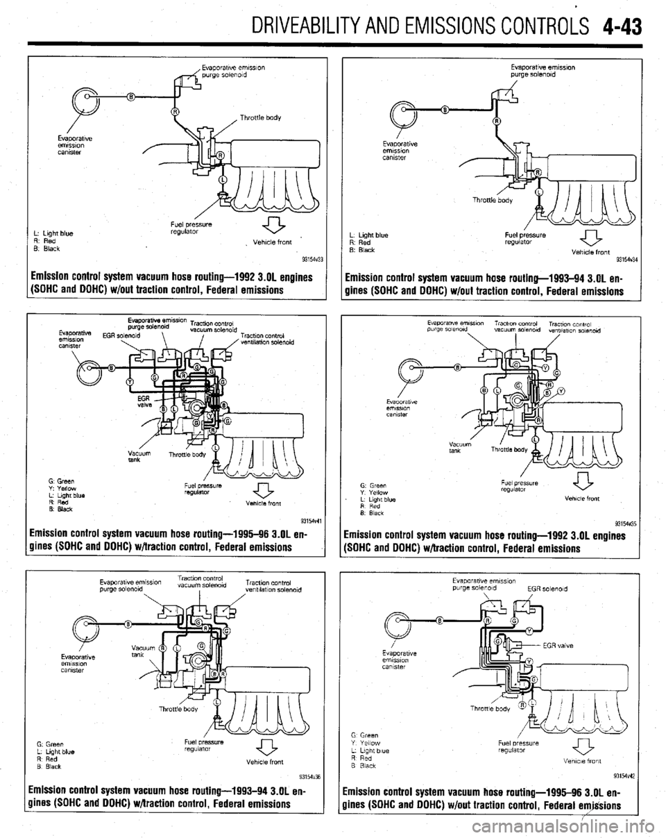
DRIVEABILITYAND EMISSIONSCONTROL-S 4-43
L. Light blue
R. Red
B Black Fuel pressure
regulator
. Vehicle front
93154~33
I Fuel pressure
regulator
Vehicle front
93154V34
Emission control system vacuum hose routing-1992 3.01 engines
Emission control system vacuum hose routing-1993-94 3.OL en-
(SOHC and OOHC) w/out traction control, Federal emissions
gines (SOHC and DOHC) w/out traction control, Federal emissions
R’ Red
0. Black Venlcle front
9315-M
Emission control system vacuum hose routing-1996-96 3.OL en-
gines (SOHC and DOHC) w/traction control, Federal emissions
Evaporatwe em~smn Traction control
vacuum so&old Tracuon control
purge solmold
, ,ventllatlon solmold
Emission control system vacuum hose routing-1993-94 3.OL en-
Evaporatwe ernmon
purge solenoid
L Light blue
R Red
B Black
Fuel pressure
regulator
Vehicle front
931W3E
imission control system vacuum hose routing-1992 3.OL engines
SOHC and DOHC) w/traction control, Federal emissions
Evaporawe emss~on
purge solenoid
EGR solmold
G Green
Y Yellow
L L,gnt blue
R Red
B 3lack Fuel oressure
regUlatOr
Vetme front
93154v42
imission control system vacuum hose routing-1995-96 3.OL en-
lines (SOHC and DOHC) w/out traction control, Federal emjgsions