1900 MITSUBISHI DIAMANTE open hood
[x] Cancel search: open hoodPage 15 of 408
*
l-16 GENERALINFORMATIONAND MAINTENANCE
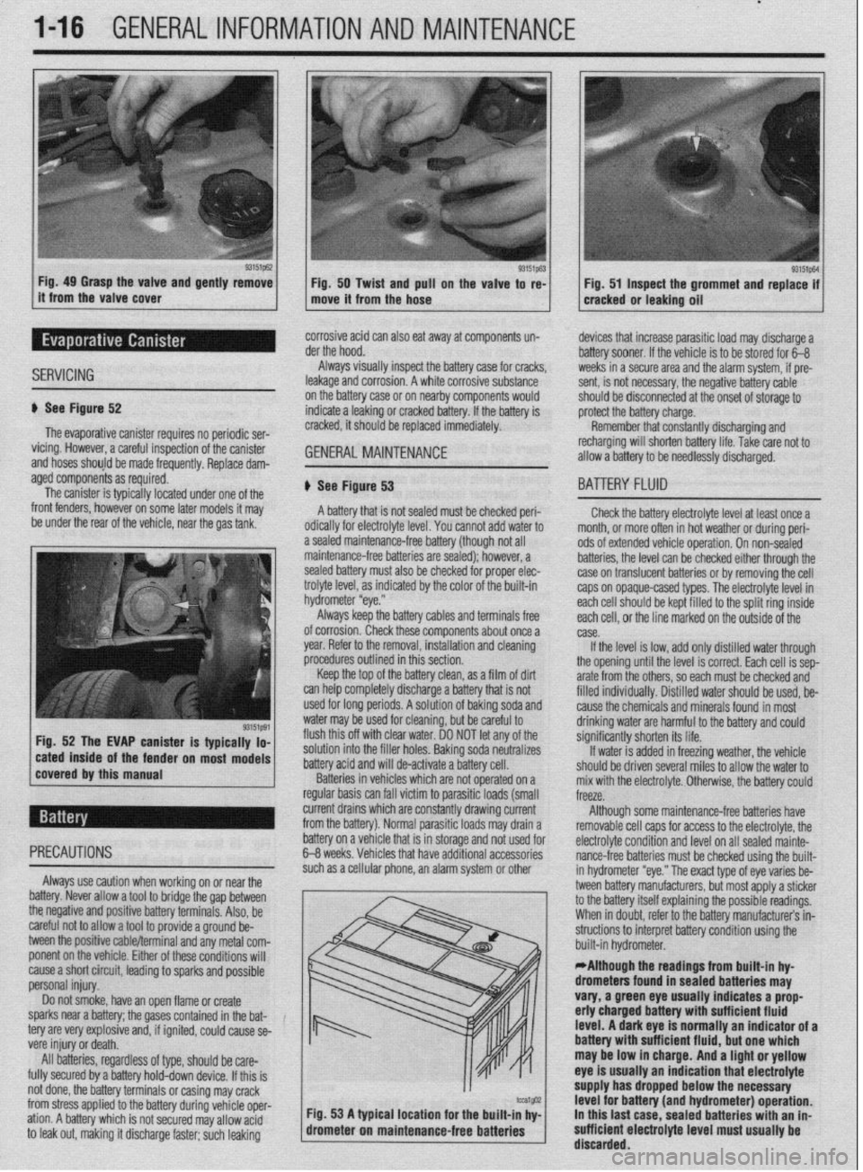
Fig. 49 Grasp the valve and gently remove
Fig. 50 Twist and pull on the valve to re-
it from the valve cover
move it from the hose Fig. 51 Inspect the grommet and replace if
cracked or leaking oil
SERVICING
corrosive acid can also eat away at components un-
der the hood.
Always visually inspect the battery case for cracks,
leakage and corrosion. A white corrosive substance
u See Figure 52
The evaporative canister requires no periodic ser-
vicing. However, a careful inspection of the canister
and hoses should be made frequently, Replace dam- on the battery case or on nearby components would
indicate a leaking or cracked battery. If the battery is
cracked, it should be replaced immediately. GENERALMAINTENANCE '_
devices that increase parasitic load may discharge a
battery sooner. If the vehicle is to be stored for 6-B
weeks in a secure area and the alarm system, if pre-
sent, is not necessary, the negative battery cable
should be disconnected at the onset of storage to
protect the battery charge.
Remember that constantly discharging and
recharging will shorten battery life. Take rare not to
allow a battery to be needlessly discharged.
aged components as required.
The canister is typically located under one of the
front fenders, however on some later models it may
be under the rear of the vehicle, near the gas tank,
r on most models # See Figure 53
A battery that is not sealed must be checked peri-
odically for electrolyte level. You cannot add water to
a sealed maintenance-free battery (though not all
maintenance-free batteries are sealed); however, a
sealed battery must also be checked for proper elec-
trolyte level, as indicated by the color of the built-in
hydrometer “eye.”
Always keep the battery cables and terminals free
of corrosion. Check these components about once a
year. Refer to the removal, installation and cleaning
procedures outlined in this section,
Keep the top of the battery clean, as a film of dirt
can help completely discharge a battery that is not
used for long periods. A solution of baking soda and
water may be used for cleaning, but be careful to
flush this off with clear water. DO NOT let any of the
solution into the filler holes. Baking soda neutralizes
battery acid and will de-activate a battery cell.
Batteries in vehicles which are not operated on a
regular basis can fall victim to parasitic loads (small
BA-ITERY FLUID
Check the battery electrolyte level at least once a
month. or more often in hot weather or during peri-
ods of extended vehicle operation. On non-sealed
batteries, the level can be checked either through the
case on translucent batteries or by removing the cell
caps on opaque-cased types. The electrolyte level in
each cell should be kept filled to the split ring inside
each ceil, or the line marked on the outside of the
case.
If the level is low, add only distilled water through
the opening until the level is correct. Each cell is sep-
arate from the others, so each must be checked and
filled individuallv. Distilled water should be used, be-
cause the chemicals and minerals found in most
drinking water are harmful to the battery and could
significantly shorten its life.
If water is added in freezing weather, the vehicle
should be driven several miles to allow the water to
mix with the electrolyte. Otherwise, the battery could
freeze.
current drains which are constantly drawing current
from the battery). Normal parasitic loads may drain a Although some maintenance-free batteries have
removable cell caos for access to the electrolyte, the
cause a short circuit, leading to sparks and possible
personal injury.
Do not smoke, have an open flame or create
sparks near a battery; the gases contained in the bat-
tery are very explosive and, if ignited, could cause se-
vere injury or death.
All batteries, regardless of type, should be care-
fully secured by a battery hold-down device. If this is
not done, the battery terminals or casing may crack
from stress applied to the battery during vehicle oper-
ation. A battery which is not secured may allow acid
to leak out, making it discharge faster; such leaking m / built-in hydrometer. .
*Although the readings from built-in hy-
drometers found in sealed batteries may
vary, a green eye usually indicates a prop
erly charged battery with sufficient fluid
level. A dark eye is normally an indicator of a
battery wlth sufficient fluid, but one which
may be low in charge. And a light or yellow
eye is usually an indication that electrolyte
supply has dropped below the necessary
tcu1@32 Fig. 53 A typical location for the built-in hv- level for battery (and hydrometer) operation.
drometer on maintenan
ce-free batteries ’ I In this last case. sealed batteries with an in-
sufficient electrolyte level must usually be
’ discarded.
Page 33 of 408
.
l-34 GENERALINFORMATIONAND MAINTENANCE
Engine oil level should be checked every time you
put fuel in the vehicle or are under the hood perform- miles of highway driving. Fluid which is warmed to
normal operating temperature will flow faster, drain
ing other maintenance.
1. Park the vehicle on a level surface.
2. The enaine mav be either hot or cold when
, if it is hot, wait a few min- checking oil level. The EPA warns that prolonged contact with
used engine oil may cause a num’ * * *
dianrAnrr inrldinn ranrnrl V#lll more completely and remove more contaminants
frnm tho clnnine
utes after the engine has been turned OFF to allow the
oil to drain back into the crankcase. If the engine is
cold, do not start it before checking the oil level. point on the oil pan. If not, you may have to raise the
vehicle slightly higher on one jackstand (side) than
3. Open the hood and locate the engine oil dip-
stick. Pull the dipstick from its tube, wipe it clean,
and reinsert it. Make sure the diDstick is fullv in-
serted.
4. Pull the dipstick from its tube again. Holding it to used engin
be worn whet
handsandan
so*m ..#a . . . . .
IDer 01 SKlll u,yu,u=,+, ,,,u,uu,,,u uu,,u=, i , vu should
uff art to minimize your exposure
le oil. Protective gloves should
1 changing the oil. Wash your
y other exposed skin areas as
111 aJ vv4ble after exposure to used en-
m nil St-mn mwl w&or nr umtarlncr hand gin Y “II. ““up “ll” .,U.“I, “rn W.Y.“. .““I .I....” cleaner should be used.
horizontally, read the oil level. The oilshould be be-
tween the MIN and MAX marks or the notches on the
dipstick. If the oil is below the MIN mark or lower
notch, add oil of the proper viscosity through the
capped opening of the valve cover. *The engine oil and oil filter should be
changed at the recommended intervals on
the Maintenance Chart. Though some manu-
facturers have at times recommended chang-
ing the filter only at every other oil change, ’
Chilton recommends that you always change
ll”,,, Cl>” ““y”‘“. 1. Raise and support the vehicle safely on jack-
stands. Make sure the oil drain olua is at the lowest
the other.
2. Before you crawl under the vehicle, take a look
at where you will be working and gather all the nec-
essary tools, such as a few wrenches or a ratchet and
strip of sockets, the drain pan, some clean rags and,
if the oil filter is more accessible from underneath the
vehicle, you will also want to grab a bottle of oil, the
new filter and a filter wrench at this time.
5. Reolace the diostick. and check the level aaain
. The benefit of fresh oil
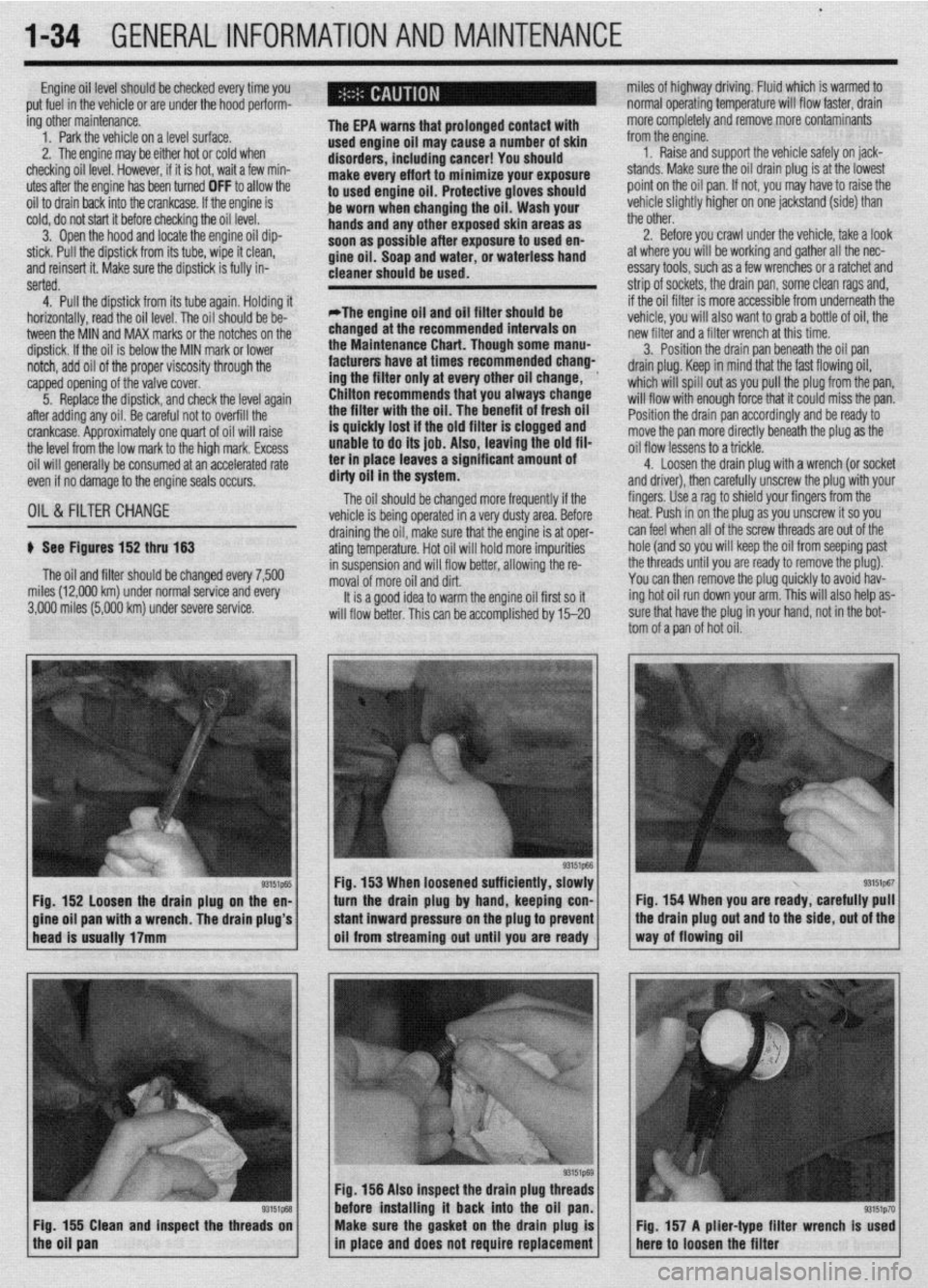
p See Figures 152 thru 153
The oil and filter should be changed every 7,500
miles (12,000 km) under normal service and every
3,000 miles (5,000 km) under severe service.
93151p-55 Fig. 152 loosen the drain plug on the en-
a wrench. The drain plug’s 3. Position the drain pan beneath the oil pan
drain plug. Keep in mind that the fast flowing oil,
which will spill out as you pull the plug from the pan,
will flow with enough force that it could miss the pan.
Position the drain pan accordingly and be ready to
move the pan more directly beneath the plug as the
oil flow lessens to a trickle.
4. Loosen the drain ~lua with a wrench (or socket
and driver), then carefuliy unscrew the plug with your
fingers. Use a rag to shield your fingers from the
heat. Push in on the plug as you unscrew it so you
draining the oil, make sure that the engine is at oper- can feel when all of the screw threads are out of the
ating temperature. Hot oil will hold more impurities hole (and so you will keep the oil from seeping past
in suspension and will flow better, allowing the re- the threads until you are ready to remove the plug).
moval of more oil and dirt. You can then remove the plug quickly to avoid hav-
It is a good idea to warm the engine oil first so it ing hot oil run down your arm. This will also help as-
will flow better. This can be accomolished bv 15-20 sure that have the plug in your hand, not in the bot-
tom of a pan of hot oil.
Fig. 153 When loosened sufficiently, slowly
turn the drain plug by hand, keeping con- Fig. 154 When you are ready, carefully pull
Fig. 156 Also inspect the drain plug th
before installing it back into the oil
Fig. 155 Clean and inspect the threads on
the oil pan Make sure the gasket on the drain plug is
in place and does not require replacement Fig. 157 A plier-type filter wrench Is used
here to loosen the filter
Page 35 of 408
.
l-36 GENERALINFORMATIONAND MAINTENANCE
Install the drain plug and tighten to 22 ft. Ibs.
(304Nm)
5. Refill the transaxle to the proper level, as
shown in the Capacities chart, with the appropriate
fluid. The oil level should be at the bottom of the oil
filler hole. I
6. When the oil reaches the orooer level, install
the filler plug and tighten to 22 ft. Ibs. (30 Nm).
FLUID RECOMMENDATIONS
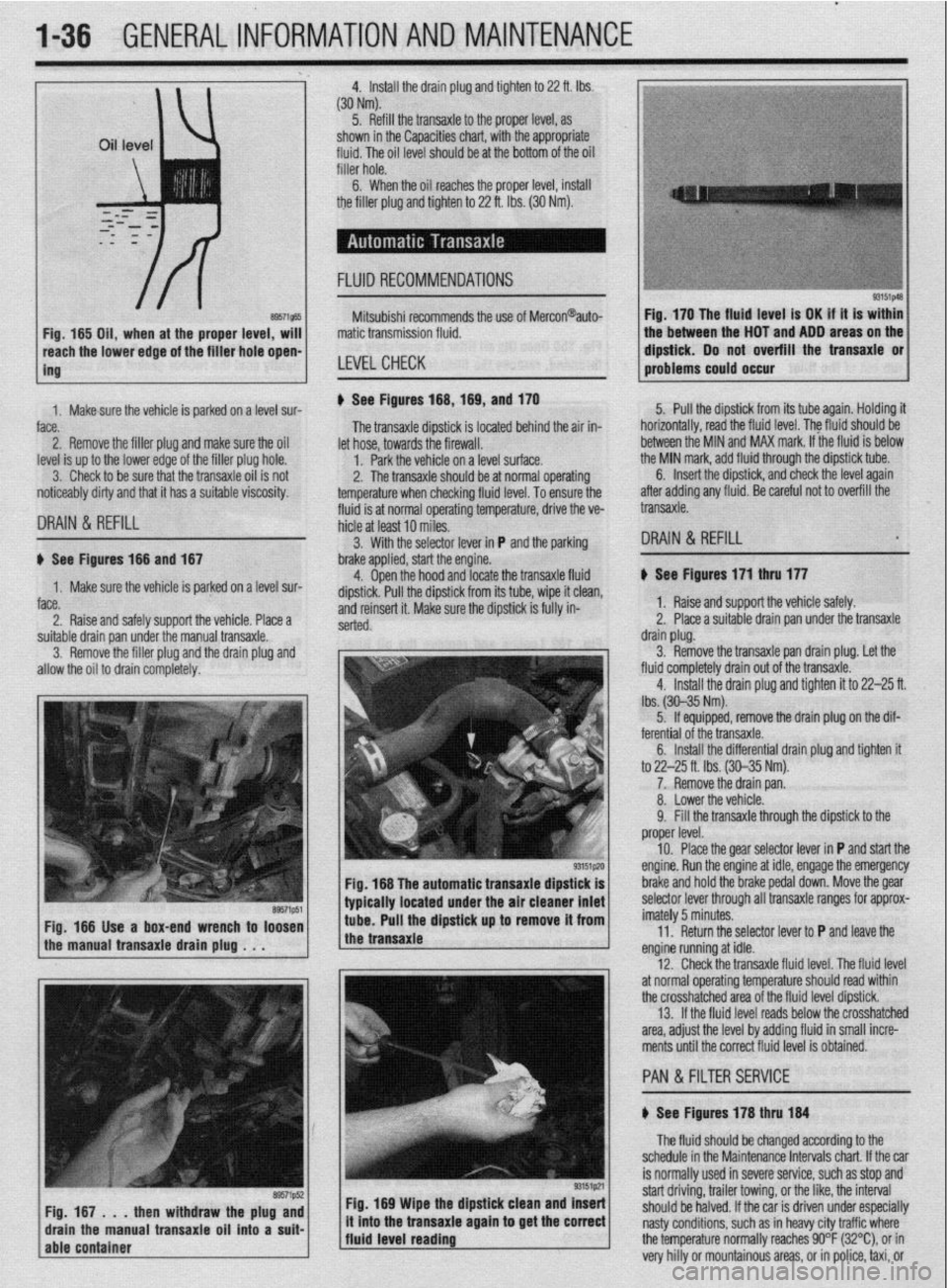
8957i565 Fig, 165 Oil, when at the proper level, will
reach the lower edge of tC=+ frfr*r u*rn -non-
ing Mitsubishi recommends the use of Mercon@auto-
matic transmission fluid.
LEVELCHECK
Fig. 170 The fluid level is OK if it is within
the between the HOT and ADD areas on the
&&i& Do not overfill the transaxle or
-.*".."... -- .*"- problems could o ccur
1. Makesure the vehicle is oarked on a level sur-
face.
2. Remove the filler plug and make sure the oil
level is up to the lower edge of the filler plug hole.
3. Check to be sure that the transaxle oil is not
noticeably dirty and that it has a suitable viscosity. u See Figures 168,169, and 170
fluid is at normal operating temperature, drive the ve- The transaxle dipstick is located behind the air in-
hicle at least 10 miles. let hose, towards the firewall.
1. Park the vehicle on a level surface.
2. The transaxle should be at normal operating
temperature when checking fluid level. To ensure the 5. Pull the dipstick from its tube again. Holding it
horizontally, road the fluid level. The fkrid should be
between the MIN and MAX mark. If the fluid is below
the MIN mark, add fluid through the dipstick tube.
DRAIN & REFILL
6. Insert the dipstick, and check the level again
after adding any fluid. Be careful not to overfill the
transaxle.
3. With the selector lever in P and the parking
DRAIN & REFILL u See Figures 166 and 167
1. Make sure the vehicle is parked on a level sur-
face.
2. Raise and safely support the vehicle. Place a brake applied, start the engine.
4. Open the hood and locate the transaxle fluid
dipstick. Pull the dipstick from its tube, wipe it clean,
and reinsert it. Make sure the dipstick is fully in-
serted.
suitable drain pan under the manual transaxle.
3. Remove the filler plug and the drain plug and
allow the oil to drain completely.
Fig. 166 The automatic transaxle dipstick is
typically located under the air cleaner inlet
Fig. 166 Use a box-end wrench to loosen
the manual transaxle drain plug . . . tube. Pull the dipstick up to remove it from
the transaxle
Fig. 169 Wipe the dipstick clean and Insert
/fluid level reading ., it mto the transaxle agam to get the correct
j The fluid should be changed according to the
schedule in the Maintenance Intervals chart. If the car
is normally used in severe service, such as stop and
start driving, trailer towing, or the like, the interval
should be halved. If the car is driven under especially
nasty conditions, such as in heavy city traffic where
the temperature normally reaches 90°F (32%), or in
very hilly or mountainous areas, or in police, taxi, or b See Figures 171 thru 177
1. Raise and support the vehicle safely.
2. Place a suitable drain pan under the transaxle
drain plug.
3. Remove the transaxle pan drain plug. Let the
fluid completely drain out of the transaxle.
4. Install the drain plug and tighten it to 22-25 ft.
lbs. (30-35 Nm).
5. If equipped, remove the drain plug on the dif-
ferential of the transaxle.
6. Install the differential drain plug and tighten ft
to 22-25 ft. Ibs. (30-35 Nm).
7. Remove the drain pan.
8. Lower the vehicle.
9. Fill the transaxle through the dipstick to the
proper level.
10. Place the gear selector lever in P and start the
engine. Run the engine at idle, engage the emergency
brake and hold the brake pedal down. Move the gear
selector lever through all transaxle ranges for approx-
imately 5 minutes.
11. Return the selector lever to P and leave the
engine running at idle.
12. Check the transaxle fluid level. The fluid level
at normal operating temperature should read within
the crosshatched area of the fluid level dipstick.
13. If the fluid level reads below the crosshatched
area, adjust the level by adding fluid in small incre-
ments until the correct fluid level is obtained.
PAN &FILTER SERVICE
b See Figures 178 thru 184
Page 40 of 408
.
GENERALINFORMATIONAND MAINTENANCE l-41
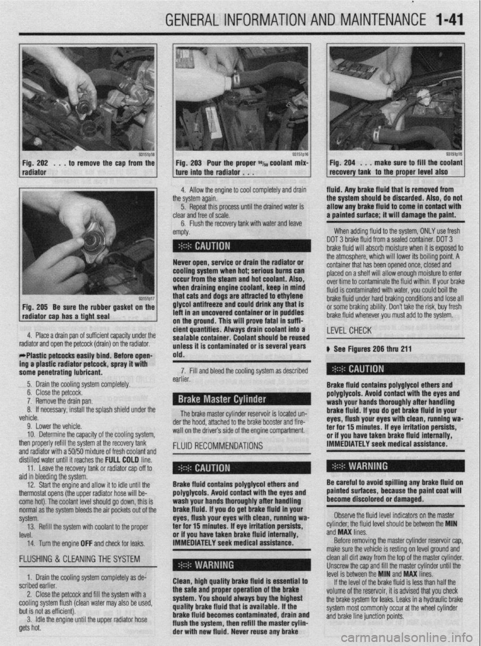
93151p18 Fig. 202 . , . to remove the cap from the
radiator
93151p17 Fig. 205 Be sure the rubber gasket on the
radiator cap has a tight seal e Fig. 203 Pour the proper *I~ coolant mix- 1 Fig. 204 . . . make sure to fill the coolant
recovery tank to the proper level also ture into the radiator . . .
.I
4. Allow the engine to cool completely and drain fluid. Any brake fluid that is removed from
ie system again.
5. Repeat this processuntil the drained water is
lear
and free of scale.
6. Flush the recovery tank with water and leave ’
mpty. the system should be discarded. Also, do not
allow any brake fluid to come in contact with
a painted surface; it will damage the paint.
When adding fluid to the system, ONLY use fresh
DOT 3 brake fluid from a sealed container. DOT 3
brake fluid will absorb moisture when it is exposed to
.a . . . , .*a. . . * .*. . .
- Never open, service or drain the radiator or
cooling system when hot; serious bums can
occur from the steam and hot coolant. Also,
when draining engine coolant, keep In mind
that cats and dogs are attracted to ethylene
glycol antifreeze and could drink any that is
left in an uncovered container or in puddles
on the ground. This will prove fatal in suffi-
4. Place a drain pan of suff i ’ 1 . . . ..I .I. 1,~ cient quantities. Always tne atmospnere, wnrcn wnr rower 1r.s oourng pomr. A
container that has been opened once, closed and
placed on a shelf will allow enough moisture to enter
over time to contaminate the fluid within. If your brake
fluid is contaminated with water, you could boil the
brake fluid under hard braking conditions and lose all
or some braking ability. Don’t take the risk, buy fresh
brake fluid whenever you must add to the system.
crenr capacrry unaer me
drain) on the radiator.
rrrasuc perwcss easuy bind; Before open-
ing a plastic radiator petcock, spray it with
some penetrating lubricant. drain coolant into a
earner. sealable container. Coolant should be reused
unless it is contaminated or is several years
old.
The brake master cylinder ~a~~~~r,~~ :A I~nnL.4 n-n 7. Fill and bleed the cooling system as described
Brake fluid contains polyglycol ethers and
polyglycols. Avoid contact with the eyes and ,LEVEL CHECK
wash your hands thoroughly after handling
brake fluid. If vou do oet brake fluid in vour
eyes, flush your eyeswith clean, runniug wa-
a-.. ‘Y-- ar -l-..n-- II -.._ I____ k See Figures 206 thru 211
.a-11-- - __-PA._ radiator and open the petcock (
- w&1--x3_ --mm.._..- . . ..-I...
5. Drain the cooling system completely.
6. Close the petcock.
7. Remove the drain pan.
If necessary, install the splash shield under the 8.
L.-l
venicie.
9. Lower the vehicle.
10. Determine the capacity of the cooling system,
then properly refill the system at the recovery tank
and radiator with a 50/50 mixture of fresh coolant and
fKm”“ll 15 IUMLC” “II- brake booster and fire- der the hood, attached to the
wall on the drivers side of the engine compartment.
FLUID RECOMMENDATIONS rer mr 13 mmures. IT eye irriIauon persim, or if you have taken brake fluid internally,
IMMEDIATELY seek medical assistance.
ala in oreerring me sysrem.
12. Start the engine and allow it to idle until the
thermostat opens (the upper radiator hose will be-
come hot). The coolant level should go down, this is
normal as the system bleeds the air pockets out of the
svstem.
IRVf!l ._._. 14. Turn the engine OFF and check for leaks. IMMEDIATELY seek medical assistance.” Brake fluid contains polyglycol ethers and
polyglycols. Avoid contact with the eyes and
wash your hands thoroughly after handling
brakefluid. If you do get brake fluid in your
eyes, flush your eyes with clean, running wa-
or if vou have taken brake fluid internallv.
Before removing the master cylinder reservoir cap,
make sure the vehicle is resting on level ground and Be careful to avoid spilling any brake fluid on
painted surfaces, because the paint coat will
become discolored or damaged.
Observe the fluid level indicators on the master
._ ._ __
‘eve1 should be between the MIN
ano
ivw unes. 13. Refill the system with coolant to the proper ter for 15 minutes; If eye irritation persists, cylinder; the tluld II
..J ..I” I....
FLUSHING & CLEANINGTHE SYSTEM
1. Drain the cooling system completely as de:
scribed earlier.
2. Close the petcock and fill the system with a
cooling system flush (clean water may also be used,
but is not as efficient).
3. Idle the engine until the upper radiator hose
gets hot. Clean, high quality brake fluid is essential to
the safe and proper operation of the brake
system. You should always buy the highest
quality brake fluid that is available. If the
brake fluid becomes contaminated, drain and
flush the system, then refill the master cylin-
der with new fluid. Never reuse any brake clean all dirt away from the top of the master cylinder.
Unscrew the cap and fill the master cylinder until the
level is between the MIN and MAX lines.
If the level of the brake fluid is less than half the
volume of the reservoir, it is advised that you check
the brake system for leaks. Leaks in a hydraulic brake
system most commonly occur at the wheel cylinder
and brake line junction points.
Page 63 of 408
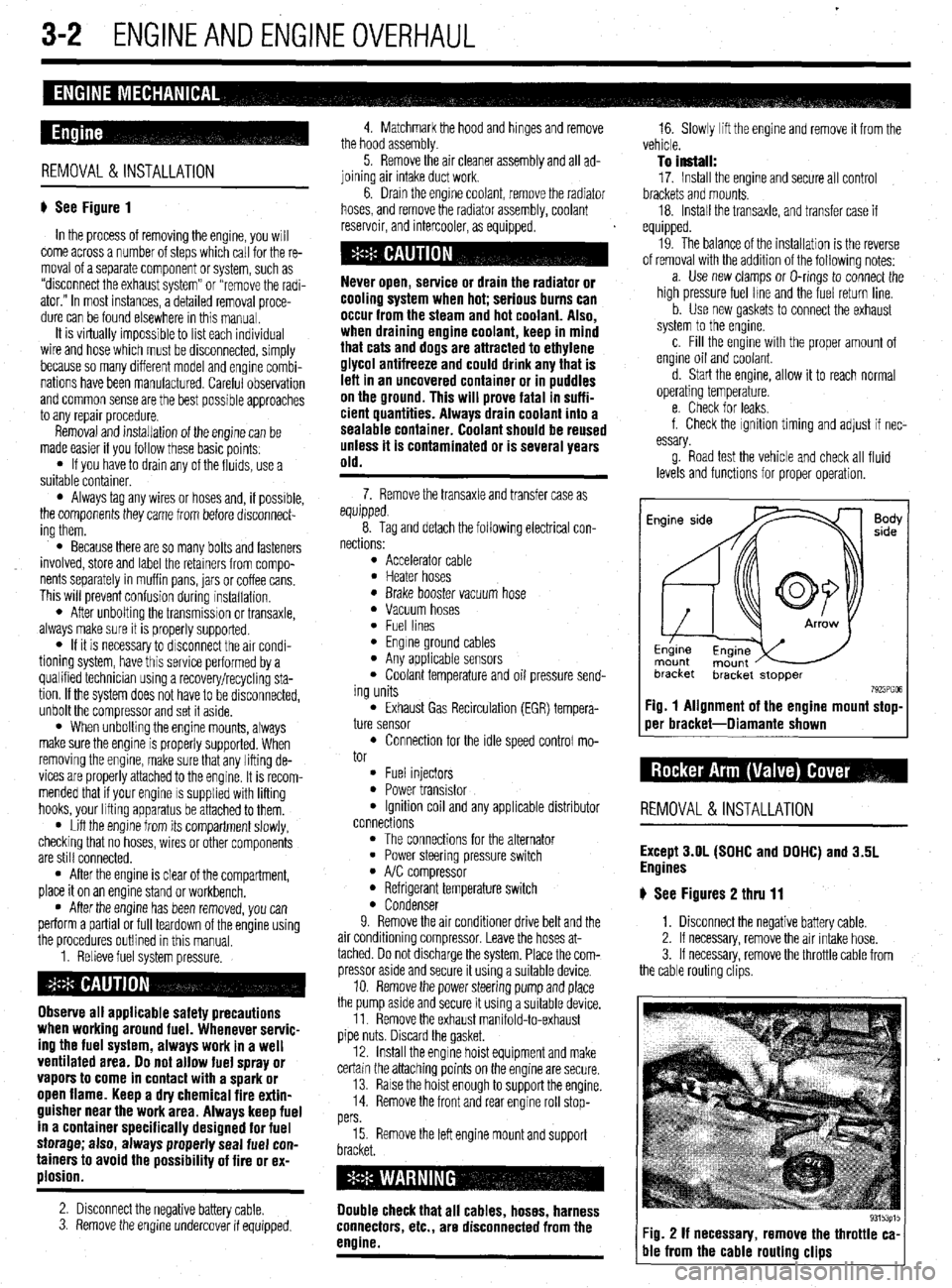
3-2 ENGINEANDENGINEOVERHAUL
REMOVAL &INSTALLATION
# See Figure 1
In the process of removing the engine, you will
come across a number of steps which call for the re-
moval of a separate component or system, such as
“disconnect the exhaust system” or “remove the radi-
ator.” In most instances, a detailed removal proce-
dure can be found elsewhere in this manual.
It is virtually impossible to list each individual
wire and hose which must be disconnected, simply
because so many different model and engrne combi-
nations have been manufactured Careful observation
and common sense are the best possible approaches
to any repair procedure.
Removal and installation of the engine can be
made easier if you follow these basic points:
l If you have to drain any of the fluids, use a
suitable container.
l Always tag any wires or hoses and, if possrble,
the components they came from before disconnect-
ing them.
l Because there are so many bolts and fasteners
involved, store and label the retainers from compo-
nents separately in muffin pans, jars or coffee cans.
This will prevent confusion during installatron.
l After unbolting the transmisston or transaxle,
always make sure it is properly supported.
l If it is necessary to disconnect the air condi-
tioning system, have this service performed by a
qualified technician using a recovery/recycling sta-
tion If the system does not have to be disconnected,
unbolt the compressor and set it aside.
l When unbolting the engine mounts, always
make sure the engine is properly supported. When
removing the engine, make sure that any lifting de-
vices are properly attached to the engine. It is recom-
mended that if your engine IS supplied with lifting
hooks, your lifting apparatus be attached to them.
l Lift the engine from its compartment slowly,
checking that no hoses, wires or other components
are still connected.
l After the engine is clear of the compartment,
place it on an engine stand or workbench.
l After the engine has been removed, you can
perform a partial or full teardown of the engine using
the procedures outlined in this manual.
1. Relieve fuel system pressure.
Observe all applicable safety precautions
when working around fuel. Whenever servic-
ing the fuel system, always work in a well
ventilated area. Do not allow fuel spray or
vapors to come in contact with a spark or
open flame. Keep a dry chemical fire extin-
guisher near the work area. Always keep fuel
in a container specifically designed for fuel
storage; also, always properly seal fuel con-
tainers to avoid the possibility of fire or ex-
plosion.
2. Disconnect the negative battery cable.
3. Remove the engine undercover if equipped. 4. Matchmark the hood and hinges and remove
the hood assembly.
5. Remove the air cleaner assembly and all ad-
joining air intake duct work.
6. Drain the engine coolant, remove the radiator
hoses, and remove the radiator assembly, coolant
reservoir, and intercooler, as equipped.
cooling system when hot; serious burns can
occur from the steam and hot coolant. Also,
when draining engine coolant, keep in mind
that cats and dogs are attracted to ethylene
glycol antifreeze and could drink any that is
left in an uncovered container or in puddles
on the ground. This will prove fatal in suffi-
cient quantities. Always drain coolant into a
sealable container. Coolant should be reused
unless it is contaminated or is several years
old.
7. Remove the transaxle and transfer case as
equipped.
8. Tag and detach the following electrical con-
nections:
l Accelerator cable l Heater hoses l Brake booster vacuum hose l Vacuum hoses l Fuel lines l Engine ground cables l Any applicable sensors l Coolant temperature and oil pressure send-
ing units
l Exhaust Gas Recirculation (EGR) tempera-
ture sensor
l Connection for the idle speed control mo-
tor
l Fuel injectors l Power transistor l Ignition coil and any applicable distributor
connections
l The connections for the alternator l Power steering pressure switch l A/C compressor l Refrigerant temperature switch l Condenser
9. Remove the air conditioner drive belt and the
air conditioning compressor. Leave the hoses at-
tached. Do not discharge the system. Place the com-
pressor aside and secure it using a suitable device.
10. Remove the power steering pump and place
the pump asrde and secure it using a surtable device.
11. Remove the exhaust manifold-to-exhaust
pipe nuts. Discard the gasket.
12. Install the engine hoist equipment and make
certain the attaching points on the engine are secure.
13. Raise the hoist enough to support the engine.
14. Remove the front and rear engine roll stop-
pers
15. Remove the left engine mount and support
Double check that all cables, hoses, harness
connectors, etc., are disconnected from the
engine.
16. Slowly lift the engine and remove it from the
vehicle.
To install:
17. Install the engine and secure all control
brackets and mounts.
18. Install the transaxle, and transfer case if
equipped.
19. The balance of the installation is the reverse
of removal with the addition of the following notes:
a. Use new clamps or O-rings to connect the
high pressure fuel lme and the fuel return line.
b. Use new gaskets to connect the exhaust
system to the engine.
c. Fill the engine with the proper amount of
engine oil and coolant.
d. Start the engine, allow it to reach normal
operating temperature.
e. Check for leaks.
f. Check the ignition timing and adjust if nec-
essary.
g. Road test the vehicle and check all fluid
levels and functions for proper operation.
Fig. 1 Alignment of the engine mount stop-
oer bracket-Diamante shown
REMOVAL &INSTALLATION
Except 3.OL (SOHC and DOHC) and 3.5L
Engines
# See Figures 2 thru 11
1. Disconnect the negative battery cable.
2. If necessary, remove the air intake hose.
3. If necessary, remove the throttle cable from
the cable routing clips.
Fig. 2 If necessary, remove the throttle ca-
ble from the cable routing clips
Page 214 of 408
CHASSIS ELECTRICAL 6-11
45. Install the heater hoses under the hood.
46. Install the mstrument panel by reversing its
removal procedure.
47. Install the center console.
48. install the upper and lower steering column
covers.
49. Install the center panel undercover.
50. Install the small column panel.
51. Install the steering wheel.
52. Fill the cooling system.
53. Connect the negative battery cable and check
the entire climate control system for proper operation
and leaks.
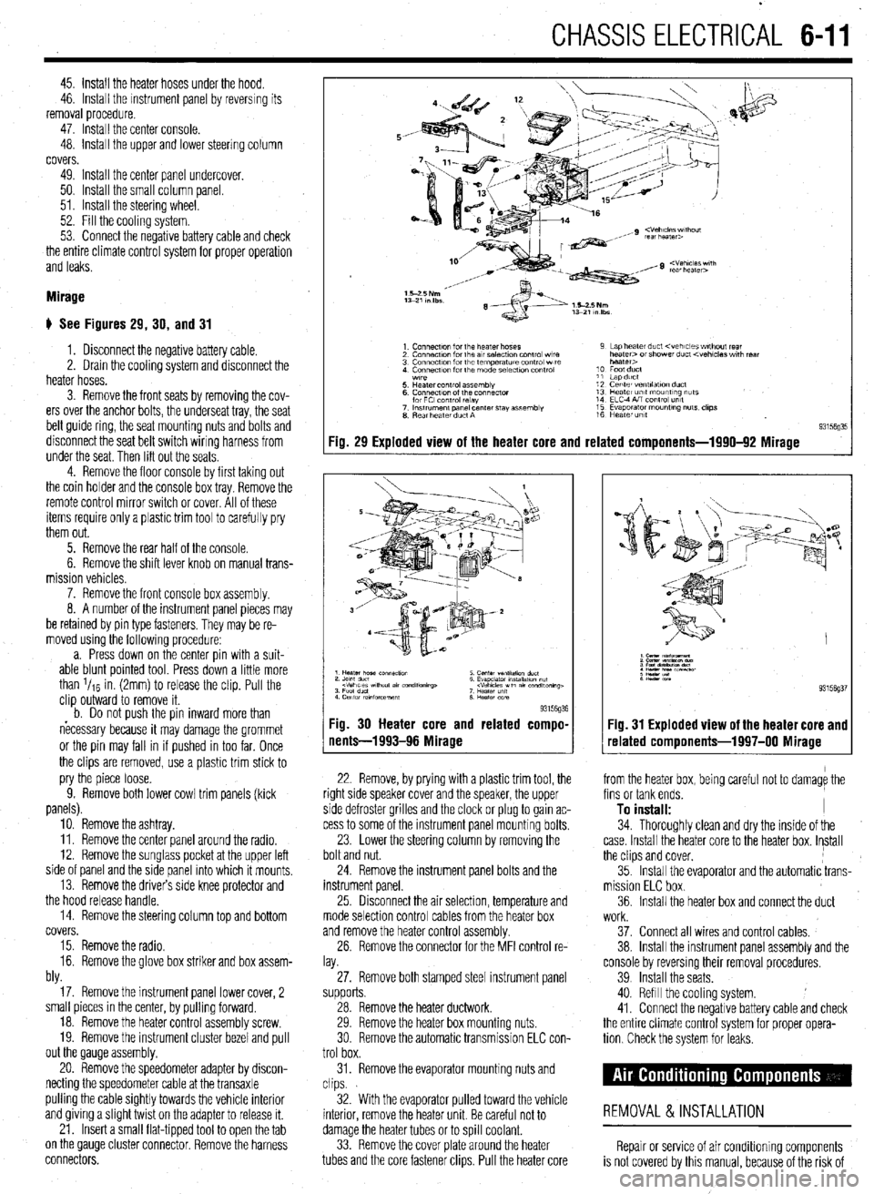
Mirage
# See Figures 29, 30, and 31
1. Disconnect the negative battery cable.
2. Drain the cooling system and disconnect the
heater hoses.
3. Remove the front seats by removing the cov-
ers over the anchor bolts, the underseat tray, the seat
belt guide ring, the seat mounting nuts and bolts and
disconnect the seat belt switch wiring harness from
under the seat. Then lift out the seats
4. Remove the floor console by first taking out
the coin holder and the console box tray. Remove the
remote control mirror switch or cover. All of these
items require only a plastic trim tool to carefully pry
them out.
5. Remove the rear half of the console.
6. Remove the shift lever knob on manual trans-
mission vehicles.
7. Remove the front console box assembly.
8. A number of the instrument panel pieces may
be retamed by pin type fasteners. They may be re-
moved using the following procedure:
a. Press down on the center pin with a suit-
able blunt pointed tool. Press down a little more
than l/re in. (2mm) to release the clip. Pull the
clip outward to remove it.
b. Do not oush the oin inward more than
necessary because it may damage the grommet
or the pin may fall in if pushed in too far. Once
the clips are removed, use a plastic trim stick to
pry the piece loose.
9. Remove both lower cowl trim panels (kick
panels).
10. Remove the ashtray.
11. Remove the center panel around the radio.
12. Remove the sunglass pocket at the upper left
side of panel and the side panel into which it mounts,
13. Remove the drivers side knee protector and
the hood release handle.
14. Remove the steering column top and bottom
covers.
15. Remove the radio.
16. Remove the glove box striker and box assem-
bly.
17. Remove the instrument panel lower cover, 2
small pieces in the center, by pulling forward.
18. Remove the heater control assembly screw.
19. Remove the instrument cluster bezel and pull
out the Qauge assembly.
20. Remove the speedometer adapter by discon-
necting the speedometer cable at the transaxle
pulling the cable Sightly towards the vehicle interior
and giving a Slight twist on the adapter to release it.
21. Insert a small flat-tipped tool to open the tab
on the QauQe cluster connector. Remove the harness
connectors.
Fig. 29 Exploded view of the heater core and related components-1990-92 Mirage
93l%Q% Fig. 30 Heater core and related compo-
nents-1993-96 Mirage
22. Remove, by prying with a plastic trim tool, the
right side speaker cover and the speaker, the upper
side defroster grilles and the clock or plug to gain ac-
cess to some of the instrument panel mounting bolts.
23. Lower the steering column by removing the
bolt and nut.
24. Remove the instrument panel bolts and the
instrument panel.
25 Drsconnect the air selection, temperature and
mode selection control cables from the heater box
and remove the heater control assembly.
26. Remove the connector for the MFI control re-
lay.
27. Remove both stamped steel instrument panel
supports.
28. Remove the heater ductwork.
29. Remove the heater box mounting nuts.
30 Remove the automatic transmission ELC con-
trol box.
31. Remove the evaporator mounting nuts and
clips.
32. With the evaporator pulled toward the vehicle
interior, remove the heater unit. Be careful not to
damage the heater tubes or to spill coolant.
33. Remove the cover plate around the heater
tubes and the core fastener clips. Pull the heater core 34. Thoroughly clean and dry the inside of the
case. Install the heater core to the heater box. Install
the clips and cover,
35. Install the evaporator and the automatic trans-
mission ELC box.
36. Install the heater box and connect the duct
Fig. 31 Exploded view of the heater core and
related components-1997-00 Mirage
from the heater box, being careful not to damage the
fins or tank ends.
To install: I
work.
37. Connect all wires and control cables,
38. Install the instrument panel assembly and the
console by reversmg their removal procedures.
39 Install the seats.
40. Refill the cooling system.
41. Connect the negative battery cable and check
the entire climate control system for proper opera-
tion Check the system for leaks.
REMOVAL &INSTALLATION
Repair or service of air Conditioning components
is not covered by this manual, because of the risk of
Page 222 of 408
CHASSIS ELECTRICAL 6-19
1. Disconnect the negative battery cable.
are all built into 1 multi-function combination
2. Remove the instrument cluster, as outlined 1. Disconnect the negative battery cable.
earlier in this section. switch that is mounted on the steering col-
2. Using a small screwdriver or other suitable
umn. Refer to Section 8 for procedures re-
3. Remove the retaining screws for the instrument tool, carefully pry the retaining clips from either side
garding the combination switch.
cluster lens and cover assembly. Remove the cover of the switch trim plate.
3.
and lens. Carefully pull the switch and trim plate out of
,
4. Remove the retaining screws for the gauge or the instrument panel.
4. Detach the electrical connectors and remove
warning lamp to be replaced, then remove the gauge
the switch.
or warning lamp.
REMOVAL&INSTALLATION : 5. The installation is the reverse of removal.
To install:
5. Place the gauge or warning lamp into place
and tighten the retaining screws. 1. Disconnect the negative battery cable.
6. Install the instrument cluster lens and cover 2. Using a suitable prytool, disengage the switch
assembly. retaining tabs.
REMOVAL &INSTALLATION 7. Install the instrument cluster. 3. Gently pull the switch from the instrument
8. Connect the negative battery cable. panel.
4. Detach the electrical connector and remove the *On all models the headlights, turn signals,
switch. and on some models, the cruise control func-
5. The installation is the reverse of removal. tion are all built into 1 multi-function combi-
nation switch that is mounted on the steerinq
REMOVAL &INSTALLATION column. Refer to Section 8 for procedures 6
garding the combination switch.
*The headlights, turn signals, dimmer
switch, horn switch, windshield
REMOVAL &INSTALLATION
wiper/washer, intermittent wiper switch and *
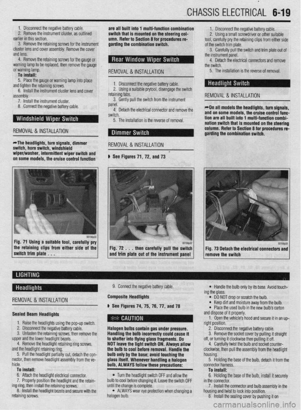
on some models, the cruise control function # See Figures 71, 72, and 73
the retaining clips from either side of the
switch trim plate . . . Fig. 72 . . . then carefully pull the switch
and trim plate out of the instrument panel Fig. 73 Detach the electrical connectors and
remove the switch
-
REMOVAL &INSTALLATION
Sealed Beam Headlights
1. Raise the headlights using the pop-up switch.
2. Disconnect the negative battery cable.
3. Unfasten the retaining screws, then remove the
upper and the lower headlight bezels.
4. Remove the headlight retaining ring screws,
and the headlight retaining ring.
5. Pull the headlight partially out, detach the con-
nectar, then remove headlight assembly from the ve-
hicle.
To install:
6. Attach the headlight electrical connector.
7. Properly position the headlight and the retain-
ing ring, then install the retaining screws.
8. Install the headlight bezels and secure with the
retaining screws. 9. Connect the negative battery cable.
Composite Headlights
6 See Figures 74, 75, 76, 77, anU78
Halogen bulbs contain gas under pressure.
Handling the
bulb incorrectly could cause it
to shatter into flying glass fragments. Do
NOT leave the light switch ON. Always allow
the bulb to cool before removal. Handle the
bulb only by the base; avoid touching the
glass itself. Whenever handling a halogen
bulb, ALWAYS follow these precautions:
l Turn the headlight switch OFF and allow the
bulb to cool before changing it. Leave the switch OFF
until the change is complete.
l ALWAYS wear eye protection when changing a
halogen bulb.
l Handle the bulb only by its base. Avoid touch-
ing the glass.
l DO NOT drop or scratch the bulb. l Keep dirt and moisture away from the bulb.
* Place the used bulb in the new bulb’s carton
and dispose of it properly.
1. Open the vehicle’s hood and secure it in an up-
right position.
2. Disconnect the negative battery cable.
3. Remove the socket cover by pulling it straight
off, or turning it clockwise then pulling it off.
4. Carefully twist the bulb and socket counter-
clockwise, then pull the assembly from the headlight
housing.
5. Holding the base of the bulb, detach it from the
connector harness.
To install:
6. Holding the base of the bulb, install it securely
in the connector.
7. Install the connector and bulb assembly in the
housing and twist to lock into position.
8. Install the sealing cover by pushing it on
Page 288 of 408
DRIVETRAIN 7-9
*When adjusting the clutch pedal height or
the clutch pedal clevis pin play, be careful
not to push the pushrod toward the master
cylinder.
d. Check that when the clutch pedal is de-
pressed all the way, the interlock switch switches
over from ON to OFF.
ADJUSTMENT
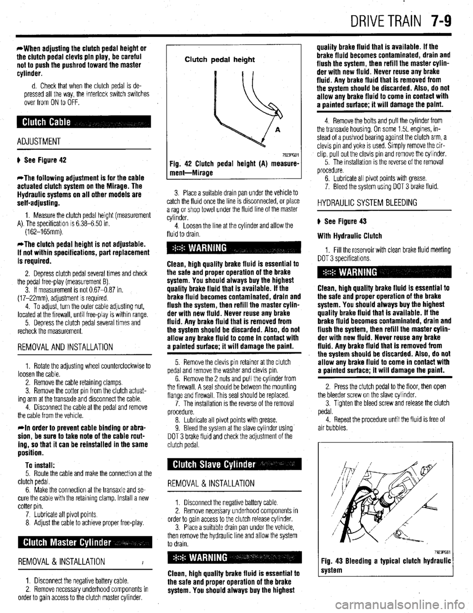
# See Figure 42
*The following adjustment is for the cable
actuated clutch system on the Mirage. The
Hydraulic systems on all other models are
self-adjusting.
1. Measure the clutch pedal height (measurement
A). The specificatron is 6.38-6.50 in.
(162-165mm).
*The clutch pedal height is not adjustable.
If not within specifications, part replacement
is required.
2. Depress clutch pedal several times and check
the pedal free-play (measurement B).
3. If measurement is not 0.67-0.87 in.
(17-22mm), adjustment is required.
4. To adjust, turn the outer cable adjusting nut,
located at the firewall, until free-play is within range.
5. Depress the clutch pedal several times and
recheck the measurement.
REMOVALANDINSTALLATION
1. Rotate the adjusting wheel counterclockwise to
loosen the cable.
2. Remove the cable retaining clamps.
3. Remove the cotter pin from the clutch actuat-
ing arm at the transaxle and disconnect the cable.
4. Disconnect the cable at the pedal and remove
the cable from the vehicle.
rln order to prevent cable binding or abra-
sion, be sure to take note of the cable rout-
ing, so that it can be reinstalled in the same
position.
To install:
5. Route the cable and make the connection at the
clutch pedal.
6. Make the connection at the transaxle and se-
cure the cable with the retaining clamp. Install a new
cotter pin.
7. Lubricate all pivot points.
8 Adjust the cable to achieve proper free-play.
REMOVAL &INSTALLATION
I
1. Disconnect the negative battery cable.
2. Remove necessary underhood components in
order to gain access to the clutch master cylinder.
Clutch pedal height
Fig. 42 Clutch pedal height (A) measure-
ment-Mirage
7923PGDl
3. Place a suitable drain pan under the vehicle to
catch the fluid once the line IS drsconnected, or place
a rag or shop towel under the fluid line of the master
cylinder.
4. Loosen the line at the cylinder and allow the
fluid to drain.
Clean, high quality brake fluid is essential to
the safe and proper operation of the brake
system. You should always buy the highest
quality brake fluid that is available. If the
brake fluid becomes contaminated, drain and
flush the system, then refill the master cylin-
der with new fluid. Never reuse any brake
fluid. Any brake fluid that is removed from
the system should be discarded. Also, do not
allow any brake fluid to come in contact with
a oainted surface; it will damage the paint.
5. Remove the clevis pin retainer at the clutch
pedal and remove the washer and clevis pm.
6. Remove the 2 nuts and pull the cylinder from
the firewall. A seal should be between the mounting
flange and firewall. This seal should be replaced.
7. The installation is the reverse of the removal
procedure.
8. Lubricate all pivot points with grease.
9. Bleed the system at the slave cylinder using
DOT 3 brake fluid and check the adjustment of the
clutch pedal.
REMOVAL &INSTALLATION
1. Disconnect the negative battery cable
2. Remove necessary underhood components in
order to gain access to the clutch release cylinder.
3. Place a suitable drain pan under the vehicle,
then remove the hydraulic line and allow the system
to drain.
Clean, high quality brake fluid is essential to
the safe and proper operation of the brake
system. You should always buy the highest quality brake fluid that is available. If the
brake fluid becomes contaminated, drain and
flush the system, then refill the master cylin-
der with new fluid. Never reuse any brake
fluid. Any brake fluid that is removed from
the system should be discarded. Also, do not
allow any brake fluid to come in contact with
a uainted surface; it will damage the paint.
4. Remove the bolts and pull the cylinder from
the transaxle housing. On some 1.5L engines, in-
stead of a pushrod bearing against the clutch arm, a
clevis pin and yoke is used. Simply remove the cir-
clip, pull out the clevis pin and remove the cylinder.
5. The installation IS the reverse of the removal
procedure.
6. Lubricate all pivot points with grease.
7. Bleed the system using DOT 3 brake fluid.
HYDRAULIC SYSTEM BLEEDING
) See Figure 43
With Hydraulic Clutch
1, Fill the reservoir with clean brake fluid meeting
DOT 3 specificatrons.
Clean, high quality brake fluid is essential to
the safe and proper operation of the brake
system. You should always buy the highest
quality brake fluid that is available. If the
brake fluid becomes contaminated, drain and
flush the system, then refill the master cylin-
der with new fluid. Never reuse any brake
fluid. Any brake fluid that is removed from
the system should be discarded. Also, do not
allow any brake fluid to come in contact with
a painted surface; it will damage the paint.
2. Press the clutch pedal to the floor, then open
the bleeder screw on the slave cvlinder.
3. Tighten the bleed screw and release the clutch
pedal.
4. Repeat the procedure until the fluid is free of
air bubbles.
7923PG91 Fig. 43 Bleeding a typical clutch hydraulic
system