1900 MITSUBISHI DIAMANTE oil change
[x] Cancel search: oil changePage 1 of 408
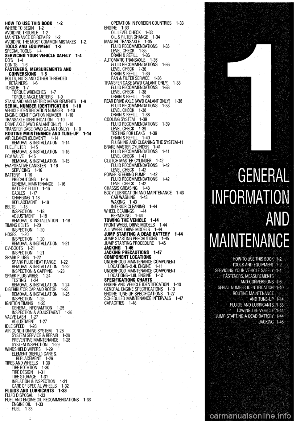
HOW TO USE THIS BOOK 1-2
WHERE TOBEGIN l-2
AVOIDINGTROUBLE 1-2
MAINTENANCEORREPAIR? 1-2
AVOIDINGTHEMOSTCOMMONMISTAKES l-2
TOOLS AND EQUIPMENT 1-2
SPECIALTOOLS l-4
YOUR VEHICLE SAFELY 1-4
DON'TS l-6
FASTENERS, MEASUREMENTS AND
CONVERSIONS l-6
BOLTS,NUTSANDOTHERTHREADED
RETAINERS 1-6
TORQUE l-7
TORQUEWRENCHES l-7
TORQUEANGLEMETERS 1-9
STANDARDANDMETRIC MEASUREMENTS l-9
SERIAL NUMBER IDENTIFICATION l-10
VEHICLE IDENTIFICATION NUMBER l-10
ENGINE IDENTIFICATION NUMBER I-10
TRANSAXLEIDENTIFICATION I-10
DRlVEAXLE(AWDGALANTONLY) l-10
TRANSFERCASE(AWDGALANTONLY) l-10
ROUTINE MAINTENANCE AND TUNE-UP l-14
AIRCLEANER(ELEMENT) 1-14
REMOVAL&INSTALLATION 1-14
FUELFILTER 1-15
REMOVAL &INSTALLATION l-15
PCVVALVE l-15
REMOVAL&INSTALLATION l-15
EVAPORATIVECANISTER l-16
SERVICING 1-16
BATTERY 1-16
PRECAUTIONS I-16
GENERALMAINTENANCE 1-16
BEL BATTERYFLUID 1-16
CABLES I-17
CHARGING I-18
REPLACEMENT 1-18
TS 1-18
INSPECTiON l-18
ADJUSTMENT 1-18
REMOVAL&INSTALLATION 1-18
TIMINGBELTS l-20
INSPECTION l-20
HOSES I-20
INSPECTION l-20
REMOVAL&INSTALLATION
CV-BOOTS 1-21
INSPECTION l-21
SPARKPLUGS l-22
SPARKPLUGHEATRANGE
REMOVAL&INSTALLATION
INSPECTION &GAPPING 1.
SPARKPLUG WIRES 1-24
TESTING 1-24
REMOVAL&INSTALLATION
DISTRIBUTORCAPANDROTOR
REMOVAL&INSTALLATION
INSPECTION 1-25
IGNITIONTIMING 1-25
. GENERALINFORAMTION l-
lNSPECTlON&ADJUSTMENl
VALVE LASH l-27
ADJUSTMENT l-27
IDLESPEED 1-28 1-21
l-22
l-22
-23
1-24
l-25
l-25
.25
1-26
AIR CONDITIONING SYSTEM 1-28
SYSTEMSERVlCEiiREPAlR l-28
PREVENTIVEMAINTENANCE 1-28
SYSTEM INSPECTION l-29
WINDSHIELD WIPERS l-29
ELEMENT(REFILL)CARE&
REPLACEMENT l-29
TIRESANDWHEELS l-30
TIRE ROTATION I-30
TIRE DESIGN 1-31
TIRESTORAGE l-31
INFLATION &INSPECTION l-31
CARE OFSPECIALWHEELS l-32 OPERATION INFOREIGNCOUNTRIES l-33
ENGINE l-33
OILLEVELCHECK 1-33
OIL& FILTER CHANGE l-34
MANUALTRANSAXLE l-35
FLUIDRECOMMENDATIONS l-35
LEVELCHECK l-35
DRAIN&REFILL l-36
AUTOMATICTRANSAXLE l-36
FLUIDRECOMMENDATIONS l-36
LEVELCHECK 1-36
DRAIN&REFILL l-36
PAN & FILTERSERVICE 1-36
TRANSFERCASE(AWDGAlANT ONLY) l-38
FLUIDRECOMMENDATIONS l-38
LEVELCHECK l-38
DRAIN&REFILL l-38
REARDRlVEAXLE(AWDGALANTONLY) l-38
FLUIDRECOMMENDATIONS l-38
LEVELCHECK l-38
DRAIN&REFILL l-38
COOLINGSYSTEM l-39
FLUIDRECOMMENDATIONS l-39
iM-41
FLUIDS AND LUBRICANTS 1-33
FLUID DISPOSAL 1-33
FlJELANDENGlNEOILRECOMMENDATlONS
ENGINE OIL l-33
FUEL l-33
Page 3 of 408
GENERALINFORMATIONAND MAINTENANCE l-3
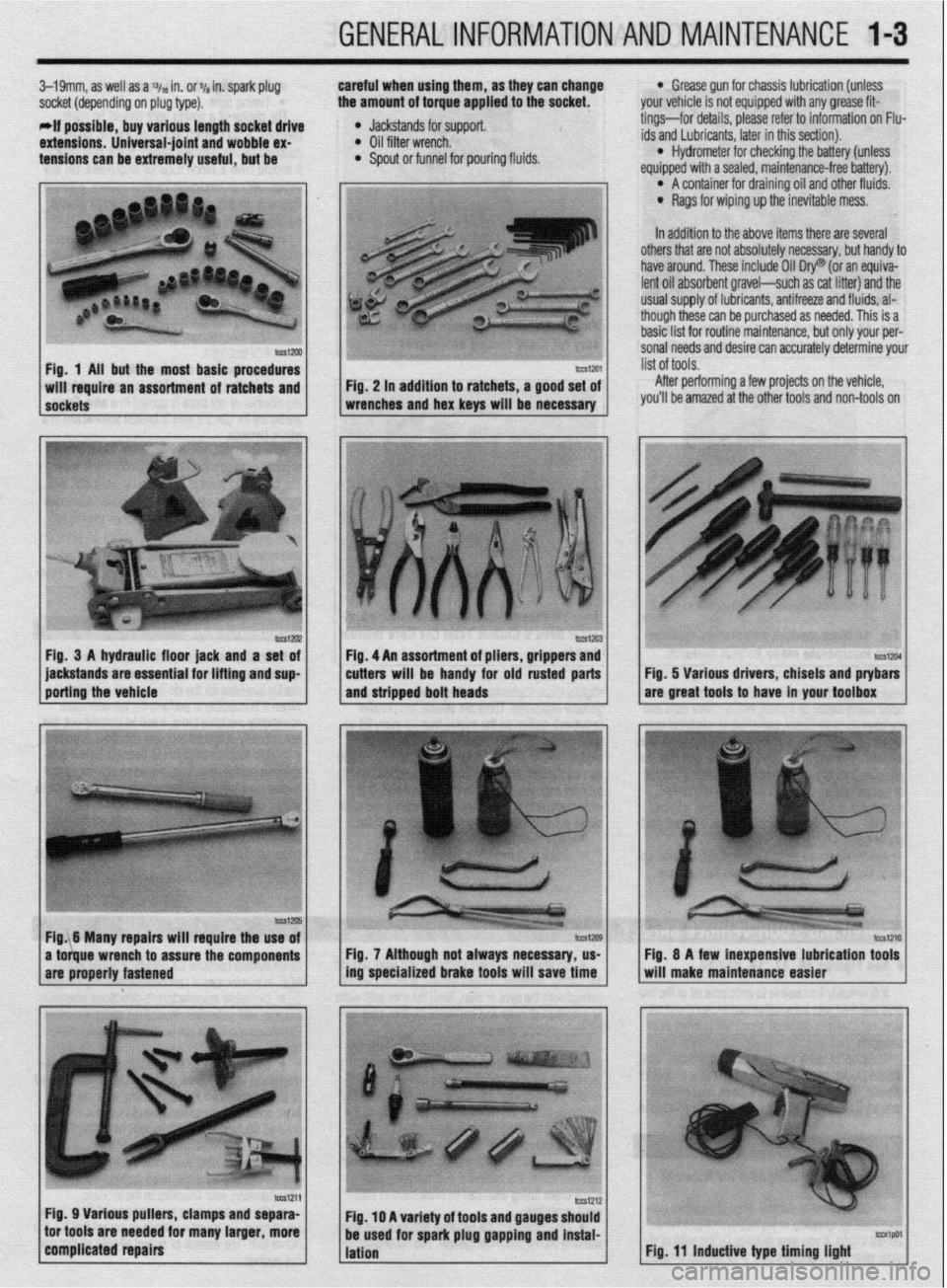
3-19mm, as well as a % in. or ~/a in. spark plug careful when using them, as they can change
socket (depending on plug type). the amount of torque applied to the socket.
-if possible, buy various length socket drive
l Jackstands for support.
extensions. Universal-joint and wobble ex- l Oil filter wrench.
tensions can be extremely useful, but be l Spout or funnel for pouring fluids.
l Grease gun for chassis lubrication (unless
your vehicle is not equipped with any grease fit-
tings-for details, please refer to information on Flu-
ids and Lubricants, later in this section).
l Hydrometer for checking the battery (unless
equiooed with a sealed, maintenance-free batten/).
In addition to the above items there are several O’ A container for draining oil and other fluids.
l Rags for wiping up the inevitable mess.
pi 1 others that are not absolutely necessary, but handy to
have around. These include Oil Dry@ (or an equiva-
lent oil absorbent gravel-such as cat litter) and the
usual SUDDIV of lubricants. antifreeze and fluids. al-
though the.& can be purchased as needed. This is a
basic list for routine maintenance, but only your per-
sonal needs and desire can accurately determine your
Fig. 1 Ail but the most basic procedures
After performing a few projects on the vehicle,
you’ll be amazed at the other tools and non-tools on
lWSl2U2 Fig, 3 A hydraulic floor jack and a set of
jackstands are essential for lifting and sup
porting the vehicle tm1204 Fig. 5 Various drivers, chisels and ptybars
are great tools to have in your toolbox
Fig. 7 Although not always necessary, us-
ing specialized brake tools will save time
Fig. 11 inductive type timing light
Page 20 of 408
GENERALINFORMATIONAND MAINTENANCE l-21
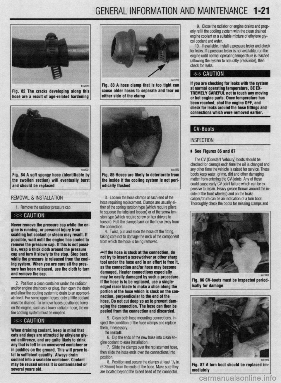
IWSIZXJ FM. 83 A hose clamn that is taa tiaht can
Fig. 82 The cracks developing along this
hose are a result of age-related hardening caise older hoses td separate and ‘iear on
either side of the clamp
lCCS1221 Fig. 84 A soft spongy hose (identifiable by
1 the swollen section) will eventually burst
and should be replaced
IEMOVAL &,INSTALLATION '
1. Remove the radiator pressure cap. her of the sorina tension tvoe (which reouire oliers
3 squeeze the 6bs and loosenj or of the’screw ten-
ion type (which require screw or hex drivers to
oosen). Pull the clamps back on the hose away from
he connection. Never remove the pressure cap while the en-
gine is running, or personal injury from
scalding hot coolant or steam may result. If
possible, wait until the engine has cooled to
remove the pressure cap. If this is not possi-
ble, wrap a thick cloth around the pressure
cap and turn it slowly to the stop. Step back
while the pressure is released from the cool-
ing system. When you are sure all the pres-
sure has been released, use the cloth to turn
and remove the cao.
2. Position a clean container under the radiator
and/or engine draincock or plug, then open the drain
and allow the cooling system to drain to an appropri-
ate level. For some upper hoses, only a little coolant
must be drained. To remove hoses positioned lower
on the engine, such as a lower radiator hose, the en-
tire cooling system must be emptied.
When draining coolant, keep in mind that
cats and dogs are attracted by ethylene gly-
col antifreeze, and are quite likely to drink
any that is left in an uncovered container or
in puddles on the ground. This will prove fa-
tal in sufficient quantity. Always drain
coolant into a sealable container. Coolant
may be reused unless it is contaminated or
several years old. 9. Close the radiator or engine drains and prop-
erly refill the cooling system with the clean drained
engine coolant or a suitable mixture of ethylene gly-
cot coolant and water.
10. If available, install a pressure tester and check
for leaks. If a pressure tester is not available, run the
engine until normal operating temperature is reached
(allowing the system to naturally pressurize), then
check for leaks.
If you are checking for leaks with the system
at normal operating temperature, BE EX-
TREMELY CAREFUL not to touch any moving
or hot engine parts. Once temperature has
been reached. shut the enaine OFF. and
Fig. 85 Hoses are likely to deteriorate from
the inside if the cooling system is not peri-
odically flushed check for leaks around the-hose fittings and
connections which were removed earlier.
INSPECTION
b See Figures 88 and 87
The CV (Constant Velocity) boots should be
checked for damage each time the oil is changed and
any other time the vehicle is raised for service. These
boots keep water, grime, dirt and other damaging
matter from entering the CV-joints. Any of these
could cause early CV-joint failure which can be ex-
pensive to repair. Heavy grease thrown around the in-
side of the front wheel(s) and on the brake
caliper/drum can be an indication of a torn boot.
Thorouahlv check the boots for missina clamos and 3. Loosen the hose clamps at each end of the
rose requiring replacement. Clamps are usually ei-
4. Twist, pull and slide the hose off the fitting,
sking care not to damage the neck of the component
rom which the hose is being removed.
*If the hose is stuck at the connection, do
lot try to insert a screwdriver or other sharp
ool under the hose end in an eff art to free it,
IS the connection and/or hose may become
lamaged. Heater connections especially
nay be easily damaged by such a procedure.
f the hose is to be replaced, use a single-
!dged razor blade to make a slice along the
lortion of the hose which is stuck on the con-
section, perpendicular to the end of the
lose. 00 not cut deep so as to prevent dam-
aging the connection. The hose can then be
keeled from the connection and discarded. Fig. 86 CV-boots must be inspected period-
5.. Clean both hose mounting connections. In-
,pect the condition of the hose clamps and replace
hem, if necessary.
To install:
6. Dip the ends of the new hose into clean en-
fine coolant to ease installation.
7. Slide the clamps over the replacement hose,
hen slide the hose ends over the connections into
rosition.
8. Position and secure the clamps at least l/d in.
6.35mm) from the ends of the hose. Make sure they
Ire located beyond the raised bead of the connector.
Page 21 of 408
l-22 GENERALINFORMATIONAND MAINTENANCE
tears. If the boot is damaged, it should be replaced
trode is to the block’s cooling passages) the cooler it
your driving is long distance, high speed travel, use a
immediately. Please refer to Section 7 for procedures.
will operate. A plug that absorbs little heat and re-
colder plug; if most of your driving is stop and go,
mains too cool will quickly accumulate deposits of
use a hotter plug. Original equipment plugs are gen-
oil and carbon since it is not hot enough to burn
erally a good compromise between the 2 styles and
them off. This leads to plug fouling and consequently
most people never have the need to change their
to misfiring. A plug that absorbs too much heat will
plugs from the factory-recommended heat range.
ti See Figure 88 have no deposits but, due to the excessive heat, the
,electrodes will burn away quickly and might possibly
REMOVAL &INSTALLATION
A typical spark plug consists of a metal shell sur- lead to preignition or other ignition problems. Preig-
rounding a ceramic insulator. A metal electrode ex- nition takes place when plug tips get so hot that they
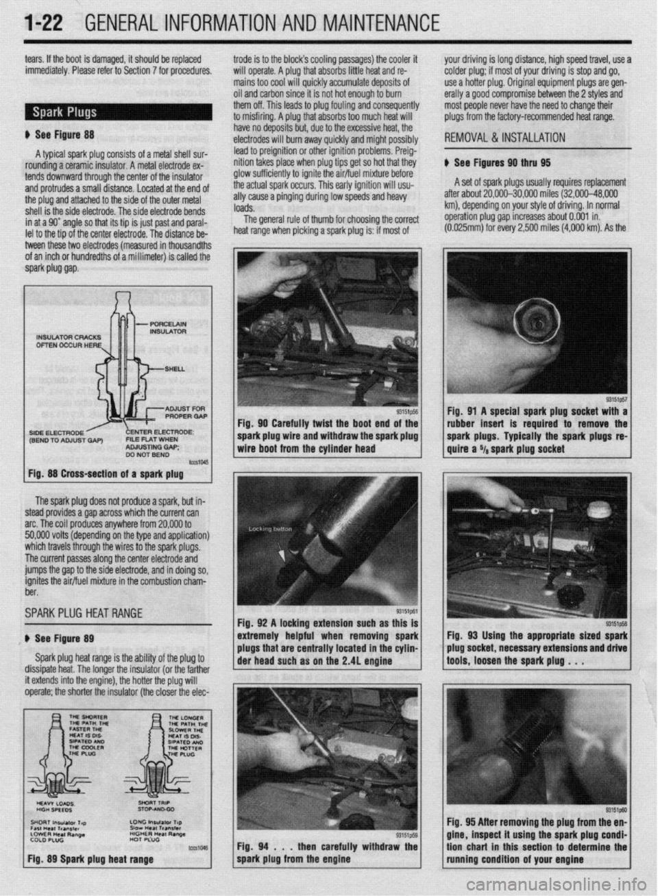
ti See Figures 90 thru 95
tends downward through the center of the insulator glow sufficiently to ignite the air/fuel mixture before
and protrudes a small distance. Located at the end of the actual spark occurs. This early ignition will usu- A set of spark plugs usually requires replacement
the plug and attached to the side of the outer metal ally cause a pinging during low speeds and heavy after about 20,000-30,000 miles (32,000-48,000
shell is the side electrode. The side electrode bends loads. km), depending on your style of driving. In normal
in at a 90” angle so that its tip is just past and paral- The general rule of thumb for choosing the correct operation plug gap increases about 0.001 in.
lel to the tio of the center electrode. The distance be- heat range when picking a spark plug is: if most of (0.025mrn) for every 2,500 miles
(4,000 km). As the
tween these two electrodes (measured in thousandths
of an inch or hundredths of a millimeter) is called the
spark piug gap.
The spark plug does not produce a spark, but in-
steed provides a gap across which the current can
arc. The coil produces anywhere from 20,000 to
50,000 volts (depending on the type and application)
which travels through the wires to the spark plugs.
The current passes along the center electrode and
jumps the gap to the side electrode, and in doing so,
ignites the air/fuel mixture in the combustion charn-
ber.
SPARKPLUG HEATRANGE
ti See Figure 89
Spark plug heat range is the ability of the plug to
dissipate heat. The longer the insulator (or the farther
INSULATOR CRACKS
OFTEN OCCUR HERE
SIDE ELECTRODE ENTER ELECTRODE:
(SEND TO ADJUST GAP) FILE FLAT WHEN
ADJUSTING GAP;
DO NOT BEND
Fig. 88 Cross-section of a spark plug
it extends into the engine), the hotter the plug will
operate; the shorter the insulator (the closer the elec- Fig. 90 Carefully twist the boot end of the
I
spark plug wire and withdraw the spark plug
wire boot from the cylinder head
Fig. 92 A locking extension such as this is
extremely helpful when removing spark
plugs that are centrally located in the cyhn-
Fig. 94 . . .
then carefully withdraw the
spark plug from the engine Fig. 91 A special spark plug socket with a
rubber insert is required to remove the
spark plugs. Typically the spark plugs
re-
quire a Ya spark plug socket
Fig, 93 Using the appropriate sized spark
plug socket, necessary extensions and drive
tools, loosen the spark plug . . .
93151ptxl Fig. 95 After removing the plug from the en-
gine, inspect it using the spark plug condi-
tion chart in this section to determine the
running condition of your engine
Page 32 of 408
GENERALINFORMATIONAND MAINTENANC-E 1133
Used fluids such as engine oil, transaxle fluid, an-
tifreeze and brake fluid are hazardous wastes and
must be disposed of properly. Before draining any
fluids, consult with your local authorities; in many ar-
eas, waste oil, antifreeze, etc. is being accepted as a
part of recycling programs. A number of service sta-
tions and auto parts stores are also accepting waste
fluids for recycling.
Be sure of the recycling center’s policies before
draining any fluids, as many will not accept different
fluids that have been mixed together.
ENGINE OIL
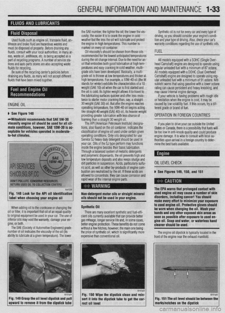
6 See Figure 148
WMitsubishi recommends that SAE 5W-30
viscosity engine oil should be used for all clia
mate conditions, however, SAE low-30 is ac
ceptable for vehicles operated in moderate-
to-hot climates. the SAE number, the lighter the oil; the lower the vis-
cosity, the easier it is to crank the engine in cold
weather but the less the oil will lubricate and protect
the engine in high temperatures. This number is
marked on every oil container.
Oil viscosity’s should be chosen from those oils
recommended for the lowest anticipated temperatures
during the oil change interval. Due to the need for an
oil that embodies both good lubrication at high tem-
peratures and easy cranking in cold weather, multi-
grade oils have been developed. Basically, a multi-
grade oil is thinner at low temperatures and thicker at
high temperatures. For example, a low-40 oil (the W
stands for winter) exhibits the characteristics of a 10
weight (SAE 10) oil when the car is first started and
the oil is cold. Its lighter weight allows it to travel to
the lubricating surfaces quicker and offer less resis-
tance to starter motor cranking than, say, a straight
30 weight (SAE 30) oil. But atier the ensine reaches
operating temperature, the low-40 oil begins acting
like straight 40 weight (SAE 40) oil, its heavier weight
providing greater lubrication with less chance of
foaming than a straight 30 weight oil. Synthetic oil is not for every car and every type of
driving, so you should consider your engine’s condi-
tion and your type of driving. Also, check your car’s
warranty conditions regarding the use of synthetic oils.
FUEL
All models equipped with a SOHC (Single Over-
head Camshaft) engine are designed to operate using
regular unleaded fuel with a minimum of 87 octane.
All models equipped with a DOHC (Dual Overhead
Camshaft) engine are designed to operate using reg-
ular unleaded fuel with a minimum of 91 octane. Mit-
subishi warns that using gasoline with a lower octane
rating can cause persistent and heavy knocking, and
may cause internal engine damage.
If your vehicle is having problems with rough idle
or hesitation when the enoine is cold, it mav be
caused by low volatility fuel. If this occurs, iry a dif-
ferent grade or brand of fuel.
'OPERATION 1~ FOREIGN COUNTRIES
lccS1235 Fig. 148 look for the API oil identification
Non-detergent motor oils or straight mineral
label when choosing your enaine oil oils should not be used in your engine.
When adding oil to the crankcase or changing the
0 Nil or filter, it is important that oil of an equal quality
I original equipment be used in your car. The use of
. tc mtenor 011s may void the warranty, damage your en-
gine, or both. __
The SAE (Society of Automotive Engineers) grade
number of oil indicates the viscosity of the oil (its
ability to lubricate at a given temperature). The lower
Fig. 149 Grasp the oil level dipstick and pull
upward to remove it from the dipstick
tube
The API (American Petroleum Institute) designa-
tions, also found on the oil container, indicates the
classification of engine oil used under certain given
operating conditions. Only oils designated for use
Service SJ heavy duty detergent should be used in
your car. Oils of the SJ type perform may functions If you plan to drive your car outside the United
States or Canada, there is a possibility that fuels will
be too low in anti-knock quality and could produce
engine damage. It is wise to consult with local au-
thorities upon arrival in a foreign country to deter-
mine the best fuels available.
inside the engine besides their basic lubrication.
Through a balanced system of metallic detergents
and polymeric dispersants, the oil prevents high and
low temperature deposits and also keeps sludge and
dirt particles in suspension. Acids, particularly sulfu-
OILLEVELCHECK ric acid, as well as other by-products of engine com-
bustion are neutralized by the oil. If these acids are
# See Figures 149, 150, and 151
allowed to concentrate, thev can cause corrosion and
rapid wear of the internal engine parts.
Synthetic Oil
There are many excellent synthetic and fuel-effi-
cient oils currently available that can provide better
gas mileage, longer service life and, in some cases,
better engine protection. These benefits do not come
without a few hitches, however; the main one being
the price of synthetic oil, which is significantly more
expensive than conventional oil.
.
The EPA warns that urolonoed contact with used engine oil ma; cause-a number of skin
disorders, including cancer! You should
make every effort to minimize your exposure
to
used engine oil. Protective gloves should
be worn when changing the oil. Wash your
hands and any other exposed skin areas as
soon as possible after exposure to used en-
gine oil. Soap and water, or waterless hand
cleaner should be used.
Fig. 150 Wipe the dipstick clean and rein-
sert it into the dipstick
tube to get the cor-
rect oil level The engine oil dipstick is typically located in the
Fig. 151 The oil level should be between the
marks/notches on the dipstick
Page 33 of 408
.
l-34 GENERALINFORMATIONAND MAINTENANCE
Engine oil level should be checked every time you
put fuel in the vehicle or are under the hood perform- miles of highway driving. Fluid which is warmed to
normal operating temperature will flow faster, drain
ing other maintenance.
1. Park the vehicle on a level surface.
2. The enaine mav be either hot or cold when
, if it is hot, wait a few min- checking oil level. The EPA warns that prolonged contact with
used engine oil may cause a num’ * * *
dianrAnrr inrldinn ranrnrl V#lll more completely and remove more contaminants
frnm tho clnnine
utes after the engine has been turned OFF to allow the
oil to drain back into the crankcase. If the engine is
cold, do not start it before checking the oil level. point on the oil pan. If not, you may have to raise the
vehicle slightly higher on one jackstand (side) than
3. Open the hood and locate the engine oil dip-
stick. Pull the dipstick from its tube, wipe it clean,
and reinsert it. Make sure the diDstick is fullv in-
serted.
4. Pull the dipstick from its tube again. Holding it to used engin
be worn whet
handsandan
so*m ..#a . . . . .
IDer 01 SKlll u,yu,u=,+, ,,,u,uu,,,u uu,,u=, i , vu should
uff art to minimize your exposure
le oil. Protective gloves should
1 changing the oil. Wash your
y other exposed skin areas as
111 aJ vv4ble after exposure to used en-
m nil St-mn mwl w&or nr umtarlncr hand gin Y “II. ““up “ll” .,U.“I, “rn W.Y.“. .““I .I....” cleaner should be used.
horizontally, read the oil level. The oilshould be be-
tween the MIN and MAX marks or the notches on the
dipstick. If the oil is below the MIN mark or lower
notch, add oil of the proper viscosity through the
capped opening of the valve cover. *The engine oil and oil filter should be
changed at the recommended intervals on
the Maintenance Chart. Though some manu-
facturers have at times recommended chang-
ing the filter only at every other oil change, ’
Chilton recommends that you always change
ll”,,, Cl>” ““y”‘“. 1. Raise and support the vehicle safely on jack-
stands. Make sure the oil drain olua is at the lowest
the other.
2. Before you crawl under the vehicle, take a look
at where you will be working and gather all the nec-
essary tools, such as a few wrenches or a ratchet and
strip of sockets, the drain pan, some clean rags and,
if the oil filter is more accessible from underneath the
vehicle, you will also want to grab a bottle of oil, the
new filter and a filter wrench at this time.
5. Reolace the diostick. and check the level aaain
. The benefit of fresh oil
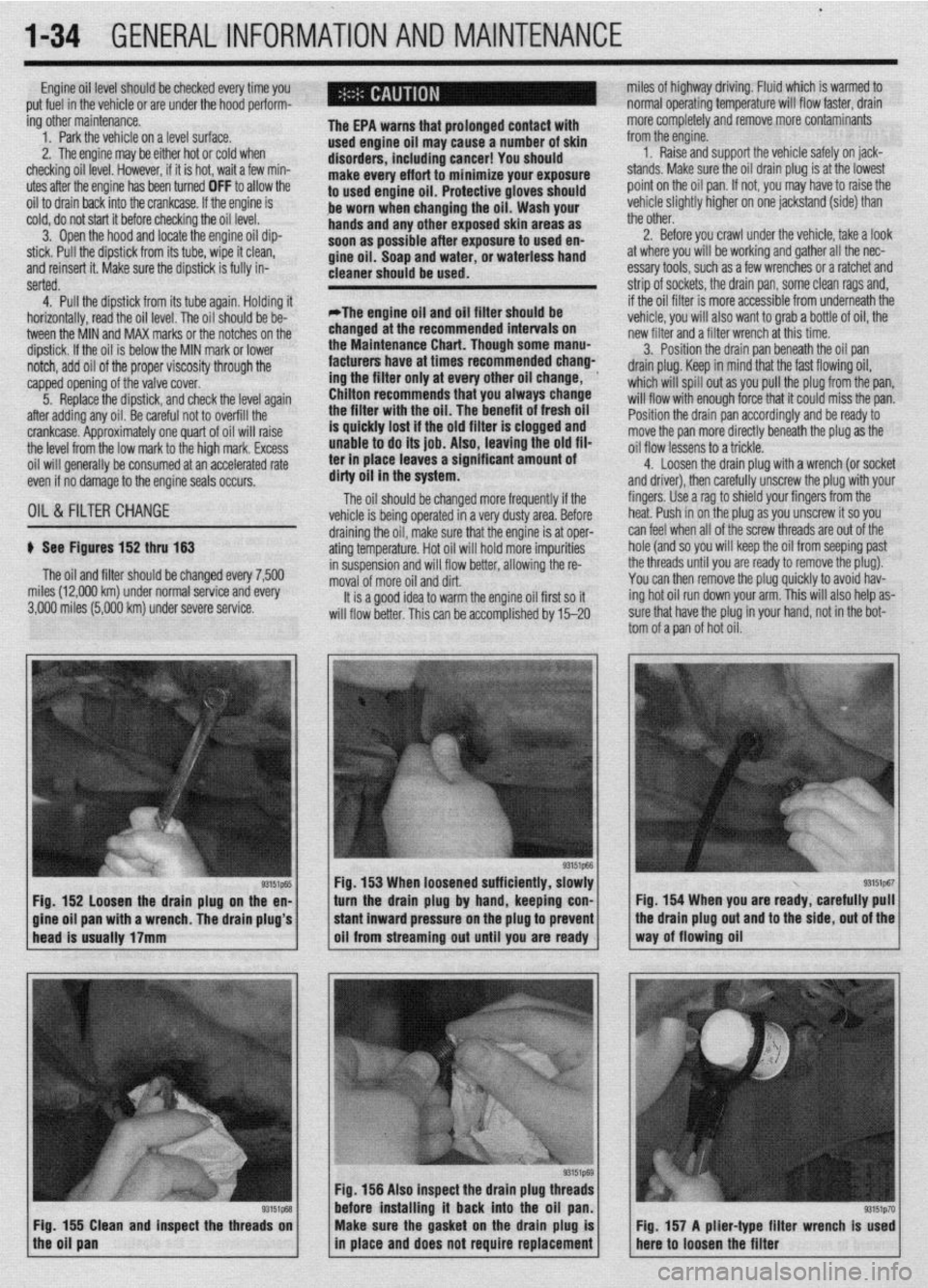
p See Figures 152 thru 153
The oil and filter should be changed every 7,500
miles (12,000 km) under normal service and every
3,000 miles (5,000 km) under severe service.
93151p-55 Fig. 152 loosen the drain plug on the en-
a wrench. The drain plug’s 3. Position the drain pan beneath the oil pan
drain plug. Keep in mind that the fast flowing oil,
which will spill out as you pull the plug from the pan,
will flow with enough force that it could miss the pan.
Position the drain pan accordingly and be ready to
move the pan more directly beneath the plug as the
oil flow lessens to a trickle.
4. Loosen the drain ~lua with a wrench (or socket
and driver), then carefuliy unscrew the plug with your
fingers. Use a rag to shield your fingers from the
heat. Push in on the plug as you unscrew it so you
draining the oil, make sure that the engine is at oper- can feel when all of the screw threads are out of the
ating temperature. Hot oil will hold more impurities hole (and so you will keep the oil from seeping past
in suspension and will flow better, allowing the re- the threads until you are ready to remove the plug).
moval of more oil and dirt. You can then remove the plug quickly to avoid hav-
It is a good idea to warm the engine oil first so it ing hot oil run down your arm. This will also help as-
will flow better. This can be accomolished bv 15-20 sure that have the plug in your hand, not in the bot-
tom of a pan of hot oil.
Fig. 153 When loosened sufficiently, slowly
turn the drain plug by hand, keeping con- Fig. 154 When you are ready, carefully pull
Fig. 156 Also inspect the drain plug th
before installing it back into the oil
Fig. 155 Clean and inspect the threads on
the oil pan Make sure the gasket on the drain plug is
in place and does not require replacement Fig. 157 A plier-type filter wrench Is used
here to loosen the filter
Page 35 of 408
.
l-36 GENERALINFORMATIONAND MAINTENANCE
Install the drain plug and tighten to 22 ft. Ibs.
(304Nm)
5. Refill the transaxle to the proper level, as
shown in the Capacities chart, with the appropriate
fluid. The oil level should be at the bottom of the oil
filler hole. I
6. When the oil reaches the orooer level, install
the filler plug and tighten to 22 ft. Ibs. (30 Nm).
FLUID RECOMMENDATIONS
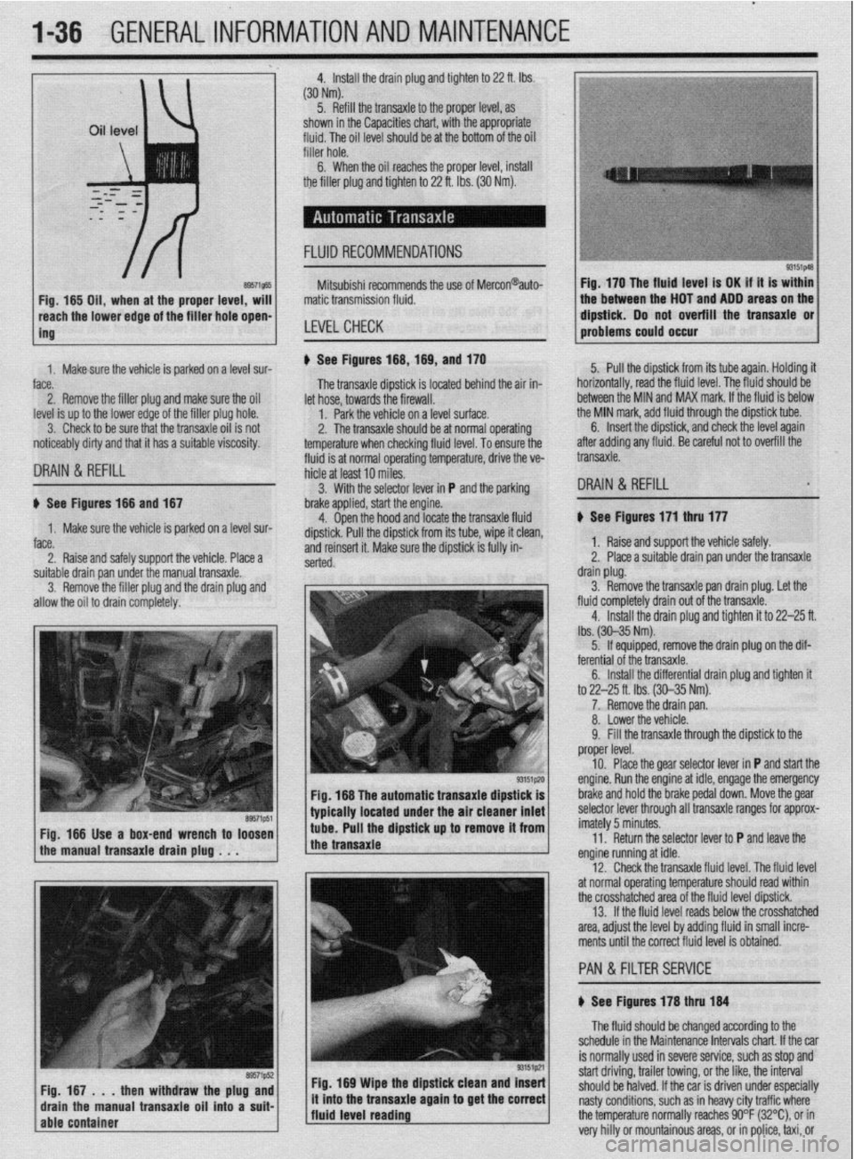
8957i565 Fig, 165 Oil, when at the proper level, will
reach the lower edge of tC=+ frfr*r u*rn -non-
ing Mitsubishi recommends the use of Mercon@auto-
matic transmission fluid.
LEVELCHECK
Fig. 170 The fluid level is OK if it is within
the between the HOT and ADD areas on the
&&i& Do not overfill the transaxle or
-.*".."... -- .*"- problems could o ccur
1. Makesure the vehicle is oarked on a level sur-
face.
2. Remove the filler plug and make sure the oil
level is up to the lower edge of the filler plug hole.
3. Check to be sure that the transaxle oil is not
noticeably dirty and that it has a suitable viscosity. u See Figures 168,169, and 170
fluid is at normal operating temperature, drive the ve- The transaxle dipstick is located behind the air in-
hicle at least 10 miles. let hose, towards the firewall.
1. Park the vehicle on a level surface.
2. The transaxle should be at normal operating
temperature when checking fluid level. To ensure the 5. Pull the dipstick from its tube again. Holding it
horizontally, road the fluid level. The fkrid should be
between the MIN and MAX mark. If the fluid is below
the MIN mark, add fluid through the dipstick tube.
DRAIN & REFILL
6. Insert the dipstick, and check the level again
after adding any fluid. Be careful not to overfill the
transaxle.
3. With the selector lever in P and the parking
DRAIN & REFILL u See Figures 166 and 167
1. Make sure the vehicle is parked on a level sur-
face.
2. Raise and safely support the vehicle. Place a brake applied, start the engine.
4. Open the hood and locate the transaxle fluid
dipstick. Pull the dipstick from its tube, wipe it clean,
and reinsert it. Make sure the dipstick is fully in-
serted.
suitable drain pan under the manual transaxle.
3. Remove the filler plug and the drain plug and
allow the oil to drain completely.
Fig. 166 The automatic transaxle dipstick is
typically located under the air cleaner inlet
Fig. 166 Use a box-end wrench to loosen
the manual transaxle drain plug . . . tube. Pull the dipstick up to remove it from
the transaxle
Fig. 169 Wipe the dipstick clean and Insert
/fluid level reading ., it mto the transaxle agam to get the correct
j The fluid should be changed according to the
schedule in the Maintenance Intervals chart. If the car
is normally used in severe service, such as stop and
start driving, trailer towing, or the like, the interval
should be halved. If the car is driven under especially
nasty conditions, such as in heavy city traffic where
the temperature normally reaches 90°F (32%), or in
very hilly or mountainous areas, or in police, taxi, or b See Figures 171 thru 177
1. Raise and support the vehicle safely.
2. Place a suitable drain pan under the transaxle
drain plug.
3. Remove the transaxle pan drain plug. Let the
fluid completely drain out of the transaxle.
4. Install the drain plug and tighten it to 22-25 ft.
lbs. (30-35 Nm).
5. If equipped, remove the drain plug on the dif-
ferential of the transaxle.
6. Install the differential drain plug and tighten ft
to 22-25 ft. Ibs. (30-35 Nm).
7. Remove the drain pan.
8. Lower the vehicle.
9. Fill the transaxle through the dipstick to the
proper level.
10. Place the gear selector lever in P and start the
engine. Run the engine at idle, engage the emergency
brake and hold the brake pedal down. Move the gear
selector lever through all transaxle ranges for approx-
imately 5 minutes.
11. Return the selector lever to P and leave the
engine running at idle.
12. Check the transaxle fluid level. The fluid level
at normal operating temperature should read within
the crosshatched area of the fluid level dipstick.
13. If the fluid level reads below the crosshatched
area, adjust the level by adding fluid in small incre-
ments until the correct fluid level is obtained.
PAN &FILTER SERVICE
b See Figures 178 thru 184
Page 37 of 408
t
1-38 GENERALINFORMATIONAND MAINTENANCE
11 I Add the recommended automatic transaxle
fluid to the transaxle through the dipstick tube. You
will need a long necked funnel, or a funnel and tube
to do this. A quick check of the capacities chart later
in this Section will reveal the capacity of the transaxle
in your vehicle. On a first fill after removing the pan
and filter, this number should be cut into a ‘hand
checked on the dipstick before refilling.
12. With the transaxle in P, put on the parking
brake, block the front wheels, start the engine and let
it idle. DO NOT RACE THE ENGINE. DO NOT MOVE
THE LEVER THROUGH ITS RANGES.
13. With the lever in Park, check the fluid level. If
it’s OK, take the car out for a short drive, park on a
level surface, and check the level again, as outlined
earlier in this section. Add more fluid if necessary. Be
careful not to overfill, which will cause foaming and
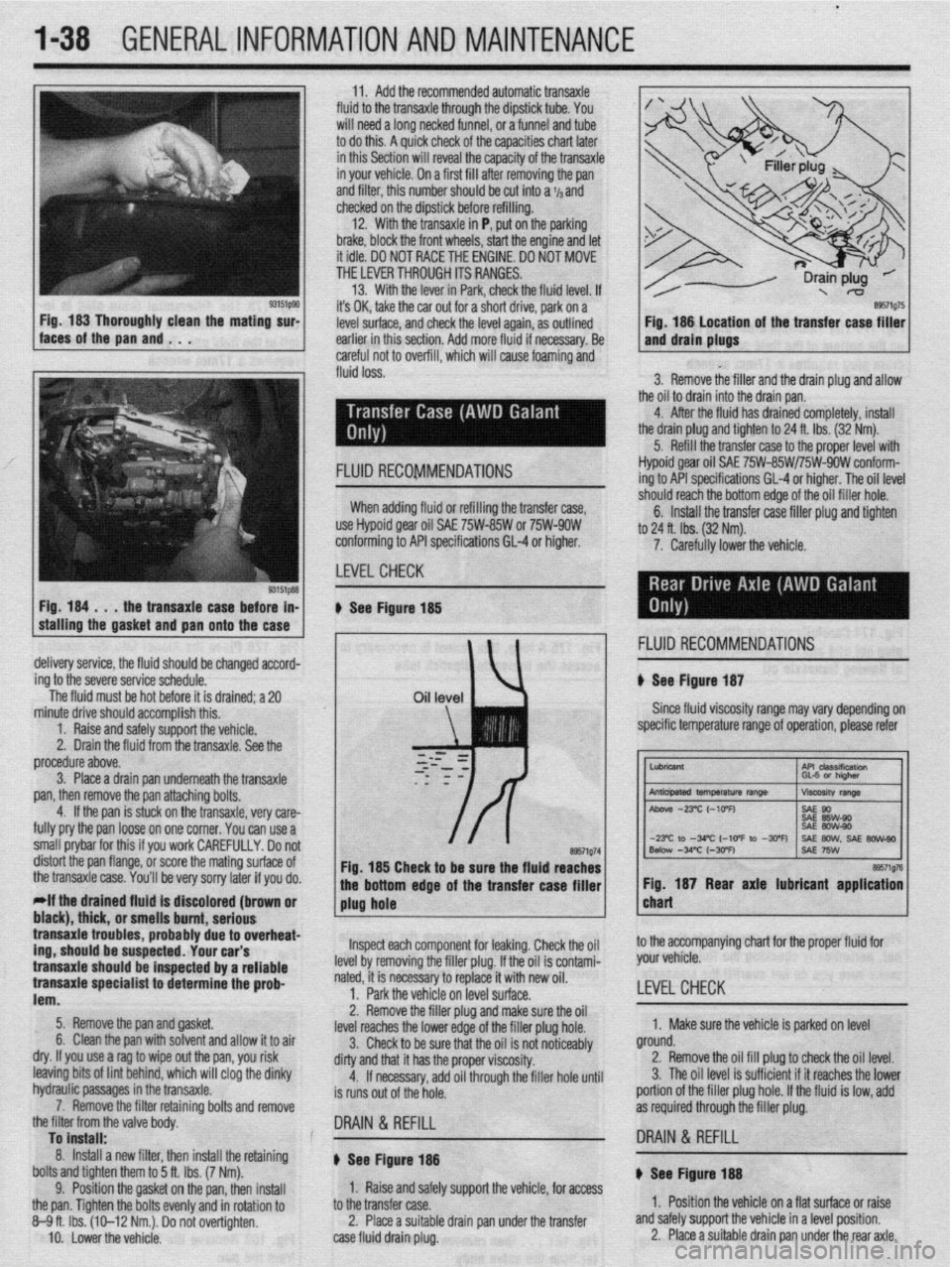
w fluid loss. n of the transfer case filler
3. Remove the filler and the drain plug and allow
the oil to drain into the drain pan.
4. After the fluid has drained completely, install
the drain plug and tighten to 24 ft. Ibs. (32 Nm).
5. Refill the transfer case to the proper level with
Fig. 184 . . .
the transaxle case before in-
stalling the gasket
and pan onto the case FLUID RECOMMENDATIONS Hypoid gear oil SAE 75W-85W/75W-9OW conform-
ing to API specifications GL-4 or higher. The oil level
-‘-,*I’ -nnnh +‘* “%om edge of the oil filler hole.
nxfer raw filler nlm and tinhtm When adding fluid or refilling the transfer case,
use Hypoid gear oil SAE 75W-85W or 75W-9OW
conforming to API specifications 61-4 or higher.
LEVELCHECK 6. Install the tra .._._. ____ .._. T.-J _.._ .lJ . .._..
to 24 ft. lbs. (32 Nm).
7. Carefully lower the vehicle.
u See Figure 185
, 1 FLUID RECOMMENDATIONS
delivery service, the fluid should be changed accord-
ing to the severe service schedule.
The fluid must be hot before it is drained; a 20 u See Figure 187
Since fluid viscosity range may
vary depending on
specific temperature range of operation, please refer
~~
tne transaxle case.
You’ll be very sorry later if you do. bottom edge of the transfer case filler 1 1 Fig. 187 Rear axle lubricant application I
*If the drained fluld is discolored (brown or
1 plug hole chart black), thick, or pmmll~ hmmt nnrinmm I transaxle trouble .llln3llU ““III., url,““P s, probably due to overheat-
,r..rr,rA “#.a.- rrdr
trig, should be susp~~lr;u. lvUl vLlr J
transaxle should be inspected by a reliable
transaxle specialist to determine the prob-
lem.
5. Remove the pan and gasket.
6. Clean the pan with solvent and allow it to air
dry. If you use a rag to wipe out the pan, you risk
leaving bits of lint behind, which will clog the dinky
hydraulic passages in the bansaxle.
7. Remove the filter retaining bolts and remove
the filter from the valve bodv. lnsoect each component for leaking. Check the oil
he filler plug. If the oil is contami-
ry to replace it with new oil.
if% nn IPVPI z11rf2r~
level by removing t
nated, it is necessa
1. Park the vehi,., -.. ,-.“, __. ,“-_.
2. Remove the filler plug and make sure the oil
level reaches the lower edge of the filler plug hole.
3. Check to be sure that the oil is not noticeably
dirty and that it has the proper viscosity.
4. If necessary, add oil through the filler hole until
is runs out of the hole. to the accompanying chart for the proper fluid for
your vehicle.
LEVEL CHECK
1. Make sure the vehicle is parked on level
ground.
2. Remove the oil fill plug to check the oil level.
3. The oil level is sufficient if it reaches the lower
portion of the filler plug hole. If the fluid is low, add
as required through the filler plug.
To install: .
8. Install a new filter, then install the retaining
bolts and tighten them to 5 ft. Ibs. (7 Nm).
9. Position the gasket on the pan, then install
the pan. Tighten the bolts evenly and in rotation to
8-9ft. Ibs. (10-12 Nm.). Do not overtighten.
IO. Lower the vehicle. DRAIN & REFILL
I8 DRAIN & REFILL
u See Figure 188 ) See Figure- 14
1. Raise and safely support the vehicle, for access
to the transfer case.
2. Place a suitable drain pan under the transfer
case fluid drain plug. 1. Position the vehicle on a flat surface or raise
and safely support the vehicle in a level position.
2. Place a suitable drain pan under the rear axle.