1900 MITSUBISHI DIAMANTE change key battery
[x] Cancel search: change key batteryPage 54 of 408

ENGINEELECTRICAL 2-7
3. Detach the electrical connectors for the COIL
4. Remove the retaining screws and coil from en-
gine.
5. Installation is the reverse of the removal proce-
dure.
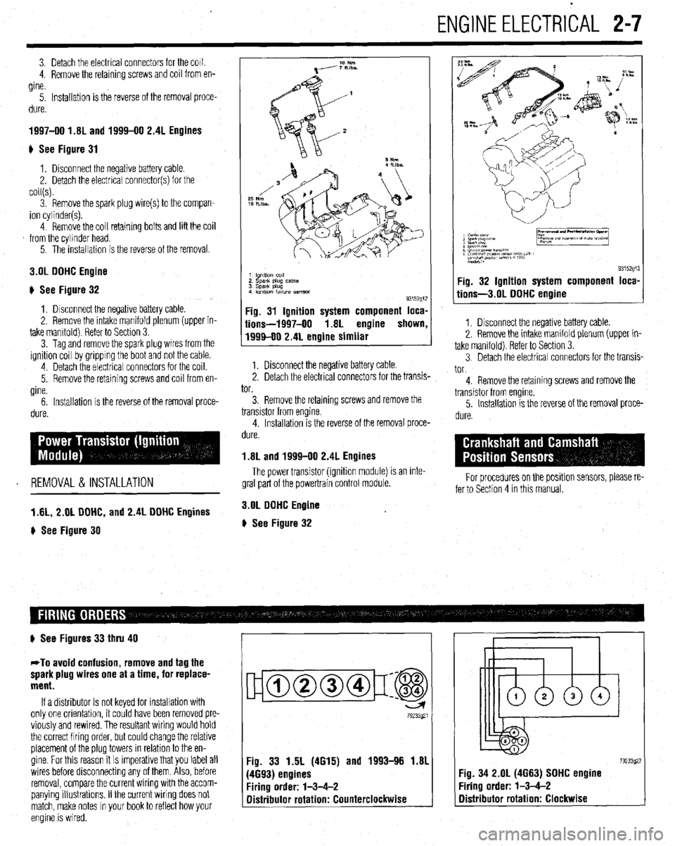
1997-00 1.81 and 1994-00 2.4L Engines
) See Figure 31
1, Disconnect the negative battery cable.
2. Detach the electrical connector(s) for the
coil(s).
3. Remove the spark plug wire(s) to the compan-
ion cylinder(s).
4 Remove the coil retaining bolts and lift the coil
from the cylinder head.
5. The installation is the reverse of the removal.
3.OL DOHC Engine
# See Figure 32
1, Disconnect the negative battery cable.
2. Remove the intake manifold plenum (upper in-
take mamfold) Refer to Section 3.
3. Tag and remove the spark plug wires from the
ignition coil by gripping the boot and not the cable.
4 Detach the electrical connectors for the coil.
5. Remove the retaining screws and coil from en-
gine.
6. Installation is the reverse of the removal proce-
dure.
REMOVAL &INSTALLATION
1 AL, 2.01 DOHC, and 2.4L DOHC Engines
) See Figure 30
1 lgnltlo” co,,
2 sparlt plug case
3 Spark plug
4 Imltlon fatlure semm
93152g1:
Fig. 31 Ignition system component loca,
iions-1997-00 1.8L engine shown
1999-00 2.4L engine similar
1. Disconnect the negative battery cable.
2. Detach the electrical connectors for the transis-
tor.
3. Remove the retaining screws and remove the
transistor from engine.
4. Installation is the reverse of the removal proce-
dure.
1.8L and 1999-00 2.4L Engines
The power transistor (ignition module) is an inte-
gral part of the powertrain control module.
3.OL DOHC Engine
# See Figure 32
9315291 Fig. 32 Ignition system component loca,
tions-3.01 DOHC engine
1. Disconnect the negative battery cable.
2. Remove the intake manifold plenum (upper in-
take manifold). Refer to Section 3.
3 Detach the electrical connectors for the transis-
tor.
4. Remove the retaining screws and remove the
transistor from engine.
5. Installation is the reverse of the removal proce-
dure.
For procedures on the positlon sensors, please re-
fer to Section 4 in this manual.
# See Figures 33 thru 40
*To avoid confusion, remove and tag the
spark plug wires one at a time, for replace-
ment.
If a distributor is not keyed for installation with
only one orientation, it could have been removed pre-
viously and rewired. The resultant wiring would hold
the correct firing order, but could change the relative
placement of the plug towers in relation to the en-
gine. For this reason it is imperative that you label all
wires before disconnecting any of them. Also, before
removal, compare the current wiring with the accom-
panying illustrations. If the current wiring does not
match, make notes in your book to reflect how your
engine is wired.
ujamm-p:@
79233921
Fig. 33 1.5L (4615) and 1993-96 1.81
(4693) engines
Firing order: l-3-4-2
Distributor rotation: Counterclockwise 7923392: :ig. 34 2.OL (4663) SOHC engine
‘iring order: l-3-4-2
Distributor rotation: Clockwise
Page 154 of 408

DRIVEABILITYAND EMISSIONS CONTROLi 4-11
fold. Resistance changes in response to the ambient
air temperature. The sensor has a negative tempera-
ture coefficient. As the temperature of the sensor
rises the resistance across the sensor decreases. Thil
provides a signal to the PCM indicating the tempera-
ture of the incoming air charge. This sensor helps the
PCM to determine spark timing and air/fuel ratio. In-
formation from this sensor is added to the pressure
sensor information to calculate the air mass being
sent to the cylinders. The IAT receives a 5-volt refer-
ence signal and the signal return is based upon the
change in the measured resistance due to tempera-
ture.
TESTING
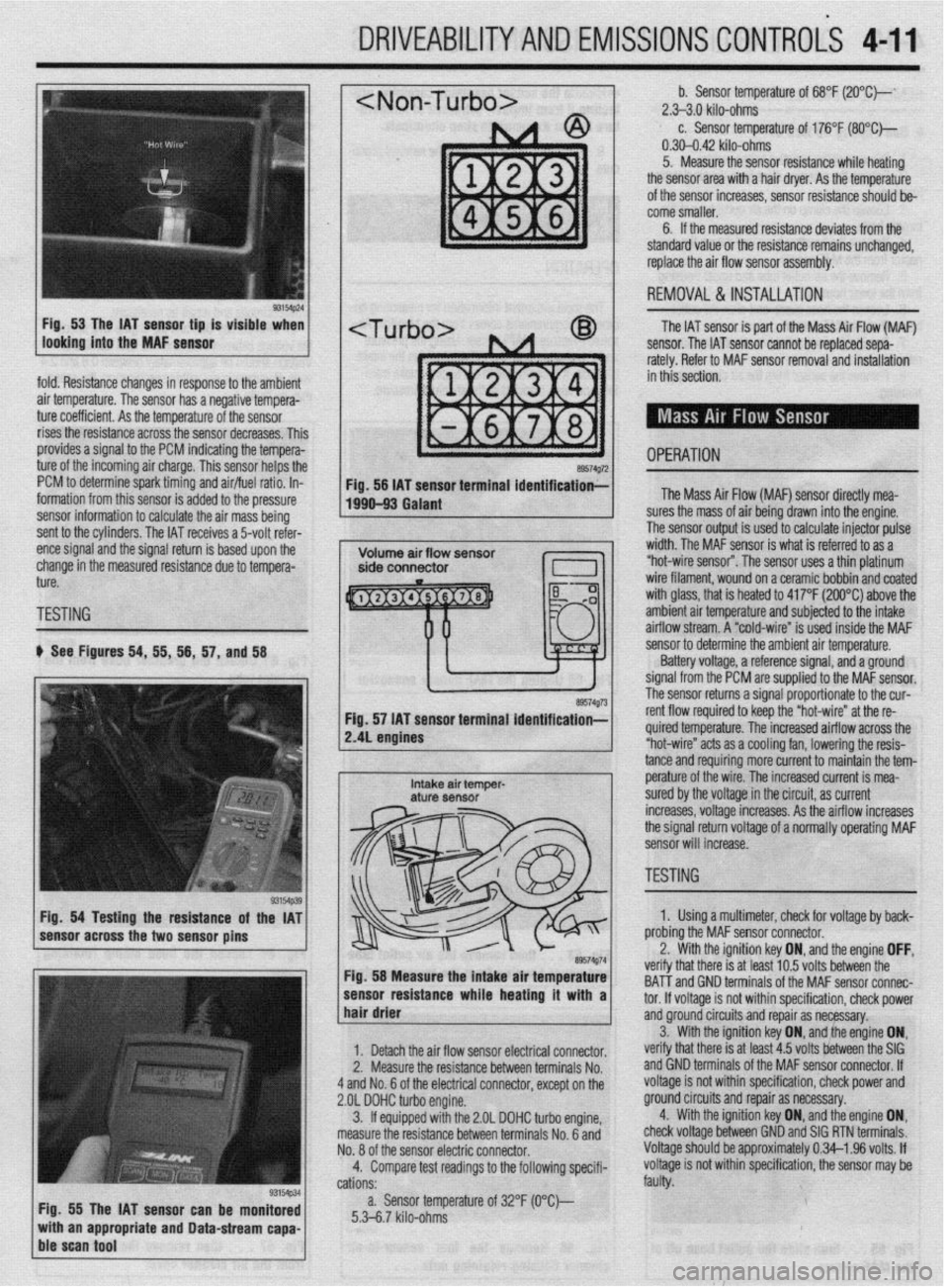
b See Figures 54, 55, 56, 57, and 58
Fig. 54 Testing the resistance of the IAT
sensor across the two sensor pins
Fig. 55 The IAT sensor can be monitored
with an appropriate and Data-stream capa-
ble scan tool
~1 b. Sensor temperature of 68°F (2O”C)--‘ 2.>3.0 kilo-ohms c. Sensor temperature of 176°F (SO*C)-
0.30-0.42 kilo-ohms
5. Measure the sensor resistance while heating
the sensor area with a hair dryer. As the temperature
of the sensor increases, sensor resistance should be-
come smaller.
6. If the measured resistance deviates from the
standard value or the resistance remains unchanged,
replace the air flow sensor assembly.
1 REMOVAL&INSTALLATION
The IAT sensor is part of the Mass Air Flow (MAF)
sensor. The IAT sensor cannot be replaced sepa-
rately. Refer to MAF sensor removal and installation
in this section.
- OPERATION a9574g72 Fig. 56 IAT sensor terminal identification;-
1990-93 Galant The Mass Air Flow (MAF) sensor directly mea-
lres the mass of air being drawn into the engine.
I ?he sensor output is used to calculate injector pulse
width. The MAF sensor is what is referred to as a
“hot-wire sensor”. The sensor uses a thin platinum
wire filament, wound on a ceramic bobbin and coated
with glass, that is heated to 417°F (200°C) above the
amh+en+ nir +PmnPrfijre and subiected to the intake
..I._ ~ ..-.. .“..‘r-,u.. ai mow stream. A “cold-wire” is used inside the MAF
sensor resuirance wnoe nearmg ir wnn a 1
hair drier ‘hat melt: IS al I~“< ,“.., lvllQ UtiLnbtill ,,,=
tnd GND terminals of the MAF sensor connec-
tor. If voltaae is not within specification, check power
1. Detach the air flow sensor electrical connector.
2. Measure the resistance between terminals No.
4 and No. 6 of the electrical connector, except on the
2.OL DOHC turbo engine.
3. ff equipped with the 2.OL DOHC turbo engine,
measure the resistance between terminals No. 6 and
No. 8 of the sensor electric connector.
4. Compare test readings to the following specifi-
cations:
a. Sensor temperature of 32°F (O“C)--
5.3-6.7 kilo-ohms and groundcircuits and repair as necessary.
verify that there is at least 4.5 volts between the SIG 3. With the ignition key ON, and,the engine ON,
and GND terminals of the MAF sensor connector. If
voltage is not within specification, check power and
ground circuits and repair as necessary.
4. With the ignition key ON, and the engine ON,
check voltage between GND and SIG RTN terminals.
Voltage should be approximately 0.34-l .96 volts. If
voltage is not within specification, the sensor may be
faulty.
/ sensor to determine the ambient air temperature.
Battery voltage, a reference signal, and a ground
signal from the PCM are supplied to the MAF sensor.
rho ~pn**r rp+++rns a signal proportionate to the cur-
re. The increased airflow across the
s a cooling fan, lowering the resis-
mo more current to maintain the tem- tance and requir
e^-‘.._^ ^I LL^
I
Intake air temper- pe~a+ure UI me wire. The increased current is mea- aturf sensor sured by the voltage in the circuit, as current
increases, voltage increases. As the airflow increases
the signal return voltage of a normally operating MAF
sensor will increase.
, ~~1 TESTING - II ire” at the re-
89574g74 Fig. 58 Measure the intake air temperature
-----_ ---1-a---- L..- L--1. . . .*a 1. Using a multimeter, check for voltage by back-
nrr\hinn +hn MAF sensor connector.
the ignition key ON, and the engine OFF, .^-^ :- -’ ‘.txt In E; \mltr hahrman tha veriry t
BAT-T i
Page 195 of 408

5-8 FUELSYSTEM
9 ,npimr w1m.m
1: i”“L,
1: 82”w
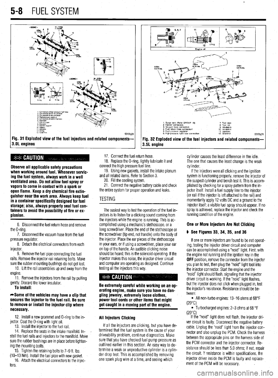
93155gx Fig. 31 Exploded view of the fuel injectors and related components-
s.OL engines
Observe all applicable safety precautions
when working around fuel. Whenever servic-
ing the fuel system, always work in a well
ventilated area. Do not allow fuel spray or
vapors to come in contact with a spark or
open flame. Keep a dry chemical fire extin-
guisher near the work area. Always keep fuel
in a container specifically designed for fuel
storage; also, always properly seal fuel con-
tainers to avoid the possibility of fire or ex-
plosion.
6. Disconnect the fuel return hose and remove
the O-ring.
7. Disconnect the vacuum hose from the fuel
pressure regulator.
8. Detach the electrical connectors from each
injector.
9. Remove the fuel pipe connectmg the fuel
rails. Remove the injector rail retaining bolts. Make
sure the rubber mounting bushings do not get lost.
10. Lift the rail assemblies up and away from the
engine.
11. Remove the injectors from the rail by pulling
gently. Discard the lower insulator.
To install:
*Some of the vehicles may have a clip that
secures the injector to the fuel rail. Be sure
to remove or install the injector clip where
necessary.
12. Install a new grommet and O-ring to the in-
jector. Coat the O-ring with light oil.
13. Install the injector to the fuel rail.
14. Replace the seats in the intake manifold. In-
stall the fuel rails and injectors to the manifold. Make
sure the rubber bushings are in place before tighten-
ing the mounting bolts.
15. Tighten the retaining bolts to 7-9 ft. Ibs.
(W-13 Nm) Install the fuel pipe with new gasket.
16. Attach the electrical connectors to the injec-
tors
Fig. 32 Exploded view of the fuel injectors and related components-
3.5L engine
17. Connect the fuel return hose.
18. Replace the O-ring, lightly lubricate it and
connect the high pressure fuel line.
19. Usmg new gaskets, install the intake plenum
and all related items. Refer to Section 3.
20. Fill the cooling system.
21. Connect the negative battery cable and check
the entire system for proper operation and leaks.
The easiest way to test the operation of the fuel in-
jectors is to listen for a clicking sound coming from
the injectors while the engine IS running. This is ac-
complished using a mechanic’s stethoscope, or a
long screwdriver. Place the end of the stethoscope or
the screwdriver (tip end, not handle) onto the body of
the injector. Place the ear pieces of the stethoscope
in your ears, or if using a screwdriver, place your ear
on top of the handle. An audible chcking noise
should be heard; this is the solenoid operating. If the
injector makes this noise, the injector driver circuit
and computer are operating as designed. Continue
testing all the injectors this way.
Be extremely careful while working on an op-
erating engine, make sure you have no dan-
gling jewelry, extremely loose clothes,
power tool cords or other items that might
get caught in a moving part of the ermine.
All Injectors Clicking
If all the injectors are clicking, but you have de-
termined that the fuel system is the cause of your
driveability problem, continue diagnostics. Make
sure that you have checked fuel pump pressure as
outlined earlier in this section. An easy way to de-
termine a weak or unproductive cylinder is a cylin-
der drop test. This is accomplished by removing
one spark plug wire at a time, and seeing which cylinder causes the least difference in the idle.
The one that causes the least change is the weak
cylinder.
If the injectors were all clicking and the ignition
system is functioning properly, remove the injector of
the suspect cylinder and bench test it. This is accom-
plished by checking for a spray pattern from the in-
jector itself Install a fuel supply line to the injector
(or rail if the injector is left attached to the rail) and
momentarily apply 12 volts DC and a ground to the
injector itself; a visible fuel spray should appear. If no
spray is achieved, replace the injector and check the
running condition of the engine.
One or More Injectors Are Not Clicking
6 See Figures 33, 34, 35, and 36
If one or more injectors are found to be not operat-
ing, testing the injector driver circuit and computer
can be accomplished using a “noid” light. First, with
the engine not running and the ignition key in the
OFF position, remove the connector from the injector
you plan to test, then plug the “noid” light tool into
the injector connector. Start the engine and the
“noid” light should flash, signaling that the injector
driver circuit is working. If the “noid” light flashes,
but the injector does not click when plugged in, test
the injectors resistance. Resistance should be be-
tween:
l All non-turbo engines: 13-16 ohms at 68°F
(20°C)
l Turbocharged engines: 2-3 ohms at 68 “F
(20°C)
If the “noid” light does not flash, the injector dri-
ver circuit is faulty. Disconnect the negative battery
cable. Unplug the “noid” light from the injector con-
nector and also unplug the PCM. Check the harness
between the appropriate pins on the harness side of
the PCM connector and the injector connector. Re-
sistance should be less than 5.0 ohms; if not, repair
the circuit. If resistance
IS within specifications, the
injector driver inside the PCM is faulty and replace-
ment of the PCM will be necessary.