1900 MITSUBISHI DIAMANTE fuel tank removal
[x] Cancel search: fuel tank removalPage 117 of 408
3-56 ENGINEANDENGINEOVERHAUL
,
F C
F
t
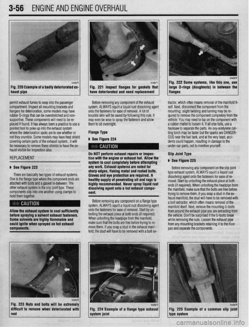
. Fig.
220 Example of a badly deteriorated ex- 1 Fig. 221 inspect flanges for gaskets that
haust pipe have deteriorated and need replacement Fig. 222 Some systems, like this one, use
)ermit exhaust fumes to seep into the passenger
:ompartment. Inspect all mounting brackets and
bangers for deterioration, some models may have
ubber O-rings that can be overstretched and non-
supportive. These components will need to be re-
Ilaced if found. It has always been a practice to use a
)ointed tool to poke up into the exhaist system
vhere the deterioration spots are to see whether or
d they crumble. Some models may have heat shield
:overing certain parts of the exhaust system , it will
te necessary to remove these shields to have the ex-
laust visible for inspection also. Before removing any component of the exhaust
system, ALWAYS squirt a Liquid rust dissolving agent
onto the fasteners for ease of removal. A lot of
knuckle skin will be saved by following this rule. It
may even be wise to spray the fasteners and allow
them to sit overniqht.
Flange Type
b See Figure 224 tractor, which oflen means removal of the manifold it
self. Next, disconnect the component from the
mounting; slight twisting and turning may be re-
quired to remove the component completely from thr
vehicle. You may need to tap on the component with
a rubber mallet to loosen it. If all else fails, use a
hacksaw to sep; arate the parts. An oxy-acetylene cut-
ting torch may I 3e faster but the sparks are OANGER-
OUS near the fuel tank, ant 1 at the very least, acci-
dents could happen, result ing in damage to the
under-car parts, not to mei ition yourself.
3EPLACEMEMT
1 See Figure 223
There are basically two types of exhaust systems.
)ne is the flange type where the component ends are
attached with bolts and a gasket in-between. The
)ther exhaust system is the slip joint type. These
:omponents slip into one another using clamps to
iold them together. Do NOT perform exhaust repairs or inspec-
tion with the engine or exhaust hot. Allow the
system to cool completely before attempting
any work. Exhaust systems are noted for
sharp edges, flaking metal and rusted bolts.
Gloves and eye protection are required. A
healthy supply of penetrating oil and
rags is
highly recommended. Never spray liquid rust
dissolving agent onto a hot exhaust compo-
nent. Slip Joint Type
V See Figure 225
Before removing any component on the slip joint
type exhaust system, ALWAYS squirt a liquid rust
dissolving agent onto the fasteners for ease of re-
moval. Start by unbolting the exhaust piece at both
ends (if required). When unbolting the headpipe fron
the manifold, make sure that the bolts are free before
trying to remove them. if you snap a stud in the ex-
haust manifold. the stud will have to be removed wit1
Before removing any component on a flange type
system, ALWAYS squirt a liquid rust dissolving agent a bolt extractor, which often means removal of the
._ manifold itself. Next. remove the mountina U-bolts
liiow the exhaust system to cool sufficiently
Iefore spraying a solvent exhaust fasteners.
Some solvents are highly flammable and
:ould ignite when sprayed on hot exhauti
:omponents. onto the fasteners for ease of removal. Start by un-
bolting the exhaust piece at both ends (if required).
When unbolting the headpipe from the manifold,
make sure that the bolts are free before trying to re-
move them. if you snap a stud in the exhaust mani-
fold, the stud will have to be removed with a bolt ex-
ka3p70 Fig. 223 Nuts and bolts will be extremely
difflcuit to remove when deteriorated with
rust Fig. 224 Example of a flange type exhaust
system joint from around the exhaust pipe you are ext&ting from
the vehicle. Don’t be surprised if the U-bolts break
while removing the nuts. Loosen the exhaust pipe
from any mounting brackets retaining it to the floor
pan and separate the components.
Fig. 225 Example of a common slip joini
type system
Page 145 of 408
4-2 DRIVEABILITYAND EMISSIONS CONTROLS
OPERATION
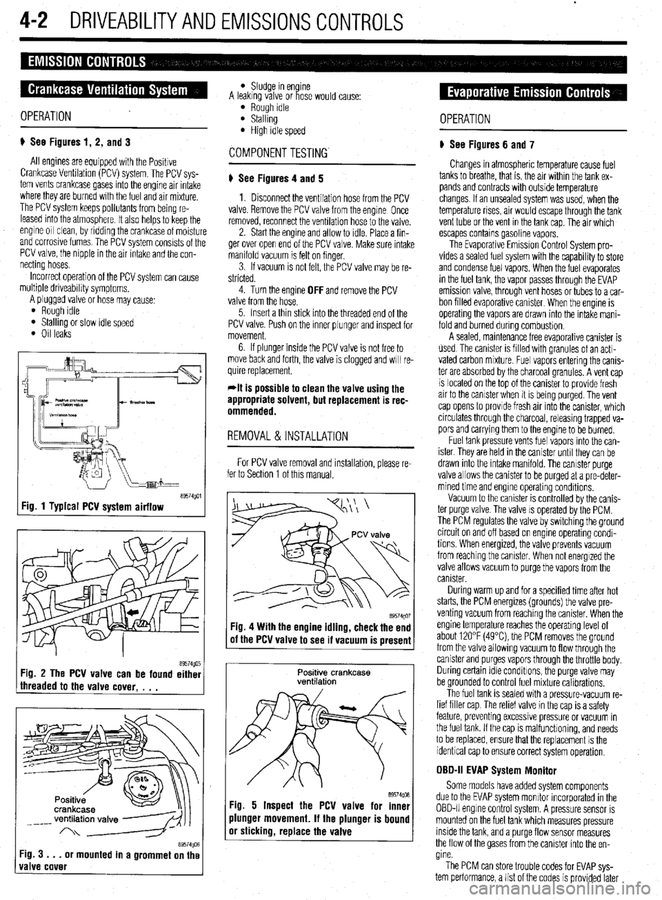
p See Figures 1, 2, and 3
All engines are equipped with the Positive
Crankcase Venhlation (PCV) system. The PCV sys-
tem vents crankcase gases into the engine air intake
where they are burned with the fuel and air mrxture.
The PCV system keeps pollutants from being re-
leased into the atmosphere It also helps to keep the
engine 011 clean, by ridding the crankcase of moisture
and corrosive fumes. The PCV system consists of the
PCV valve, the nipple in the air intake and the con-
necting hoses.
Incorrect operation of the PCV system can cause
multiple driveability symptoms.
A plugged valve or hose may cause’
l Rough Idle l Stalling or slow idle speed l Oil leaks
tT9574goi Fig. 1 Typical PCV system airflow
89574g0r5 Fig. 3 . . .
or mounted in a grommet on the
valve cover
l Sludge in en ine
A leakrng valve or ose would cause: i?
l Rough idle l Stalling l High idle speed
p See Figures 4 and 5
1. Disconnect the ventilation hose from the PCV
valve. Remove the PCV valve from the engine Once
removed, reconnect the ventilation hose to the valve.
2. Start the engine and allow to idle. Place a fin-
ger over open end of the PCV valve. Make sure intake
manifold vacuum is felt on finger.
3. If vacuum is not felt, the PCV valve may be re-
stricted.
4. Turn the engine
OFF and remove the PCV
valve from the hose.
5. Insert a thin stick into the threaded end of the
PCV valve. Push on the inner plunger and inspect for
movement.
6. If plunger inside the PCV valve is not free to
move back and forth, the valve is clogged and WIII re-
quire replacement.
*It is possible to clean the valve using the
appropriate solvent, but replacement is rec-
ommended.
REMOVAL&INSTALLATION
For PCV valve removal and installation, please re-
fer to Section 1 of this manual.
89574QO’ Fig. 4 With the engine idling, check the end
of the PCV valve to see if vacuum is present
Positive crankcase
ventilation
89574go6 Fig. 5 Inspect the PCV valve for inner
plunger movement. If the plunger is bound
or sticking, replace the valve OPERATION
p See Figures 6 and 7
Changes in atmospheric temperature cause fuel
tanks to breathe, that is, the air within the tank ex-
pands and contracts with outside temperature
changes. If an unsealed system was used, when the
temperature rises, air would escape through the tank
vent tube or the vent in the tank cap. The air which
escapes contains gasoline vapors.
The Evaporative Emission Control System pro-
vides a sealed fuel system with the capability to store
and condense fuel vapors. When the fuel evaporates
in the fuel tank, the vapor passes through the EVAP
emission valve, through vent hoses or tubes to a car-
bon filled evaporative canister. When the engine is
operahng the vapors are drawn into the intake mani-
fold and burned during combustion.
A sealed, maintenance free evaporative canister is
used The canister is filled wrth granules of an acti-
vated carbon mixture. Fuel vapors entering the canis-
ter are absorbed by the charcoal granules. A vent cap
is located on the top of the canister to provide fresh
air to the canister when it is being purged. The vent
cap opens to provide fresh air into the canister, which
circulates through the charcoal, releasing trapped va-
pors and carrying them to the engine to be burned.
Fuel tank pressure vents fuel vapors into the can-
ister. They are held in the canister until they can be
drawn into the intake manifold. The canister purge
valve allows the canister to be purged at a pre-deter-
mined time and engine operating conditions.
Vacuum to the canister is controlled by the canis-
ter purge valve. The valve IS operated by the PCM.
The PCM regulates the valve by switching the ground
circuit on and off based on engine operating condi-
tions When energized, the valve prevents vacuum
from reaching the canister. When not energized the
valve allows vacuum to purge the vapors from the
canister.
During warm up and for a specified time after hot
starts, the PCM energizes (grounds) the valve pre-
venting vacuum from reaching the canrster. When the
engine temperature reaches the operating level of
about 120°F (49°C) the PCM removes the ground
from the valve allowing vacuum to flow through the
canister and purges vapors through the throttle body.
During certain Idle conditions, the purge valve may
be grounded to control fuel mixture calibrations.
The fuel tank is sealed with a pressure-vacuum re-
lief filler cap. The relief valve in the cap is a safety
feature, preventing excessive pressure or vacuum in
the fuel tank. If the cap is malfunctioning, and needs
to be replaced, ensure that the replacement is the
identical cap to ensure correct system operation,
OBD-II EVAP System Monitor
Some models have added system components
due to the EVAP system monitor incorporated in the
OBD-II engrne control system. A pressure sensor is
mounted on the fuel tank which measures pressure
inside the tank, and a purge flow sensor measures
the flow of the gases from the canister into the en-
gine.
The PCM can store trouble codes for EVAP sys-
tem performance, a list of the codes is provided later
Page 188 of 408
BASIC FUEL SYSTEM DIAGNOSIS 5-2
FUEL LINES AND FllllNGS 5-2
FUEL LINE FITTINGS 5-2
REMOVAL &INSTALLATION 5-2
MULTI-POINT FUEL INJECTION
SYSTEM (MPI) 5-3
GENERALINFORMATION 5-3
FUELSYSTEM SERVICE
PRECAUTIONS 5-3
RELIEVING FUELSYSTEM
PRESSURE 5-3
THROTTLEBODY 5-3
REMOVAL & INSTALLATION 5-3
FUEL RAIL AND INJECTORS(S) 5-4
REMOVAL &INSTALLATION 5-4
TESTING 5-8
FUELPRESSUREREGULATOR 5-9
REMOVAL & INSTALLATION 5-9
PRESSURERELIEFVALVE 5-9
REMOVAL&INSTALLATION 5-9
FUEL TANK 5-10
TANKASSEMBLY 5-10
REMOVAL&INSTALLATION 5-10
Page 190 of 408
FUELSYSTEM 513
l Always replace worn fuel fitting O-rings with
new. Do not substitute fuel hose or equivalent, where
I
The Multi-Point Injection (MPI) system is electroni-
rally controlled by the Engine Control Module (ECM),
based on data from various sensors. The ECM controls
the fuel flow, idle speed and ignition timing. fuel pipe is installed.
Fuel is supplied to the injectors by an electric in-
tank fuel pump and is distributed to the respective in-
jectors via the main fuel pipe. The fuel pressure ap-
plied to the injector is constant and higher than the
pressure in the intake manifold. The pressure is con-
trolled by the fuel pressure regulator. The excess fuel
is returned to the fuel tank through the fuel return pipe.
When an electric current flows in the injector, the
injector valve is fully opened to supply fuel. Since the
fuel pressure is constant, the amount of the fuel in-
jetted from the injector into the manifold is increased
or decreased in proportion to the time the electric
current flows. Based on ECU signals, the injectors in-
ject fuel to the cylinder manifold ports in firing order. Fuel injection systems remain under pres-
sure after the engine has been turned OFF.
Properly relieve fuel pressure before discon-
neeting any fuel lines. Failure to do so may
result in fire or personal injury.
1. Turn the ignition to the OFF position.
2. Loosen the fuel filler cap to release fuel tank
pressure.
I
The flow rate of the air drawn through the air
cleaner is measured by the air flow sensor. The air
enters the air intake plenum or manifold through the
throttle body. In the intake manifold, the air is mixed
with the fuel from the injectors and is drawn into the
cylinder, The air flow rate is controlled according to
the degree of the throttle valve and the servo motor
openings. The system is monitored through a num-
ber of sensors which feed information on engine con-
ditions and requirements to the ECM. The ECM cal-
culates the injection time and rate according to the
signals from the sensors,
Safety is the most important factor when perform-
ing not only fuel system maintenance but any type of
maintenance. Failure to conduct maintenance and re-
pairs in a safe manner may result in serious personal
injury or death. Maintenance and testing of the vehi-
cle’s fuel system components can be accomplished
safely and effectively by adhering to the following
rules and guidelines.
l To avoid the possibility of fire and personal in-
jury, always disconnect the negative battery cable un-
less the repair or test procedure requires that battery
voltage be applied.
l Always relieve the fuel system pressure prior to
disconnecting any fuel system component (injector,
fuel rail, pressure regulator, etc.), fitting or fuel line
connection. Exercise extreme caution whenever re- Observe all applicable safety precautions
when working around fuel. Whenever servic-
ing the fuel system, always work in a well
ventilated area. Do not allow fuel spray or va-
pors to come in contact with a spark or open
flame. Keep a dry chemical fire extinguisher
near the work area. Always keep fuel in a con-
tainer specifically designed for fuel storage;
also, always properly seal fuel containers to
avoid the possibility of fire or explosion.
3. For the Mirage, Diamante, and 1994-00
Galant, remove the rear seat cushion, then remove
the service cover and detach the fuel pump harness
connector.
4. For the 1990-93 FWD Galant, detach the fuel
pump harness connector located in the area of the
fuel tank. It may be necessary to raise the vehicle to
access the connector.
5. For the 1990-93 AWD Galant, remove the car-
pet from the trunk, locate the fuel tank wiring at the
pump access cover, then detach the wiring.
6. Start the vehicle and allow it to run until it
stalls from lack of fuel. Turn the key to the OFF posi-
tion.
7. Disconnect the negative battery cable, then at-
tach the fuel pump connector. Install the access .
cover, cushion or carpet as necessary.
8. Wrap shop towels around the fitting that is be-
ing disconnected to absorb residual fuel in the lines.
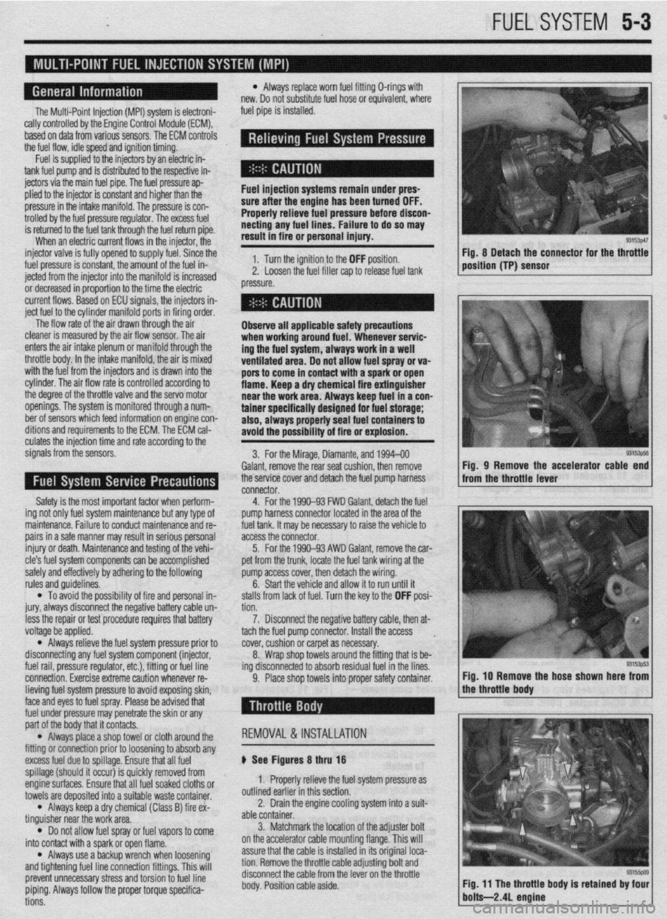
9. Place shop towels into proper safety container. Fig, 8 Detach the connector for the throttle
position (TP) sensor
93153ps5 Fig, 9 Remove the accelerator cable end
from the throttle lever
Fig. IO Remove the hose shown here from
lieving fuel system pressure to avoid exposing skin,
face and eyes to fuel spray. Please be advised that
fuel under pressure may penetrate the skin or any
part of the body that it contacts.
l Always place a shop towel or cloth around the
fitting or connection prior to loosening to absorb any
excess fuel due to spillage. Ensure that all fuel
spillage (should it occur) is quickly removed from
enginesurfaces. Ensure that all fuel soaked cloths or
towels are deposited into a suitable waste container.
l Always keep a dry chemical (Class B) fire ex-
tinguisher near the work area.
l Do not allow fuel spray or fuel vapors to come
into contact with a spark or open flame.
l Always use a backup wrench when loosening’
and tightening fuel line connection fittings. This will
prevent unnecessary stress and torsion to fuel line
piping. Always follow the proper torque specifica-
tions. REMOVAL &INSTALLATION
p See Figures 8 thru 18
1. Properly relieve the fuel system pressure as
outlined earlier in this section.
2. Drain the engine cooling system into a suit-
able container.
3. Matchmark the jocation of the adjuster bolt
on the accelerator cable mounting flange. This will
assure that the cable is installed in its original loca-
tion. Remove the throttle cable adjusting bolt and
disconnect the cable from the lever on the throttle
body. Position cable aside.
Page 197 of 408
5-10 FUELSYSTEM
1. _
Fuel tank pressure
-
relef vdive
REMOVAL &INSTALLATION
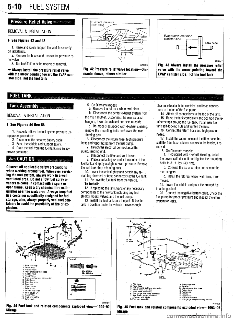
p See Figures 42 and 43
1. Raise and safely support the vehicle securely
on jackstands.
2. Remove the hoses and remove the pressure re-
lief valve.
3. The installation is the reverse of removal.
c, Always install the pressure relief valve
with the arrow pointing toward the EVAP can-
ister side, not the fuel tank 1 mame shown, others similar g3155g” Fig 42 Pressure relief valve location-llia
I I
Evaporatwe emlsslon
canister side
Tank side
+k
93155gt7 Fig. 43 Always install the pressure relief
valve with the arrow pointing toward the
EVAP canister side, not the fuel tank
REMOVAL&INSTALLATION
p See Figures 44 thru 58
1. Properly relieve the fuel system pressure us-
ing proper procedures.
2. Disconnect the negative battery cable.
3. Raise the vehicle and support safelv.
4. Drain the fuel from the fuel tank into an
ap- proved container.
Observe all applicable safety precautions
when working around fuel. Whenever servic-
ing the fuel system, always work in a well
ventilated area. Do not allow fuel spray or
vapors to come in contact with a spark or
open flame. Keep a dry chemical fire extin-
guisher near the work area. Always keep fuel
in a container specifically designed for fuel
storage; also, always properly seal fuel con-
tainers to avoid the possibility of fire or ex-
plosion.
5. On Diamante models:
a. Remove the left rear wheel well liner.
b Disconnect the center exhaust system from
the main muffler. Disconnect the rear exhaust
hangers, lower the exhaust and secure aside.
c. On models equipped with 4-wheel steering,
remove the mounting bolts and lower the rear
steering gear.
6. Disconnect the return hose, high pressure
hose and vapor hoses from the fuel pump.
7. Detach the electrical connectors at the
pump/sending unit.
8. Disconnect the filler and vent hoses.
s
9. Place a suitable jack under the center of the
fuel tank and apply a slight upward pressure. Remove
the fuel tank strap retaining nuts.
10. Lower the tank slightly and detach any re-
maining electrical or hose connectors at the fuel tank.
11. Remove the fuel tank from the vehicle.
To install: 12. If replacing the tank, transfer any necessary
components to the new tank including any heat
shields, hoses, valves, and the fuel pump.
13. Install the fuel tank onto the jack. Rarse the
tank in position under the vehicle. Leave enough
Tg. 44 Fuel tank and related components exploded view-1990-92
mirage
clearance to attach the electrical and hose connec-
tions to the top of the fuel pump.
14. Attach all connectrons to the top of the tank.
15. Raise the tank completely and position the re-
tainer straps around the fuel tank. Install new fuel
tank self-locking nuts and tighten the nuts.
16. Connect the return hose and high pressure
hoses.
17. Install the vapor hose and the filler hose. In-
stall the filler hose retainer screws to the fender, if re-
moved.
18. On Diamante models:
a. If equipped with 4-wheel steering, install
the power cylinder unit and tighten the mounting
bolts to 31 ft. Ibs. (43 Nm).
b. Connect the exhaust pipe and secure the
rear hangers.
c. Install the left rear wheel well liner, if re-
moved.
19. Lower the vehicle and pour the drained fuel
into the gas tank.
20. Connect the negative battery cable. Check the
fuel pump for proper pressure and inspect the entire
system for leaks.
:ig. 45
vlirage Fuel tank and related 93155(12E components exploded view-1993-96
Page 198 of 408
FUELSYSTEM 5-11
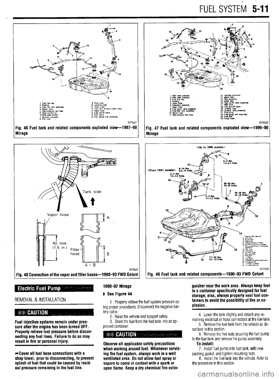
93155gZi Fig. 46 Fuel tank and related components exploded view-1997-98
Mirage
Vapor hose
Filler
hose
Fig. 48 Connection of the vapor and filler hoses-1990-93 FWD Galanl Qt. 49 Fuel tank and related components-1990-93 FWD Galant
1990-92 Mirage
p See Figure 44
REMOVAL &INSTALLATION
Fuel injection systems remain under pres-
sure after the engine has been turned OFF.
Properly relieve fuel pressure before discon-
necting any fuel lines. Failure to do so may
result in fire or personal iniury.
*Cover all fuel hose connections with a
shop towel, prior to disconnecting, to prevent
splash of fuel that could be caused by resid-
ual pressure remaining in the fuel line. Fig. 47 Fuel tank and related components exploded view-1999-00
1. Properly relieve the fuel system pressure us-
ing proper procedures. Disconnect the negative bat-
tery cable
2. Raise the vehicle and support safely.
3.
Dram the fuel from the fuel tank Into an ap-
proved container.
Observe all applicable safety precautions
when working around fuel. Whenever servic-
ing the fuel system, always work in a well
ventilated area. Do not allow fuel spray or
vapors to come in contact with a spark or
open flame. Keep a dry chemical fire extin- guisher near the work area. Always keep fuel
in a container specifically designed for fuel
storage; also, always properly seal fuel con-
tainers to avoid the possibility of fire or ex-
plosion.
4. Lower the tank slightly and detach any re-
maining electrical or hose connectors at the fuel tank.
5. Remove the fuel tank from the vehicle as de-
scribed In this section.
6 Remove the five nuts securing the fuel pump
to the fuel tank and remove the pump assembly.
To install:
7. Install fuel pump into fuel tank, with new
packing gasket, and tighten mounting nuts.
8. Install the fuel tank into the vehrcle. Refer to
the procedure in this section.
Page 200 of 408
FUELSYSTiM 5-13
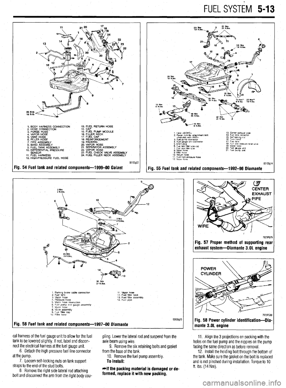
1. BODY HARNESS CONNECTION
2 HOSE CONNECTION
3 PURGE HOSE
4 VAPOR HOSE
5 VENT HOSE
6 FllLER HOSE
7 PIPE ASSEMBLY
8. BAND ASSEMBLY
9 FUEL TANK ASSEMBLY
10. DIFFERENTIAL PRESSURE
SENSOR
11 FUEL HARNESS
12 HIGH-PRESSURE FUEL HOSE 1; ;;JL RETURN HOSE
15 FUEL PUMP MODULE
16 FILLER NECK
17 FUEL CAP
IS REINFORCEMENT
19 PACKING
20 VAPOR HOSE
21 SEPARATOR ASSEMBLY
22 VAPOR HOSE
23 FUEL CHECK VALVE ASSEMBLY
24 FUEL FILLER NECK ASSEMBLY
Fig. 54 Fuel tank and related components-1999-00 Galant
:ia. 55 Fuel tank and related components-1992-96 Diamante
11. Align the 3 projections on packing with the
holes on the fuel pump and the nipples on the pump
facing the same direction as before removal.
12. Install the holdrng bolt through the bottom of
the tank. Make sure the gasket on the bolt is replaced
and is not pinched during installation. Torque to 10
ft. Ibs. (14 Nm).
1 PatkIng brake cable COnneCtlo” 11
2 Fuel tank “.qm hose
12 Fuel fllk, neck
3 “apot hose 13 Fuel filler assembly
4 Pressure hose 14
5 Vapor hose COnneCflOn Fuel p,pe
6 Fuel pump am gauge assembly
7 Vapor hose
8 Valve assembly
9 Fuel mer cap
10 FllkY hose
:ig. 56 Fuel tank and related components-1997-00 Diamante 93155g15
cal harness of the fuel gauge unit to allow for the fuel
pling. Lower the lateral rod and suspend from the
tank to be lowered slightly. If not, label and discon-
axle beam using wire.
nect the electrical harness at the fuel gauge unit.
6. Detach the high pressure fuel line connector 9. Remove the six retaining bolts and gasket
from the base of the tank.
at the pump.
10. Remove the fuel pump assembly.
7. Loosen self-lockinq nuts on tank suooort
To install: straps to the end of the stud bolts.
8 Remove the right side lateral rod attaching
bolt and drsconnect the arm from the right body cou- *If the packing material is damaged or de-
formed, replace it with new packing.
7923PG79 :ig. 57 Proper method of supporting real
rxhaust system-Diamante 3.01 engine
Page 201 of 408
.
5-14 FUEL SYSTEM
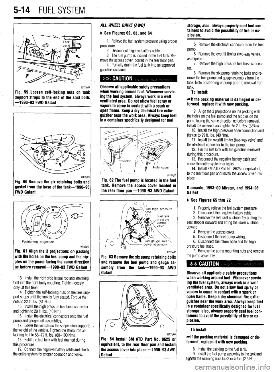
93155(10: ‘ig. 59 loosen self-locking nuts on tank
mpporf straps to the end of the stud bolts
-1990-93 FWD Galant
93i55Qo$ :ig. 60 Remove the six retaining bolts and
lasket from the base of the tank-1990-93
:WD Galant
Q m
0 a
cl@=
u a-
a al2
0
0
Q
a a
Posmdmng projectton 93155910 Fig. 61 Align the 3 projections on packing
with the holes on the fuel pump and the nip-
ples on the pump facing the same direction
as before removal-1990-93 FWD Galant
13. Install the right side lateral rod and attaching
bolt into the right body coupling. Tighten loosely
only, at this time.
14. Tighten the self-locking nuts on the tank sup-
port straps until the tank is fully seated. Torque the
nuts to 22 ft. Ibs. (31 Nm).
15. Install the high pressure fuel hose connector
and tighten to 29 ft. Ibs. (40 Nm).
16. Install the electrical connectors onto the fuel
pump and gauge unit assemblies.
17. Lower the vehicle so the suspension supports
the weight of the vehicle. Tighten the lateral rod at-
taching bolt to 58-72 ft Ibs. (So-100 Nm).
18. Refill the fuel tank with fuel drained during
this procedure.
19. Connect the negative battery cable and check
the entire system for proper operation and leaks. ALL WHEEL DRIVE (A WO)
# See Figures 62, 63, and 64
1. Relieve the fuel system pressure using proper
procedure.
2. Disconnect negative battery cable.
3. The fuel pump is located in the fuel tank. Re-
move the access cover located in the rear floor pan
4 Parbally drain the fuel tank into an approved
gasoline container.
Observe all applicable safety precautions
when workina around fuel. Whenever servic-
ing the fuel system, always work in a well
ventilated area. Do not allow fuel spray or
vapors to come in contact with a spark or
open flame. Keep a dry chemical fire extin-
guisher near the work area. Always keep fuel
in a container specifically designed for fuel
-ig. 62 The fuel pump is located in the fuel
r
ank. Remove the access cover located m
he rear floor pan -1990-93 AWD Galant
93155go7 Fig. 63 Remove the six pump retaining bolts
and remove the fuel pump and gauge as-
sembly from the tank-1990-93 AWD
1 Galant
93155goa Fig. 64 Install 3M ATD Part No. 8625 or
equivalent, to the rear floor pan and install
ihe access cover into place -1990-93 AWD
Ealant storage; also, always properly seal fuel con-
tainers to avoid the possibility of fire or ex-
plosion.
5 Remove the electrical connector from the fuel
pump.
6. Remove the overfill limiter (two-way valve),
as required.
7. Remove the high pressure fuel hose connec-
tor.
8. Remove the six pump retaming bolts and re-
move the fuel pump and gauge assembly from the
tank. Note positioning of pump prior to removal from
tank.
To install:
*If the packing material is damaged or de-
formed, replace it with new packing.
9. Align the 3 projections on the packing with
the holes on the fuel pump and the nipples on the
pump facmg the same direction as before removal.
Install the retainers and tlghten to 2 ft. Ibs. (3 Nm).
10. Install the high pressure hose connection and
tighten to 29 ft. Ibs. (40 Nm).
11. Install the overfill limiter (two-way valve) and
the electrical connector to the fuel pump.
12. Fill the fuel tank with the gasoline removed
during this procedure.
13. Reconnect the negative battery cable and
check the entire system for leaks.
14. Install 3M ATD Part No. 8625 or equivalent,
to the rear floor pan and install the access cover into
place.
Diamante, 1993-00 Mirage, and 1994-98
Galant
# See Figures 65 thru 72
1. Properly relieve the fuel system pressure.
2. Disconnect the negative battery cable.
3. Remove the rear seat cushion, by pulling the
seat stopper outward and lifting the lower cushion
upward.
4. Remove the access cover.
5. Disconnect the fuel pump wiring.
6. Disconnect the return hose and the high
pressure fuel hose.
7. Remove the pump mounting nuts and remove
the pump assembly.
Observe all applicable safety precautions
when working around fuel. Whenever servic-
ing the fuel system, always work in a well
ventilated area. Do not allow fuel spray or
vapors to come in contact with a spark or
open flame. Keep a dry chemical fire extin-
guisher near the work area. Always keep fuel
in a container specifically designed for fuel
storage; also, always properly seal fuel con-
tainers to avoid the possibility of fire or ex-
plosion.
To install:
rlf the packing material is damaged or de-
formed, replace it with new packing.
8. Install the packing to the fuel tank.
9. Install the fuel pump assembly to the tank and
tighten the retaining nuts to 22 inch Ibs. (2 5 Nm).