1900 MITSUBISHI DIAMANTE instrument panel
[x] Cancel search: instrument panelPage 9 of 408
.
l-10 GENERALINFORMATIONAND MAINTENANCE
which are available today will have two scales so the
The conversion factor chart is used by taking the
Standard or Metric measurements may easily be given specification and multiplying it by the neces-
taken. If any of the various measuring tools which are sary conversion factor. For instance, looking at the
available to you do not contain the same scale as first line, if you have a measurement in inches such
listed in the specifications, use the accompanying
as “free-play should be 2 in.” but your ruler reads
conversion factors to determine the proper value. only in millimeters, multiply 2 in. by the conversion factor of 25.4 to get the metric equivalent of 50.8mm.
Likewise, if the specification was given only in a Met-
ric measurement, for example in Newton Meters
(Nm), then look at the center column first. If the mea-
surement is 100 Nm, multiply it by the conversion
factor of 0.738 to get 73.8 ft. Ibs.
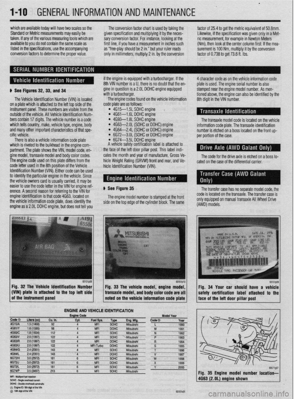
b See Figures 32,33, and 34
The Vehicle Identification Number (VIN) is located
on a plate which is attached to the left top side of the
instrument panel. These numbers are visible from the
outside of the vehicle. All Vehicle Identification Num-
bers contain 17 digits. The vehicle number is a code
which tells country, make, vehicle type, engine, body
and many other important characteristics of that spe-
cific vehicle.
There is also a vehicle information code plate
which is riveted to the bulkhead in the engine com-
partment. The plate shows the VIN, model code, en-
gine model, transaxle model and body color codes.
The engine code used on this plate differs from the
code letter used in the 8th position of the Vehicle
Identification Number (VIN). Either code can be used
to identify the particular engine in the vehicle. Since
the vehicle owners card is usually carried, it may be if the engine is equipped with a turbocharger. If the
8th VIN number is a U, there is no doubt that the en-
gine in question is a 2.OL DOHC engine equipped
with a turbocharger.
The engine codes found on the vehicle information
code plate are as follows:
l 4G15--1.5L SOHC engine l 4G61-1.6L DOHC engine l 4G93-1.8L SOHC engine l 4G63-2.OL (SOHC or DOHC) engine l 4G64-2.4L (SOHC or DOHC) engine l 6G72-3.OL (SOHC or DOHC) engine l 6G74-3.5L DOHC engine
A vehicle safety certification label is attached to
the face of the left door pillar post. This label indi-
cates the month and year of manufacture, Gross Ve-
hicle Weight Rating (GRVW) front and rear, and Ve-
hicle Identification Number (VIM). 4 character code as on the vehicle information code
plate is used. The engine serial number is also
stamped near the engine model number. As men-
tioned above, the engine can also be identified by the
8th digit in the VIN number.
The transaxle model code is located on the vehicle
information code plate. The transaxle identification
number is etched on a boss located on the front up-
per portion of the case.
The code for the drive axle is etched on a boss lo-
cated on the case of the differential carrier.
easier to use the code letter in the VIN for engine ref-
erence. A second reason for referring to the VIN for
engine identification is that code 4663, located on
the vehicle information code plate, does identify the
engine as a 2.OL DOHC engine, but does not tell you ) See Figure 35
The engine model number is stamped at the front
side on the top edge of the cylinder block. The same
Fig. 32 The Vehicle Identification Number
g3’51p’o of the instrument panel _I:^1 / Fig. 33 The vehicle model, engine model,
(VIN) plate is attached to the top left side
bansaxle model, and body color code are all
noted on the vehicle information code plate
ENGINE AND VEHiCLE IDENTlFlCATlON
EnglnCode
ModelYerr
todeal
LIten (cc)
Cu. In. W. Fuel+ Type m.hWg. Code@ Year ,G15JA 1.5 (1468) 92 4 MFI SOHC Mitsubishi
L 1990
IG61N 1.6(15QQ) 98 4 MFI DOHC
Mitsubishi M 1991
1G93lC 1.8 (1834) 112 4 MFI SOHC Mitsubishi N 1992
IG63N 2.0 (1997) 122 4 MFI SOHC “-Mitsubishi P
1993
!G63Fi 2.0 (1997) 122 4 MFI DOHC Mitsubishi
R 1994
,G63iU 2.0 (1997) 122 4 MFI-Tuibo DOHC Mitsubishi
S 1995
.GMffi 2.4 (2351) 143 4 MFI SOHC
Mitsubishi T 1996
iG64L 2.4 (2351) 143 4 MFI DOHC Mitsubishi V
lEzH 3.0 1997
(2972) 161 6 MFI SOHC Mitsubishi W 1998
;G7ZJ 3.0 (2Q72) 161 6 MFI GQHC Mitsubishi
~.. X 1999
iG7zL 3.0 (2972) 181
~ 6 MFI SOHC ___-___ Miisubishi
Y 2000
iG74lP 3.5 (3497) 213 6 MFI SOHC Miisubishi
The transfer case has no separate model code, the
code is located on the transaxle. The transfer case is
onlv eoUiODed on manual transaxle All Wheel Drive
(AWD)‘mbdels.
Fig. 34 Your car should have a vehicle
Fig. 35 Engine model number location-
4663 (2.OL) engine shown
Page 59 of 408
.
2-12 ENGINEELECTRICAL
*This section describes the operating prina
ciples of sending units, warning lights and
gauges. Sensors which provide information
to the Enafne Control Unit (ECU) or Electronic
or Power&in Control Module (FCM/PCM) are
covered in Section 4 of this manual.
Instrument panels contain a number of indicating
devices (gauges and warning lights). These devices
are composed of two separate components. One is
the sending unit, mounted on the engine or other re-
mote part of the vehicle, and the other is the actual
gauge or light in the instrument panel.
Several types of sending units exist, however most
can be characterized as being either a pressure type
or a resistance type. Pressure type sending units
convert liquid pressure into an electrical signal which
is sent to the gauge. Resistance type sending units
are most often used to measure temperature and use
variable resistance to control the current flow back to
the indicatinq device. Both types of sendinq units are
connected inseries by a wimto the batteryithiough
the ignition switch). When the ignition is turned ON,
current flows from the battery through the indicating
device and on to the sending unit.
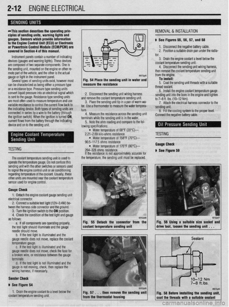
89572$43 Fig. 54 Place the sending unit in water and
measure the resistance
2. Disconnect the sending unit wiring harness
and remove the coolant temperature sending unit.
3. Place the sending unit tip in a pan of warm wa-
ter. Use a thermometer to measure the water tempera-
tl KP
L”,“.
4. Measure the resistance across the sending uni
terminals while the sending unit is in the water.
5. Note the ohm reading and compare to the fol-
lowing specifications: i, 56, 57, and 56
1. Disconnect the negative battery cable.
2. Position a suitable drain pan under the radia-
tor.
3. Drain the engine coolant a level below the
coolant temperature sending unit.
4. Disconnect the sending unit wiring harness,
then remove the coolant temperature sending unit
from the engine.
To install:
5. Coat the sending unit threads with a suitable
thread sealant.
6. Install the engine coolant temperature gauge
sending unit into the bore in the engine and tighten
to 7-8 ft. Ibs. (10-12 Nm).
7. Attach the electrical harness connector to the
sendina unit.
8. fill the cooling system to the proper level.
:onnect the negative battery cable.
l Water temperature of 68°F (2O”C)-
2.21-2.69 kilo-ohms resistance
l Water temperature of 158°F (7O’Ck
90.5-117.5 ohms resistance
TESTING l Water temperature of 176°F (8O”C)-
264-328 ohms resistance.
The coolant temperature sendina unit is used to
operate the temperature gauge. Donot confuse this
sending unit with the other switches or sensors used
to signal the engine control unit or air conditioning
regarding temperature of the coolant. Usually, these
other units are mounted near the coolant temoerature
sensor used for engine control. If the resistance is not approximately accurate for
the temperature, the sending unit must be replaced.
Gauge Check
1. Detach the engine coolant gauge sending unit
electrical connector.
2. Connect a suitable test liaht (12V-3.4W) be-
tween the harness side connector and the around.
I
3. Turn the ignition switch to the ON position.
4. Check the condition of the test light and gauge
as follows:
a. If all components are operating properly,
the test light should illuminate and the gauge
needle should move.
b. If the test light is illuminated and the
gauge needle does not move, replace the coolant
temperature gauge.
c. If the test light is illuminated and the
gauge needle does not move, check the fuse for
a broken wire, or resistance between the gauge
terminals
d. If the test light is not illuminated and the
gauge is not moving, check, then replace the
wiring harness, if necessar!y.
Sender Check
p See Figure 64
1. Drain the engine coolant to a level below the
coolant temperature sending unit Fig. 55 Detach the connector from the
coolant temperature sending unit
'ESTING
tauga Check
See Ftgure 69
Page 151 of 408
.
4-8 DRIVEABILITYAND EMISSIONS CONTROLS
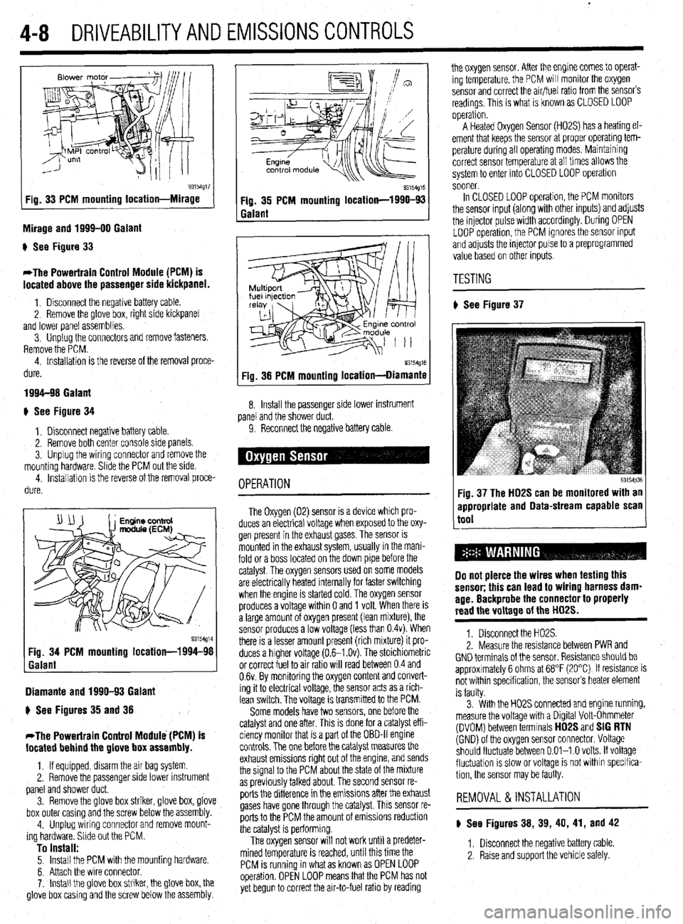
93154g17 Fig. 33 PCM mounting location-Mirage
Mirage and 1999-00 Galant
) See Figure 33
*The Powertrain Control Module (PCM) is
located above the passenger side kickpanel.
1. Disconnect the negative battery cable.
2. Remove the @love box, right side kickpanel
and lower panel assemblies.
3. Unplug the connectors and remove fasteners.
Remove the PCM.
4. Installation is the reverse of the removal proce-
dure.
1994-98 Galant
+ See Figure 34
1, Disconnect negative battery cable.
2. Remove both center console side panels.
3. Unplug the wiring connector and remove the
mounting hardware. Slide the PCM out the side.
4. installation is the reverse of the removal proce-
dure.
Diamante and 1990-93 Galant
) See Figures 35 and 38
*The Powertrain Control Module (PCM) is
located behind the glove box assembly.
1, If equipped, disarm the air bag system
2. Remove the passenger side lower instrument
panel and shower duct.
3. Remove the glove box striker, glove box, glove
box outer casing and the screw below the assembly.
4. Unplug wiring connector and remove mount-
ing hardware. Slide out the PCM.
To install: 5. Install the PCM with the mounting hardware.
6. Attach the wire connector.
7. Install the glove box striker, the glove box, the
glove box casing and the screw below the assembly.
Q3154g15 Fig. 35 PCM mounting location-1990-93
Galant
93154g16 Fig. 38 PCM mounting location-Diamante
8. Install the passenger side lower instrument
panel and the shower duct.
9. Reconnect the negative battery cable
OPERATION
The Oxygen (02) sensor is a device which pro-
duces an electrical voltage when exposed to the oxy-
gen present in the exhaust gases. The sensor is
mounted in the exhaust system, usually in the mani-
fold or a boss located on the down pipe before the
catalyst. The oxygen sensors used on some models
are electrically heated internally for faster switching
when the engine is started cold. The oxygen sensor
produces a voltage within 0 and 1 volt. When there is
a large amount of oxygen present (lean mixture), the
sensor produces a low voltage (less than 0.4~). When
there is a lesser amount present (rich mixture) it pro-
duces a higher voltage (0.6-I .Ov). The stoichiometric
or correct fuel to air ratio will read between 0.4 and
0.6~. By monitoring the oxygen content and convert-
ing it to electrical voltage, the sensor acts as a rich-
lean switch. The voltage is transmitted to the PCM.
Some models have two sensors, one before the
catalyst and one after. This is done for a catalyst eff i-
ciency monitor that is a part of the OBD-II engine
controls. The one before the catalyst measures the
exhaust emissions right out of the engine, and sends
the signal to the PCM about the state of the mixture
as previously talked about. The second sensor re-
ports the difference in the emissions after the exhaust
gases have gone through the catalyst. This sensor re-
ports to the PCM the amount of emissions reduction
the catalyst is performing.
The oxygen sensor will not work until a predeter-
mined temperature is reached, until this time the
PCM is running in what as known as OPEN LOOP
operation. OPEN LOOP means that the PCM has not
yet begun to correct the air-to-fuel ratio by reading the oxygen sensor. After the engine comes to operat-
ing temperature, the PCM will monitor the oxygen
sensor and correct the air/fuel ratio from the sensor’s
readings. This is what is known as CLOSED LOOP
operation.
A Heated Oxygen Sensor (H02S) has a heating el-
ement that keeps the sensor at proper operatmg tem-
perature during all operating modes. Maintaining
correct sensor temperature at all times allows the
system to enter into CLOSED LOOP operation
sooner.
In CLOSED LOOP operation, the PCM monitors
the sensor input (along with other inputs) and adjusts
the injector pulse width accordingly. During OPEN
LOOP operation, the PCM ignores the sensor input
and adjusts the injector pulse to a preprogrammed
value based on other inputs.
TESTING
# See Figure 37
93154p36 Fig. 37 The HD2S can be monitored with an
appropriate and Data-stream capable scan
tool
Do not pierce the wires when testing this
sensor; this can lead to wiring harness dam-
age. Backprobe the connector to properly
read the voltage of the HD2S.
1. Disconnect the H02S.
2. Measure the resistance between PWR and
GND terminals of the sensor. Resistance should be
approximately 6 ohms at 68°F (20°C) If resistance is
not within specification, the sensor’s heater element
is faulty.
3. With the H02S connected and engine running,
measure the voltage with a Digital Volt-Ohmmeter
(DVOM) between terminals
HD2S and SIG RTN (GND) of the oxygen sensor connector. Voltage
should fluctuate between 0.01-l .O volts. If voltage
fluctuation is slow or voltage is not within specifica-
tion, the sensor may be faulty.
REMOVAL &INSTALLATION
) See Figures 38, 39, 40, 41, and 42
1. Disconnect the negative battery cable
2. Raise and support the vehicle safely.
Page 169 of 408
4-26 DRIVEABILITYAND EMISSIONS CONTROLS
The Powertrain Control Module (PCM) monitors
the signals of input and output sensors, some all the
time and others at certain times and processes each
signal. When the PCM notices that an irregularity has
continued for a specified time or longer from when
the irregular signal was initially monitored, the PCM
judges that a malfunction has occurred and will
memorize the malfunction code. The code is then
stored in the memory of the PCM and is accessible
through the data link (diagnostic connector) with the
use of an electronic scan tool or a voltmeter.
CHECK ENGINE/MALFUNCTION
INDICATOR LIGHT
Among the on-board diagnostic items, a check
engine/malfunction indicator light comes on to notify
the driver of a emission control component irregular-
ity. If the irregularity detected returns to normal or the
PCM judges that the component has returned to nor-
mal, the check engine/malfunction indicator light will
be turned off Moreover, if the ignition is turned OFF
and then the engine is restarted, the check
engine/malfunction indicator light will not be turned
on unttl a malfunction is detected.
The check engine/malfunction indicator light will
come on immediately after the ignition switch is
turned ON. The light should stay lit for 5 seconds
and then will go off. This Indicates that the check en-
gine/malfunction indicator lamp is operating nor-
mally. This does not signify a problem with the sys-
tem.
*The check engine/malfunction indicator
lamp will come on when the terminal for the
ignition timing adjustment is shorted to
ground. Therefore, it is not abnormal that the
light comes on even when the terminal for ig-
nition timing is shorted at time of ignition
timing adjustment.
To test the light, perform the following:
1. Turn the ignition switch ON. Inspect the check
engine/malfunction indicator lamp for Illumination.
2. The light should be lit for 5 seconds and then
should go out.
3. If the lamp does not illuminate, check for open
circuit In the harness, blown fuse or blown bulb.
SERVICE PRECAUTIONS
l Before attachrng or detaching the PCM harness
connectors, make sure the ignition switch is OFF and
the negative battery cable is disconnected to avoid
the possibility of damage to the PCM.
l When performing PCM input/output signal di-
agnosis, remove the pin terminal retainer from the
connectors to make it easier to insert tester probes
into the connector.
l When attaching or detaching pin connectors ,
from the PCM, take care not to bend or break any pin
terminals. Check that there are no bends or breaks on
PCM pin terminals before attempting any connec-
tions.
l Before replacing any PCM, perform the PCM
input/output signal diagnosis to make sure the PCM
is functioning properly.
l When measuring supply voltage of PCM-con-
trolled components with a circuit tester, separate 1
tester probe from another. If the 2 tester probes acci-
dentally make contact with each other during mea-
surement, a short circuit WIII result and damage the
PCM.
# See Figures 83
and 84
Remember that the diagnostic trouble code identi-
fication refers only to the circuit, not necessarily to a
specific component. For example, fault code 14 may
indicate an error in the throttle position sensor cir-
cuit; it does not necessarily mean the TPS sensor has
failed Testing of all related wiring, connectors and
the sensor itself may be required to locate the prob-
lem.
The PCM memory is capable of storing multiple
codes. During diagnosis the codes will be transmlt-
ted in numerical order from lowest to highest, regard-
less of the order of occurrence. If multiple codes are
stored, always begin diagnostic work with the lowest
numbered code
Make a note of the following:
1. When battery voltage IS low, no detection of
failure is possible. Be sure to check the battery volt-
age and other conditions before starting the test.
2. Diagnostic items are erased if the battery or the
engine controller connection is detached. Do not dis- connect either of these components until the diag-
nostic material present in the PCM has been read
completely.
3. Be sure to attach and detach the scan tool to
the data link connector with the ignition key OFF. If
the scan tool in connected or disconnected with the
ignition key ON, diagnostic trouble codes may be
falsely stored and the engine warning light may be il-
luminated. WITHASCANTOOL
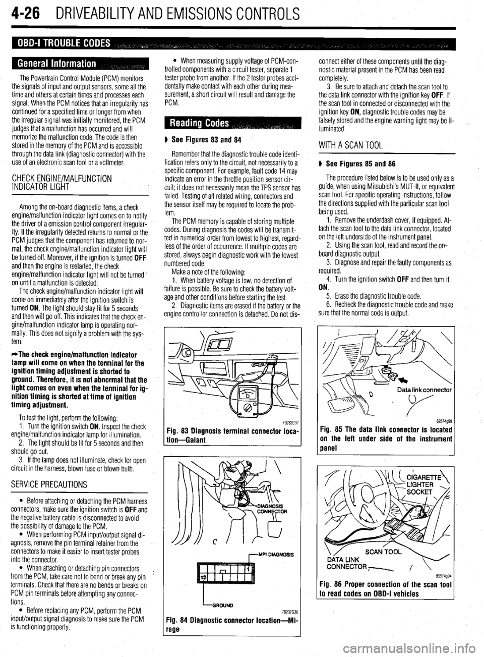
) See Figures 85 and 86
The procedure listed below is to be used only as a
guide, when using Mitsubishi’s MUT-II, or equivalent
scan tool. For specific operating instructions, follow
the directions supplied with the particular scan tool
bemg used.
1. Remove the underdash cover, if equipped. At-
tach the scan tool to the data link connector, located
on the left underside of the instrument panel.
2. Using the scan tool, read and record the on-
board diagnostic output.
3. Diagnose and repair the faulty components as
required
4. Turn the ignition switch OFF and then turn it
ON.
5. Erase the diagnostic trouble code.
6 Recheck the diaanostic trouble code and make
sure that the normal &de is output.
79232G37 89574g98 Fig. 83 Diagnosis terminal connector loca-
tion-Galant Fig. 85 The data link connector is located
on the left under side of the instrumeni
panel
,--MU DL4GNDSl.S
LGRDIJND
79232638
Fig. 84 Diagnostic connector Iocation-Mi-
‘age
ata link connector
89574994 Fig. 86 Proper connection of the scan tool to read codes on OBD-I vehicles
Page 170 of 408
DRIVEABILITYAND EMISSIONS CONTROLS 4-27
WITHOUTASCANTOOL
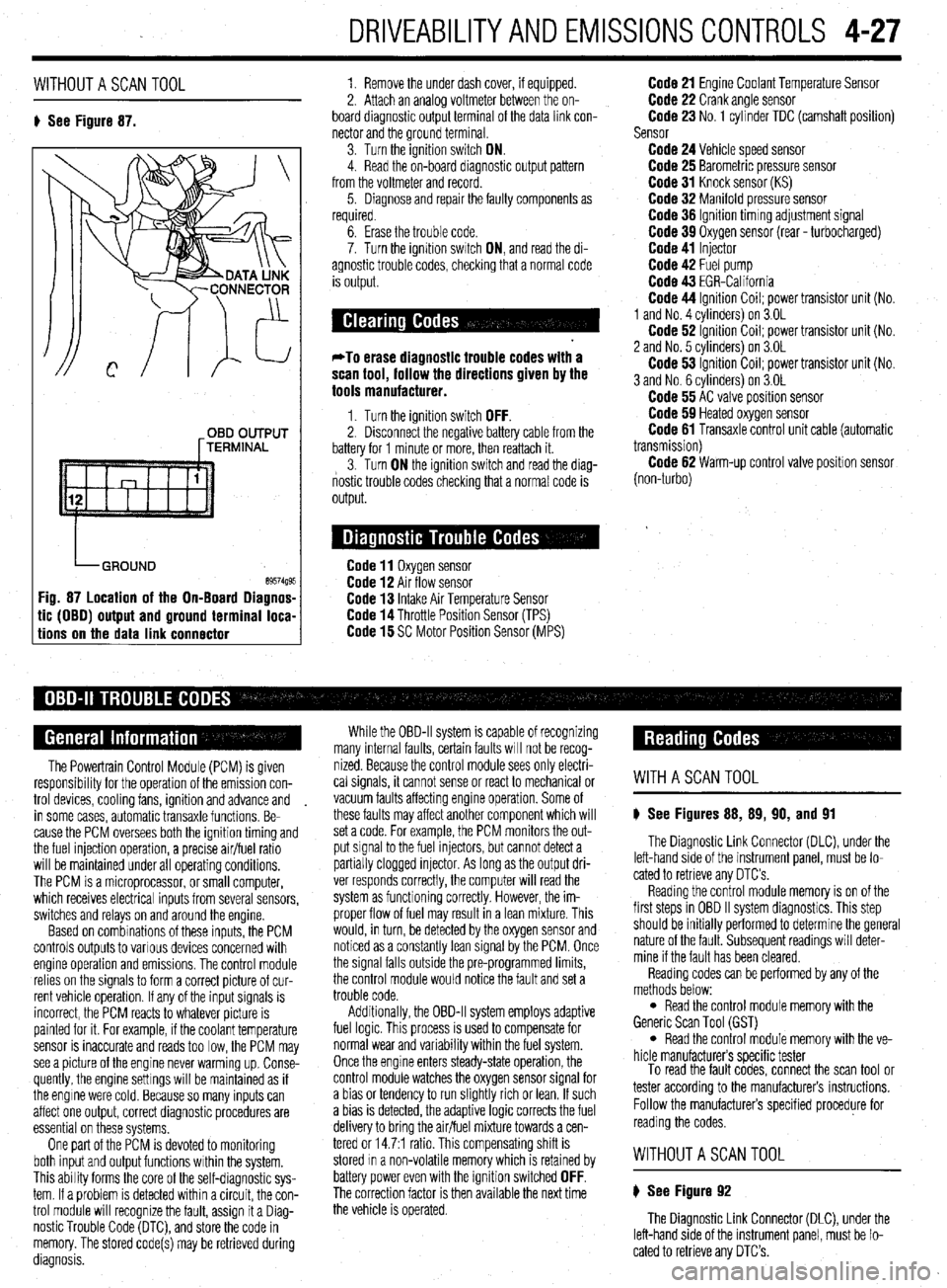
8 See Figure 87. 1. Remove the under dash cover, if equipped.
2. Attach an analoa voltmeter between the on-
board diagnostic outpit terminal of the data link con-
nector and the ground terminal
3. Turn the ignition switch ON.
4. Read the on-board diagnostic output pattern
from the voltmeter and record.
5. Diagnose and repair the faulty components as
required.
OBD OUTPUT
[TERMINAL
tic (OBO) output and ground terminal loca-
tions on the data link connector
6. Erase the trouble code.
7. Turn the ignition swatch ON, and read the di-
agnostic trouble codes, checking that a normal code
is output.
*To erase diagnostic trouble codes with a
scan tool, follow the directions given by the
tools manufacturer.
1. Turn the ignition switch OFF. 2. Disconnect the negative battery cable from the
battery for 1 minute or more, then reattach it.
3. Turn ON the ignition switch and read the diag-
nostic trouble codes checking that a normal code is
output.
Code 11 Oxygen sensor Code 12 Air flow sensor Code 13 Intake Air Temperature Sensor Code 14 Throttle Position Sensor (TPS) Code 15 SC Motor Position Sensor (MPS)
Code 21 Engine Coolant Temperature Sensor Code 22 Crank angle sensor Code 23 No. 1 cylinder TDC (camshaft position)
Sensor
Code 24 Vehicle speed sensor Code 25 Barometric pressure sensor Code 31 Knock sensor (KS) Code 32 Manifold pressure sensor Code 36 Ignition timmg adjustment signal Code 39 Oxygen sensor (rear - turbocharged) Code 41 Injector Code 42 Fuel pump Code 43 EGR-California Code 44 Ignition Coil; power transistor unit (No.
1 and No. 4 cvlinders) on 3.OL
Code 62 ignition Coil; power transistor unit (No.
2 and No. 5 cvlinders) on 3.OL
Code 53 ignition Coil; power transistor unit (No.
3 and No. 6 cylinders) on 3.OL
Code 55 AC valve position sensor Code 59 Heated oxygen sensor Code 61 Transaxle control unit cable (automatic
transmission)
Code 62 Warm-up control valve position sensor
(non-turbo)
The Powertrain Control Module (PCM) is given
responsibrlity for the operation of the emission con-
trol devices, cooling fans, ignition and advance and
in some cases, automatic transaxle functions. Be-
cause the PCM oversees both the ignition timing and
the fuel injection operation, a precise air/fuel ratio
will be maintained under all operating conditions,
The PCM is a microprocessor, or small computer,
which receives electrical inputs from several sensors,
switches and relays on and around the engine.
Based on combinations of these inputs, the PCM
controls outputs to various devices concerned with
engine operation and emissions. The control module
relies on the signals to form a correct picture of cur-
rent vehicle operation. If any of the input signals is
incorrect, the PCM reacts to whatever picture is
painted for it. For example, if the coolant temperature
sensor is inaccurate and reads too low, the PCM may
see a picture of the engine never warming up. Conse-
quently, the engine settings will be maintained as if
the engine were cold. Because so many inputs can
affect one output, correct diagnostic procedures are
essential on these systems,
One part of the PCM is devoted to monitoring
both input and output functions within the system.
This ability forms the core of the self-diagnostic sys-
tem. If a problem is detected within a circuit, the con-
trol module will recognize the fault, assign it a Diag-
nostic Trouble Code (DTC), and store the code in
memory. The stored code(s) may be retrieved during
diagnosis. While the OBD-II system is capable of recognizing
many internal faults, certain faults WIII not be recog-
nized. Because the control module sees only electri-
cal signals, it cannot sense or react to mechanical or
vacuum faults affecting engine operation. Some of
these faults may affect another component which will
set a code. For example, the PCM monitors the out-
put signal to the fuel injectors, but cannot detect a
partially clogged injector. As long as the output dri-
ver responds correctly, the computer will read the
system as functioning correctly. However, the im-
proper flow of fuel may result in a lean mixture. This
would, in turn, be detected by the oxygen sensor and
noticed as a constantly lean signal by the PCM. Once
the signal falls outside the pre-programmed limits,
the control module would notice the fault and set a
trouble code.
Additionally, the OBD-II system employs adaptive
fuel logic. This process is used to compensate for
normal wear and variability within the fuel system.
Once the engine enters steady-state operation, the
control module watches the oxygen sensor signal for
a bias or tendency to run slightly rich or lean. If such
a bias is detected, the adaptive logic corrects the fuel
delivery to bring the air/fuel mixture towards a cen-
tered or 14.7:1 ratio. This compensating shift is
stored In a non-volatile memory which is retained by
battery power even with the ignition switched
OFF. The correction factor is then available the next time
the vehicle is operated.
WITHASCANTOOL
8 See Figures 88, 89, 90, and 91
The Diagnostic Link Connector (DLC), under the
left-hand side of the instrument panel, must be lo-
cated to retrieve any OTC’s
Reading the control module memory is on of the
first steps in OBD II system diagnostics. This step
should be initially performed to determine the general
nature of the fault. Subsequent readings will deter-
mine if the fault has been cleared.
Reading codes can be performed by any of the
methods below:
l Read the control module memory with the
Generic Scan Tool (GST)
l Read the control module memory with the ve-
hicle manufacturers specific tester
To read the fault codes, connect the scan tool or
tester according to the manufacturers instructions.
Follow the manufacturers specified procedure for
reading the codes.
WITHOUTASCANTOOL
8 See Figure 92
The Diagnostic Link Connector (DLC), under the
left-hand side of the instrument panel, must be lo-
cated to retrieve any DTC’s.
Page 171 of 408
4-28 DRIVEABILITYAND EMISSIONS CONTROLS
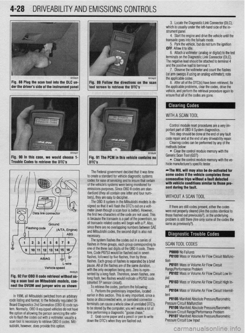
Fig. 88 Plug the scan tool into the DLC un-
Fig. 89 Follow the directions on the scan
der the driver’s side of the instrument panel
tool screen to retrieve the DTC’s 3. Locate the Diagnostic Link Connector (DLC),
which is usually under the left-hand side of the in-
strument panel.
4. Start the engine and drive the vehicle until the
transaxle goes into the failsafe mode.
5. Park the vehicle, but do not turn the ignition
OFF. Allow it to idle.
6. Attach a voltmeter (analog or digital) to the test
terminals on the Diagnostic Link Connector (DLC).
The negative lead should be attached to terminal 4
and the positive lead to terminal 1.
7. Observe the voltmeter and count the flashes
(or arm sweeps if using an analog voltmeter); note
the applicable codes.
- 8. After all of the DTC(s) have been retrieved, fix
the applicable problems, clear the codes, drive the
vehicle, and perform the retrieval procedure again to
ensure that all of the codes are gone.
WITHASCANTOOL
Control module reset procedures are a very im-
portant part of OBD II System diaqnostics.
This step should be done at the end of any fault
code repair and at the end of any driveability repair.
Clearing codes can be performed by any of the
Fig. 90 in this case, we would choor- A ’ ma*-. . . * .
Trouble Codes to retrieve the DTC’s
-.- -
A mere mar
. . methods below: l Clear the control module memory with the
se l-
I I ng. vi me rtim In mts venicie contains no Generic Scan Tool (GST) l DTC’S Clear the control module memory with the ve-
L’-‘m iufacturer’s specific tester
The Federal government decided that it was time
to create a standard for vehicle diagnostic systems
codes for ease of servicing and to insure that certain
of the vehicle’s systems were being monitored for
emissions purposes. Since OBD II codes are stan-
dardized (they all contain one letter and four num-
bers), they are easy to decipher.
The OBD II system in the Mitsubishi models is de-
signed so that it will flash the DTC’s out on a volt-
meter (even though a scan tool is better). However,
the first two characters of the code are not used. This
is because the transaxle is a part of the powertrain, so
all transaxle related codes will begin with a P. Also, *The MIL will may also be de-activated for
some codes if the vehicle completes three
consecutive trips without a fault detected
with vehicle conditions similar to those pre-
sent during the fault.
WITHOUTASCAN TOOL
If there are still codes p
resent, either the codes
were not properly cleared f
:Are the codes identical to
those flashed out previous
I$‘), or the underlying
problem is still there (Are I
only some of the codes the
same as oreviouslv?).
since there are no overlapping numbers between SAE
and Mitsubishi codes, the second digit is also not
necessary.
The system flashes the codes o
ut ma series of
flashes in
three nmm mh nrnlll -- J.-lr-, ---.. ~.--
p corresponding to
one of the
three last diaits of the OBD II code. There-
fore, Code WJJ wuuw UC:
IIKWAJ WI III XVWI flashes, followed by five flashes, then by three
flashes. Each group of flashes is se
pause. All of the flashes are of the (
witi the or$, nvrontinn hoinn mm sented by z
long flash,
(shorted Tt SWIWI LIIW. rparated by a brief
;ame duration,
88, “rw”I.‘L’“‘I uv,,,y LUI”.
Zero is repre-
1 long flash. Therefore, seven flashes, one
two flashes would indicate a PO702 code
3 nnmn^r ,.:*....:I I r
SCANTOOLCODES
. YYY” I ‘I” I cuI”I”.J PO100 Mass or Volume Air Flow Circuit Malfunc-
Lb
non
PO101 Mass orVolume Air Flow Circuit
Range/Performance Problem
PO102 Mass or Volume Air Flow Circuit Low In-
Put
.
To retrieve the codes, perform the following: PO103 Mass or Volume Air Flow Circuit High In-
i Put
1. Perform the preliminary inspection, located PO104 Mass or Volume Air Flow Circuit Intermit-
-;
Vehicle speed es446e35 Fig. 92 For OBO ii code retrieval without us-
ing a scan tool on Mitsubishi models, con-
nect the DVOM and jumper wire as shown
In 1996, all Mitsubishi switched from an arbitrary
code listing and format, to the federally regulated On
Board Diagnostics 2nd Generation (OBD II) code sys-
tern. Normally, OBD II equipped vehicles do not have
the option of allowing the person servicing the vehi-
cle to flash the codes out with a voltmeter; usually a
scan tool is necessary to retrieve OBD II codes. Mit-
subishi, however, does provide this option, earlier in this section. This is very important, since a
loose or disconnected wire, or corroded connector
terminals can cause a whole slew of unrelated DTC’s
to be stored by the computer; you will waste a lot of
time performing a diagnostic “goose chase.”
2. Grab some paper and a pencil or pen to write
down the DTC’s when they are flashed out. tent
PO105 Manifold Absolute Pressure/Barometric
Pressure Circuit Malfunction
PO106 Manifold Absolute Pressure/Barometric
Pressure Circuit Range/Performance Problem
PO107 Manifold Absolute Pressure/Barometric
Pressure Circuit Low Input
Page 204 of 408
UNDERSTANDING AND
TROUBLESHOOTING
ELECTRICAL SYSTEMS 6-2
BASIC ELECTRICALTHEORY 6-2
HOW DOES ELECTRICITY WORK:
THEWATERANALOGY 6-2
OHM'S LAW 6-2
ELECTRICALCOMPONENTS 6-2
POWERSOURCE 6-2
GROUND 6-3
PROTECTIVE DEVICES 6-3
SWITCHES&RELAYS 6-3
LOAD 6-3
WIRING & HARNESSES 6-3
CONNECTORS 6-4
TEST EQUIPMENT 6-4
JUMPER WIRES 6-4
TEST LIGHTS 6-4
MULTIMETERS 6-5
TROUBLESHOOTING ELECTRICAL
SYSTEMS 6-5
TESTING 6-5
OPEN CIRCUITS 6-5
SHORT CIRCUITS 6-6
VOLTAGE 6-6
VOLTAGE DROP 6-6
RESISTANCE 6-8
WIRE AND CONNECTORREPAIR 6-6
BATTERY CABLES 6-7
DISCONNECTING THE CABLES 6-7
AIR BAG (SUPPLEMENTAL
RESTRAINT SYSTEM) 6-7
GENERALINFORMATION 6-7
SERVICE PRECAUTIONS 6-7
DISARMING 6-7
REARMING 6-7
HEATING AND AIR
CONDITIONING 6-7
BLOWER MOTOR 6-7
REMOVAL &INSTALLATION 6-7
HEATER CORE 6-9 INSTRUMENTS AND SWITCHES 6-17
INSTRUMENTCLUSTER 6-17
REMOVAL &INSTALLATION 6-17
GAUGES 6-18
REMOVAL&INSTALLATION 6-18
WINDSHIELD WIPER SWITCH 6-19
REMOVAL&INSTALLATION 6-19
REARWINDOWWIPERSWITCH 6-19
REMOVAL &INSTALLATION 6-19
DIMMER SWITCH 6-19
REMOVAL & INSTALLATION 6-19 .
HEADLIGHT SWITCH 6-19
REMOVAL & INSTALLATION 6-19
LIGHTING 6-19
HEADLIGHTS 6-19
REMOVAL &INSTALLATION 6-19
AIMINGTHEHEADLIGHTS 6-20
SIGNAL AND MARKER LIGHTS 6-21
REMOVAL &INSTALLATION 6-21
CIRCUIT PROTECTION 6-27
FUSES 6-27
REPLACEMENT 6-27
FUSIBLE LINKS 6-27
CIRCUIT BREAKERS 6-28
RESETTING AND/OR
REPLACEMENT 6-28
FLASHERS 6-28
REPLACEMENT 6-28
WIRING DIAGRAMS 6-31
REMOVAL & INSTALLATION 6-9
AIR CONDITIONING COMPONENTS 6-11
REMOVAL & INSTALLATION 6-11
CONTROLCABLES 6-12
ADJUSTMENT 6-12
CONTROL PANEL 6-12
REMOVAL & INSTALLATION 6-12
CRUISE CONTROL 6-13
ENTERTAINMENT SYSTEMS 6-14
RADIO RECEIVER/AMPLIFIER/TAPE
PLAYER/CD PLAYER 6-14
SPEAKERS 6-14
REMOVAL & INSTALLATION 6-14
WINDSHIELD WIPERS AND
WASHERS 6-15
WINDSHIELD WIPER BLADE AND
ARM 6-15
REMOVAL & INSTALLATION 6-15
WINDSHIELD WIPER MOTOR 6-16 _
REMOVAL &INSTALLATION 6-16
WINDSHIELD WASHER PUMP 6-17
REMOVAL &INSTALLATION 6-17
Page 207 of 408
I
6-4 CHASSIS ELECTRICAL
I
printed circuit is sandwiched between two sheets of
plastic for more protection and flexibility. A complete l Weatherproof-these connectors are most the jumper wire is of too small a gauge, it
printed circuit, consisting of conductors, insulating commonly used where the connector is exposed to
may overheat and possibly melt. Never use
material and connectors for lamps or other compo- the elements. Terminals are protected against mois-
nents is called a printed circuit board. Printed cir- ture and dirt by sealing rings which provide a weath- jumpers to bypass high resistance loads in a
et-tight seal. All repairs require the use of a special circuit. Bypassing resistances, in effect, cre-
cuitry is used in place of individual wires or har- ates a short circuit. This may, in turn, cause
nesses in places where space is limited, such as terminal and the tool required to service it. Unlike
behind instrument panels. standard blade type terminals, these weatherproof damage and fire. Jumper wires should only
be used to bypass lengths of wire or to simu-
Since automotive electrical systems are very sen- terminals cannot be straightened once they are bent. late switches.
sitive to changes in resistance, the selection of prop- ‘Make certain that the connectors are properly seated
erly sized wires is critical when systems are repaired, and all of the sealing rings are in place when con-
netting leads. Jumper wires are simple, yet extremely valuable,
A loose or corroded connection or a replacement wire pieces of test equipment. They are basically test wires
that is too small for the circuit will add extra resis-
l Molded-these connectors require complete which are used to bypass sections of a circuit. Al-
replacement of the connector if found to be defective.
tance and an additional voltage drop to the circuit. though jumper wires can be purchased, they are usu-
The wire gauge number is an expression of the This means splicing a new connector assembly into ally fabricated from lengths of standard automotive
cross-section area of the conductor. Vehicles from the harness. All splices should be soldered to insure
proper contact. Use care when probing the connec- wire and whatever type of connector (alligator clip,
countries that use the metric system will typically de- spade connector or pin connector) that is required for
scribe the wire size as its cross-sectional area in tions or replacing terminals in them, as it is possible
square millimeters. In this method, the larger the to create a short circuit between opposite terminals. If the particular application being tested. In cramped,
hard-to-reach areas, it is advisable to have insulated
wire, the greater the number. Another common sys- this happens to the wrong terminal pair, it is possible
to damage certain components. Always use jumper boots over the jumper wire terminals in order to pre-
tern for expressing wire size is the American Wire vent accidental grounding. It is also advisable to in-
Gauge (AWG) system. As gauge number increases, wires between connectors for circuit checking and
NEVER probe through weatherproof seals. elude a standard automotive fuse in any jumper wire.
area decreases and the wire becomes smaller. An 18
gauge wire is smaller than a 4 gauge wire. A wire
l Hard Shell-unlike molded connectors, the This is commonly referred to as a “fused jumper”. By
inserting an in-line fuse holder between a set of test
terminal contacts in hard-shell connectors can be re-
with a higher gauge number will carry less current
placed. Replacement usually involves the use of a leads, a fused jumper wire can be used for bypassing :
than a wire with a lower gauge number. Gauge wire open circuits. Use a 5 amp fuse to provide protection
size refers to the size of the strands of the conductor, special terminal removal tool that depresses the lock- against voltage spikes.
not the size of the complete wire with insulator. It is ing tangs (barbs) on the connector terminal and al-
lows the connector to be removed from the rear of the Jumper wires are used primarily to locate open
possible, therefore, to have two wires of the same
shell. The connector shell should be replaced if it electrical circuits, on either the ground (-) side of the
gauge with different diameters because one may have
thicker insulation than the other. shows any evidence of burning, melting, cracks, or circuit or on the power (+) side. If an electrical corn-
breaks. Replace individual terminals that are burnt, ponent fails to operate, connect the jumper wire be-
It is essential to understand how a circuit works
corroded, distorted or loose. tween the component and a good ground. If the corn-
before trying to figure out why it doesn’t. An electrical ponent operates only with the jumper installed, the
schematic shows the electrical current paths when a ground circuit is open. If the ground circuit is good,
circuit is operating properly. Schematics break the but the component does not operate, the circuit be-
entire electrical system down into individual circuits. tween the power feed and component may be open. ’
In a schematic, usually no attempt is made to repre- Pinpointing the exact cause of trouble in an elec- By moving the jumper wire successively back from
trical circuit is most times accomplished by the use the component toward the power source, you can
; : sent wiring and components as they physically ap-
pear on the vehicle; switches and other components of special test equipment. The following describes isolate the area of the circuit where the open is lo-
are shown as simply as possible. Face views of har- different types of commonly used test equipment and cated. When the component stops functioning, or the f
j
ness connectors show the cavity or terminal locations briefly explains how to use them in diagnosis. In ad- power is cut off, the open is in the segment of wire j
in all multi-pin connectors to help locate test points. dition to the information covered below, the tool between the jumper and the point previously tested.
! manufacturer’s instructions booklet (provided with You can sometimes connect the jumper wire di-
the tester) should be read and clearly under.$ood be- rectly from the battery to the “hot” terminal of the I
CONNECTORS 1 fore attempting any test procedures. component, but first make sure the component uses 1
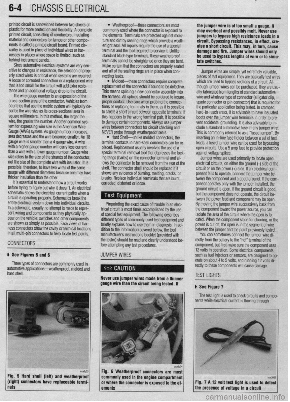
# See Figures 5 and 6 JUMPER WIRES 12 volts in operation. Some electrical components, i
such as fuel injectors or sensors, are designed to op-
Three types of connectors are commonly used in erate on about 4 to 5 volts, and running 12 volts di- j
)
automotive applications-weatherproof, molded and rectly to these components will cause damage.
hard shell.
Never use jumper wires made from a thinner TEST LIGHTS I
gauge wire than the circuit being tested. If
# See Figure 7
The test light is used to check circuits and compo-
I nents while electrical current is flowing through
Fig. 5 Hard shell (left) and weatherproof
(right) connectors have replaceable termi- Fig. 7 A 12 volt test light is used to di%
nals
ements 1 the presence of voltage in a circuit