1900 MITSUBISHI DIAMANTE tow bar
[x] Cancel search: tow barPage 170 of 408
DRIVEABILITYAND EMISSIONS CONTROLS 4-27
WITHOUTASCANTOOL
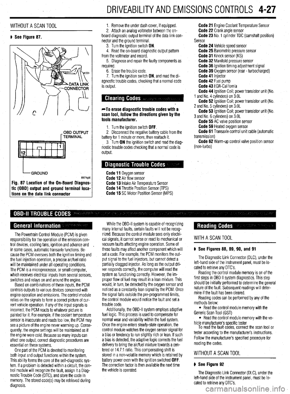
8 See Figure 87. 1. Remove the under dash cover, if equipped.
2. Attach an analoa voltmeter between the on-
board diagnostic outpit terminal of the data link con-
nector and the ground terminal
3. Turn the ignition switch ON.
4. Read the on-board diagnostic output pattern
from the voltmeter and record.
5. Diagnose and repair the faulty components as
required.
OBD OUTPUT
[TERMINAL
tic (OBO) output and ground terminal loca-
tions on the data link connector
6. Erase the trouble code.
7. Turn the ignition swatch ON, and read the di-
agnostic trouble codes, checking that a normal code
is output.
*To erase diagnostic trouble codes with a
scan tool, follow the directions given by the
tools manufacturer.
1. Turn the ignition switch OFF. 2. Disconnect the negative battery cable from the
battery for 1 minute or more, then reattach it.
3. Turn ON the ignition switch and read the diag-
nostic trouble codes checking that a normal code is
output.
Code 11 Oxygen sensor Code 12 Air flow sensor Code 13 Intake Air Temperature Sensor Code 14 Throttle Position Sensor (TPS) Code 15 SC Motor Position Sensor (MPS)
Code 21 Engine Coolant Temperature Sensor Code 22 Crank angle sensor Code 23 No. 1 cylinder TDC (camshaft position)
Sensor
Code 24 Vehicle speed sensor Code 25 Barometric pressure sensor Code 31 Knock sensor (KS) Code 32 Manifold pressure sensor Code 36 Ignition timmg adjustment signal Code 39 Oxygen sensor (rear - turbocharged) Code 41 Injector Code 42 Fuel pump Code 43 EGR-California Code 44 Ignition Coil; power transistor unit (No.
1 and No. 4 cvlinders) on 3.OL
Code 62 ignition Coil; power transistor unit (No.
2 and No. 5 cvlinders) on 3.OL
Code 53 ignition Coil; power transistor unit (No.
3 and No. 6 cylinders) on 3.OL
Code 55 AC valve position sensor Code 59 Heated oxygen sensor Code 61 Transaxle control unit cable (automatic
transmission)
Code 62 Warm-up control valve position sensor
(non-turbo)
The Powertrain Control Module (PCM) is given
responsibrlity for the operation of the emission con-
trol devices, cooling fans, ignition and advance and
in some cases, automatic transaxle functions. Be-
cause the PCM oversees both the ignition timing and
the fuel injection operation, a precise air/fuel ratio
will be maintained under all operating conditions,
The PCM is a microprocessor, or small computer,
which receives electrical inputs from several sensors,
switches and relays on and around the engine.
Based on combinations of these inputs, the PCM
controls outputs to various devices concerned with
engine operation and emissions. The control module
relies on the signals to form a correct picture of cur-
rent vehicle operation. If any of the input signals is
incorrect, the PCM reacts to whatever picture is
painted for it. For example, if the coolant temperature
sensor is inaccurate and reads too low, the PCM may
see a picture of the engine never warming up. Conse-
quently, the engine settings will be maintained as if
the engine were cold. Because so many inputs can
affect one output, correct diagnostic procedures are
essential on these systems,
One part of the PCM is devoted to monitoring
both input and output functions within the system.
This ability forms the core of the self-diagnostic sys-
tem. If a problem is detected within a circuit, the con-
trol module will recognize the fault, assign it a Diag-
nostic Trouble Code (DTC), and store the code in
memory. The stored code(s) may be retrieved during
diagnosis. While the OBD-II system is capable of recognizing
many internal faults, certain faults WIII not be recog-
nized. Because the control module sees only electri-
cal signals, it cannot sense or react to mechanical or
vacuum faults affecting engine operation. Some of
these faults may affect another component which will
set a code. For example, the PCM monitors the out-
put signal to the fuel injectors, but cannot detect a
partially clogged injector. As long as the output dri-
ver responds correctly, the computer will read the
system as functioning correctly. However, the im-
proper flow of fuel may result in a lean mixture. This
would, in turn, be detected by the oxygen sensor and
noticed as a constantly lean signal by the PCM. Once
the signal falls outside the pre-programmed limits,
the control module would notice the fault and set a
trouble code.
Additionally, the OBD-II system employs adaptive
fuel logic. This process is used to compensate for
normal wear and variability within the fuel system.
Once the engine enters steady-state operation, the
control module watches the oxygen sensor signal for
a bias or tendency to run slightly rich or lean. If such
a bias is detected, the adaptive logic corrects the fuel
delivery to bring the air/fuel mixture towards a cen-
tered or 14.7:1 ratio. This compensating shift is
stored In a non-volatile memory which is retained by
battery power even with the ignition switched
OFF. The correction factor is then available the next time
the vehicle is operated.
WITHASCANTOOL
8 See Figures 88, 89, 90, and 91
The Diagnostic Link Connector (DLC), under the
left-hand side of the instrument panel, must be lo-
cated to retrieve any OTC’s
Reading the control module memory is on of the
first steps in OBD II system diagnostics. This step
should be initially performed to determine the general
nature of the fault. Subsequent readings will deter-
mine if the fault has been cleared.
Reading codes can be performed by any of the
methods below:
l Read the control module memory with the
Generic Scan Tool (GST)
l Read the control module memory with the ve-
hicle manufacturers specific tester
To read the fault codes, connect the scan tool or
tester according to the manufacturers instructions.
Follow the manufacturers specified procedure for
reading the codes.
WITHOUTASCANTOOL
8 See Figure 92
The Diagnostic Link Connector (DLC), under the
left-hand side of the instrument panel, must be lo-
cated to retrieve any DTC’s.
Page 207 of 408
I
6-4 CHASSIS ELECTRICAL
I
printed circuit is sandwiched between two sheets of
plastic for more protection and flexibility. A complete l Weatherproof-these connectors are most the jumper wire is of too small a gauge, it
printed circuit, consisting of conductors, insulating commonly used where the connector is exposed to
may overheat and possibly melt. Never use
material and connectors for lamps or other compo- the elements. Terminals are protected against mois-
nents is called a printed circuit board. Printed cir- ture and dirt by sealing rings which provide a weath- jumpers to bypass high resistance loads in a
et-tight seal. All repairs require the use of a special circuit. Bypassing resistances, in effect, cre-
cuitry is used in place of individual wires or har- ates a short circuit. This may, in turn, cause
nesses in places where space is limited, such as terminal and the tool required to service it. Unlike
behind instrument panels. standard blade type terminals, these weatherproof damage and fire. Jumper wires should only
be used to bypass lengths of wire or to simu-
Since automotive electrical systems are very sen- terminals cannot be straightened once they are bent. late switches.
sitive to changes in resistance, the selection of prop- ‘Make certain that the connectors are properly seated
erly sized wires is critical when systems are repaired, and all of the sealing rings are in place when con-
netting leads. Jumper wires are simple, yet extremely valuable,
A loose or corroded connection or a replacement wire pieces of test equipment. They are basically test wires
that is too small for the circuit will add extra resis-
l Molded-these connectors require complete which are used to bypass sections of a circuit. Al-
replacement of the connector if found to be defective.
tance and an additional voltage drop to the circuit. though jumper wires can be purchased, they are usu-
The wire gauge number is an expression of the This means splicing a new connector assembly into ally fabricated from lengths of standard automotive
cross-section area of the conductor. Vehicles from the harness. All splices should be soldered to insure
proper contact. Use care when probing the connec- wire and whatever type of connector (alligator clip,
countries that use the metric system will typically de- spade connector or pin connector) that is required for
scribe the wire size as its cross-sectional area in tions or replacing terminals in them, as it is possible
square millimeters. In this method, the larger the to create a short circuit between opposite terminals. If the particular application being tested. In cramped,
hard-to-reach areas, it is advisable to have insulated
wire, the greater the number. Another common sys- this happens to the wrong terminal pair, it is possible
to damage certain components. Always use jumper boots over the jumper wire terminals in order to pre-
tern for expressing wire size is the American Wire vent accidental grounding. It is also advisable to in-
Gauge (AWG) system. As gauge number increases, wires between connectors for circuit checking and
NEVER probe through weatherproof seals. elude a standard automotive fuse in any jumper wire.
area decreases and the wire becomes smaller. An 18
gauge wire is smaller than a 4 gauge wire. A wire
l Hard Shell-unlike molded connectors, the This is commonly referred to as a “fused jumper”. By
inserting an in-line fuse holder between a set of test
terminal contacts in hard-shell connectors can be re-
with a higher gauge number will carry less current
placed. Replacement usually involves the use of a leads, a fused jumper wire can be used for bypassing :
than a wire with a lower gauge number. Gauge wire open circuits. Use a 5 amp fuse to provide protection
size refers to the size of the strands of the conductor, special terminal removal tool that depresses the lock- against voltage spikes.
not the size of the complete wire with insulator. It is ing tangs (barbs) on the connector terminal and al-
lows the connector to be removed from the rear of the Jumper wires are used primarily to locate open
possible, therefore, to have two wires of the same
shell. The connector shell should be replaced if it electrical circuits, on either the ground (-) side of the
gauge with different diameters because one may have
thicker insulation than the other. shows any evidence of burning, melting, cracks, or circuit or on the power (+) side. If an electrical corn-
breaks. Replace individual terminals that are burnt, ponent fails to operate, connect the jumper wire be-
It is essential to understand how a circuit works
corroded, distorted or loose. tween the component and a good ground. If the corn-
before trying to figure out why it doesn’t. An electrical ponent operates only with the jumper installed, the
schematic shows the electrical current paths when a ground circuit is open. If the ground circuit is good,
circuit is operating properly. Schematics break the but the component does not operate, the circuit be-
entire electrical system down into individual circuits. tween the power feed and component may be open. ’
In a schematic, usually no attempt is made to repre- Pinpointing the exact cause of trouble in an elec- By moving the jumper wire successively back from
trical circuit is most times accomplished by the use the component toward the power source, you can
; : sent wiring and components as they physically ap-
pear on the vehicle; switches and other components of special test equipment. The following describes isolate the area of the circuit where the open is lo-
are shown as simply as possible. Face views of har- different types of commonly used test equipment and cated. When the component stops functioning, or the f
j
ness connectors show the cavity or terminal locations briefly explains how to use them in diagnosis. In ad- power is cut off, the open is in the segment of wire j
in all multi-pin connectors to help locate test points. dition to the information covered below, the tool between the jumper and the point previously tested.
! manufacturer’s instructions booklet (provided with You can sometimes connect the jumper wire di-
the tester) should be read and clearly under.$ood be- rectly from the battery to the “hot” terminal of the I
CONNECTORS 1 fore attempting any test procedures. component, but first make sure the component uses 1
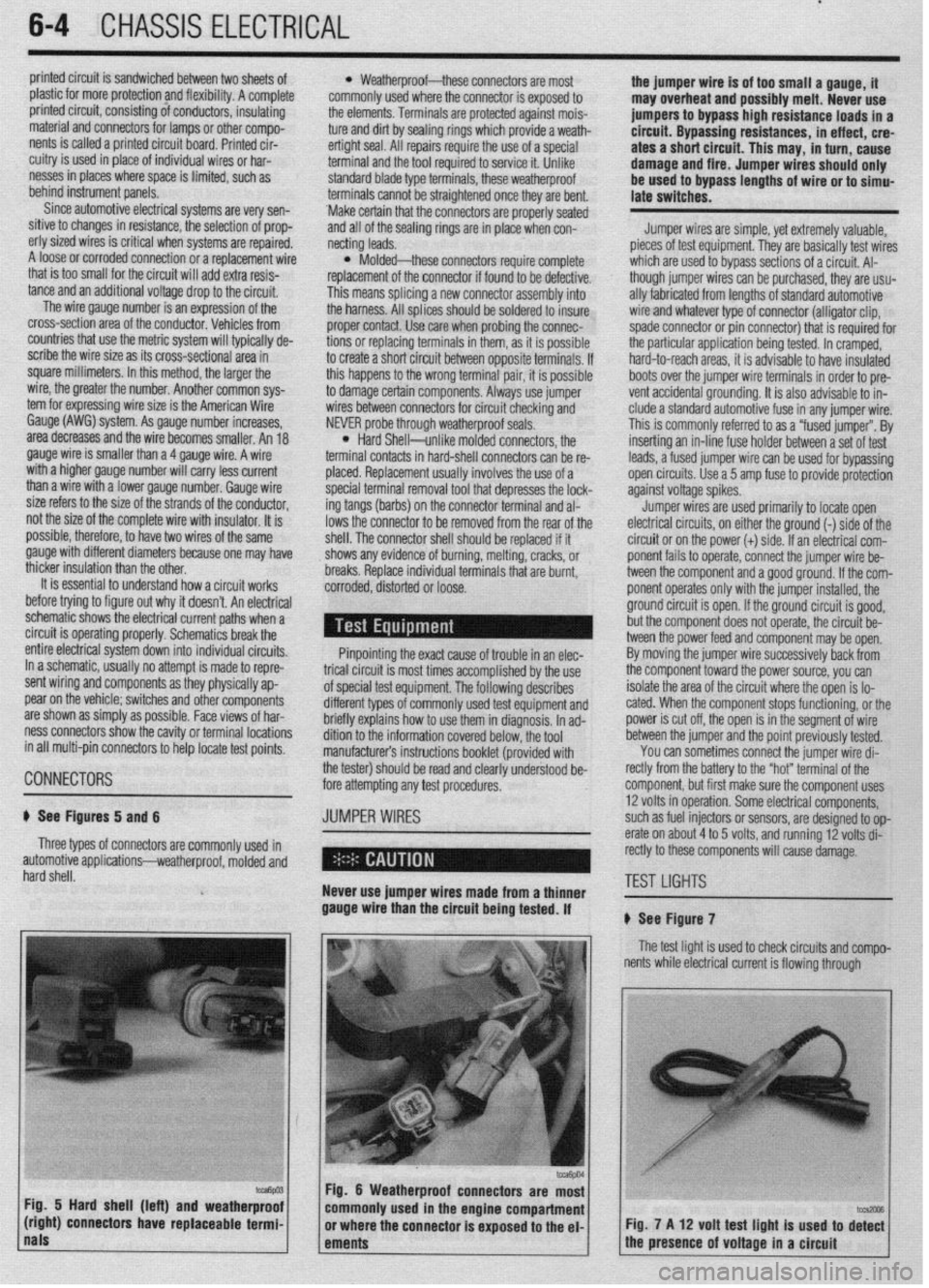
# See Figures 5 and 6 JUMPER WIRES 12 volts in operation. Some electrical components, i
such as fuel injectors or sensors, are designed to op-
Three types of connectors are commonly used in erate on about 4 to 5 volts, and running 12 volts di- j
)
automotive applications-weatherproof, molded and rectly to these components will cause damage.
hard shell.
Never use jumper wires made from a thinner TEST LIGHTS I
gauge wire than the circuit being tested. If
# See Figure 7
The test light is used to check circuits and compo-
I nents while electrical current is flowing through
Fig. 5 Hard shell (left) and weatherproof
(right) connectors have replaceable termi- Fig. 7 A 12 volt test light is used to di%
nals
ements 1 the presence of voltage in a circuit
Page 291 of 408
.
7-12 DRIVETRAIN
26-33Nm
19 - 24 itlbs.
45 - 52 Nm
69 Nm
51 ftlbs.
66 Nm
65 ftlbs.
52 Nm
36 fl.lbs.
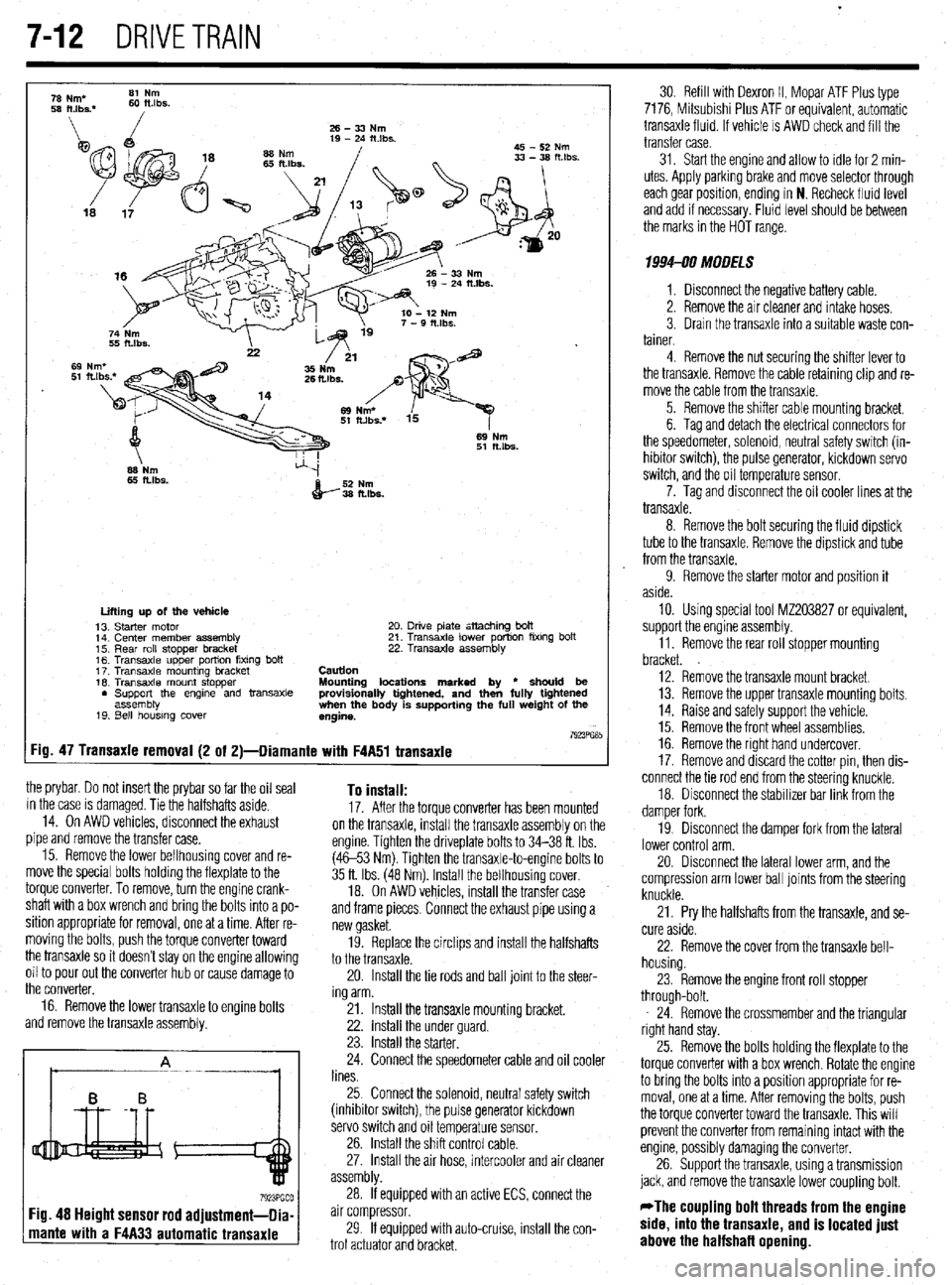
:ig.
the prybar. Do not insert the prybar so far the oil seal
in the case is damaged. Tie the halfshafts aside.
14. On AWD vehicles, disconnect the exhaust
pipe and remove the transfer case.
15. Remove the lower bellhousing cover and re-
move the special bolts holding the flexplate to the
torque converter. To remove, turn the engine crank-
shaft with a box wrench and bring the bolts into a po-
sition appropriate for removal, one at a time. After re-
moving the bolts, push the torque converter toward
the transaxle so it doesn’t stay on the engine allowing
oil to pour out the converter hub or cause damage to
the converter,
16. Remove the lower transaxle to engine bolts
and remove the transaxle assembly. To install: 17. After the torque converter has been mounted
on the transaxle, install the transaxle assembly on the
engine. Tighten the driveplate bolts to 34-38 ft. Ibs.
(4653 Nm). Tighten the transaxle-to-engine bolts to
35 ft. Ibs. (48 Nm). Install the bellhousing cover.
18. On AWD vehicles, install the transfer case
and frame pieces. Connect the exhaust pipe using a
new gasket.
19. Replace the circlips and install the halfshafts
to the transaxle.
20. Install the tie rods and ball joint to the steer-
ing arm.
21. Install the transaxle mounting bracket.
22. install the under guard.
23. Install the starter.
24. Connect the speedometer cable and oil cooler
lines.
25 Connect the solenoid, neutral safety switch
(inhibitor switch), the pulse generator kickdown
servo switch and oil temperature sensor.
26. Install the shift control cable.
27. Install the air hose, intercooler and air cleaner
assembly.
If equipped with an active ECS, connect the
mante with a F4A33 automatic transaxle
30 Refill with Dexron II, Mopar ATF Plus type
7176, Mitsubishi Plus ATF or equivalent, automatic
transaxle fluid. If vehicle is AWD check and fill the
transfer case.
31. Start the engine and allow to idle for 2 min-
utes. Apply parkrng brake and move selector through
each gear posrtion, ending in N. Recheck fluid level
and add if necessary. Fluid level should be between
the marks in the HOT range.
1994-90 MODELS
1. Disconnect the negative battery cable.
2. Remove the air cleaner and intake hoses.
3. Drain the transaxle into a suitable waste con-
tainer.
4. Remove the nut securing the shifter lever to
the transaxle. Remove the cable retaining clip and re-
move the cable from the transaxle.
5. Remove the shifter cable mounting bracket,
6. Tag and detach the electrical connectors for
the speedometer, solenoid, neutral safety switch (in-
hibitor switch), the pulse generator, kickdown servo
switch, and the oil temperature sensor.
7. Tag and disconnect the oil cooler lines at the
transaxle.
8. Remove the bolt securing the fluid dipstick
tube to the transaxle. Remove the dipstrck and tube
from the transaxle.
9. Remove the starter motor and position it
aside.
10. Using special tool MZ203827 or equivalent,
support the engine assembly.
11. Remove the rear roll stopper mounting
bracket.
12. Remove the transaxle mount bracket.
13. Remove the upper transaxle mounting bolts.
14. Raise and safely support the vehicle.
15. Remove the front wheel assemblies.
16. Remove the right hand undercover.
17. Remove and discard the cotter pin, then dis-
connect the tie rod end from the steering knuckle,
18. Disconnect the stabilizer bar link from the
damper fork.
19. Disconnect the damper fork from the lateral
lower control arm.
20. Disconnect the lateral lower arm, and the
compression arm lower ball joints from the steering
knuckle.
21. Pry the halfshafts from the transaxle, and se-
cure aside.
22. Remove the cover from the transaxle bell-
housing.
23. Remove the engine front roll stopper
through-bolt.
24. Remove the crossmember and the triangular
right hand stay.
25. Remove the bolts holding the flexplate to the
torque converter with a box wrench Rotate the engine
to bring the bolts into a position appropriate for re-
moval, one at a time. After removing the bolts, push
the torque converter toward the transaxle. This will
prevent the converter from remaining intact with the
engine, possibly damaging the converter,
26. Support the transaxle, using a transmission
jack, and remove the transaxle lower coupling bolt.
*The coupling bolt threads from the engine
side, into the transaxle, and is located just
above the halfshafl opening.
Page 294 of 408
DRIVETRAiN 7-15
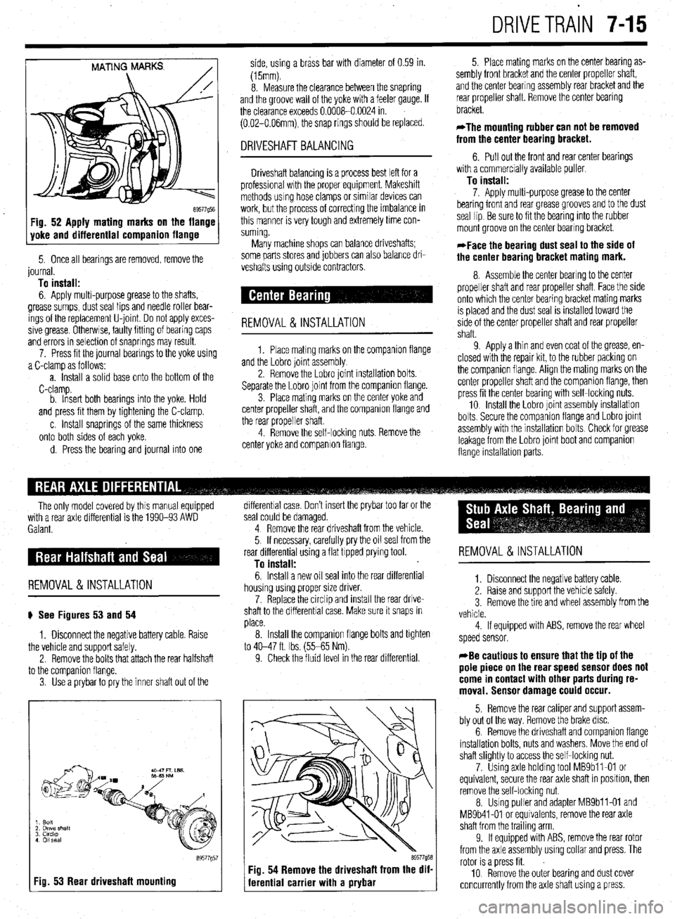
MATING MARKS
/
89577Q5E Fig. 52 Apply mating marks on the flange
yoke and differential companion flange
5. Once all bearings are removed, remove the
journal.
To install:
6. Apply multi-purpose grease to the shafts,
grease sumps, dust seal lips and needle roller bear-
ings of the replacement U-joint Do not apply exces-
sive grease Otherwse, faulty fitting of bearing caps
and errors in selection of snaprings may result.
7. Press fit the journal bearings to the yoke using
a C-clamp as follows:
a. Install a solid base onto the bottom of the
C-clamp.
b. Insert both bearings into the yoke. Hold
and press fit them by tightening the C-clamp.
c. Install snaprings of the same thickness
onto both sides of each yoke.
d. Press the bearing and journal into one side, using a brass bar with diameter of 0.59 in.
(15mm).
8. Measure the clearance between the snapring
and the groove wall of the yoke with a feeler gauge. If
the clearance exceeds 0.0008-0.0024 in.
(0.02-O.O6mm), the snap rings should be replaced.
DRIVESHAFT BALANCING
Driveshaft balancing is a process best left for a
professional wrth the proper equipment. Makeshift
methods using hose clamps or similar devices can
work, but the process of correcting the imbalance in
this manner is very tough and extremely time con-
suming.
Many machine shops can balance driveshafts;
some parts stores and jobbers can also balance dri-
veshafts using outside contractors.
REMOVAL&INSTALLATION
1. Place matmg marks on the companron flange
and the Lobro joint assembly
2. Remove the Lobro joint installation bolts.
Separate the Lobro joint from the companion flange.
3. Place mating marks on the center yoke and
center propeller shaft, and the companion flange and
the rear propeller shaft.
4. Remove the self-locking nuts. Remove the
center yoke and companion flange. 5. Place mating marks on the center bearing as-
sembly front bracket and the center propeller shaft,
and the center bearing assembly rear bracket and the
rear propeller shaft. Remove the center bearing
bracket.
*The mounting rubber can not be removed
from the center bearing bracket.
6. Pull out the front and rear center bearings
with a commercially available puller
To install:
7. Apply multi-purpose grease to the center
bearing front and rear grease grooves and to the dust
seal lip Be sure to fit the bearing into the rubber
mount groove on the center bearing bracket.
*Face the bearing dust seal to the side of
the center bearing bracket mating mark.
8. Assemble the center bearing to the center
propeller shaft and rear propeller shaft. Face the side
onto which the center bearing bracket mating marks
IS placed and the dust seal is installed toward the
side of the center propeller shaft and rear propeller
shaft.
9 Apply a thin and even coat of the grease, en-
closed with the repair kit, to the rubber packing on
the companion flange. Align the mating marks on the
center propeller shaft and the companion flange, then
press fit the center bearing with self-locking nuts.
10 Install the Lobro joint assembly installation
bolts. Secure the companron flange and Lobro joint
assembly with the installation bolts Check for grease
leakage from the Lobro joint boot and companion
flange installabon parts.
The only model covered by this manual equipped
with a rear axle differential is the 1990-93 AWD
Galant.
REMOVAL &INSTALLATION
# See Figures 53 and 54
1. Disconnect the negative battery cable. Raise
the vehicle and support safely.
2. Remove the bolts that attach the rear halfshaft
to the comoanion flanae.
3. Use’a prybar topry the inner shaft out of the
I Fig. 53 Rear driveshaft mounting
89577g5
differential case. Don’t insert the prybar too far or the
seal could be damaged.
4 Remove the rear driveshaft from the vehicle.
5. If necessary, carefully pry the oil seal from the
rear differential using a flat tipped prying tool.
To install:
6. Install a new oil seal into the rear differential
housing using proper size driver.
7. Replace the circlip and install the rear drive-
shaft to the differential case. Make sure it snaps in
place.
8. Install the companion flange bolts and tighten
to 40-47 ft. Ibs. (55-65 Nm).
9. Check the fluid level in the rear differential.
69577958 Fig. 54 Remove the driveshaft from the dif-
ferential carrier with a prybar
REMOVAL &INSTALLATION
1. Disconnect the negative battery cable.
2. Raise and support the vehicle safely.
3 Remove the tire and wheel assembly from the
vehicle.
4 If equipped with ABS, remove the rear wheel
speed sensor.
*Be cautious to ensure that the tip of the
pole piece on the rear speed sensor does not
come in contact with other parts during re-
moval. Sensor damage could occur.
5. Remove the rear caliper and support assem-
bly out of the way. Remove the brake disc.
6. Remove the driveshaft and companion flange
installation bolts, nuts and washers. Move the end of
shaft slightly to access the self-locking nut.
7. Using axle holding tool MBSbll-01 or
equivalent, secure the rear axle shaft in position, then
remove the self-locking nut.
8. Using puller and adapter MBSbll-01 and
MB9b41-01 or equivalents, remove the rear axle
shaft from the trailing arm
9. If equipped with ABS, remove the rear rotor
from the axle assembly using collar and press. The
rotor is a press fit.
10 Remove the outer bearing and dust cover
concurrently from the axle shaft using a press.
Page 307 of 408
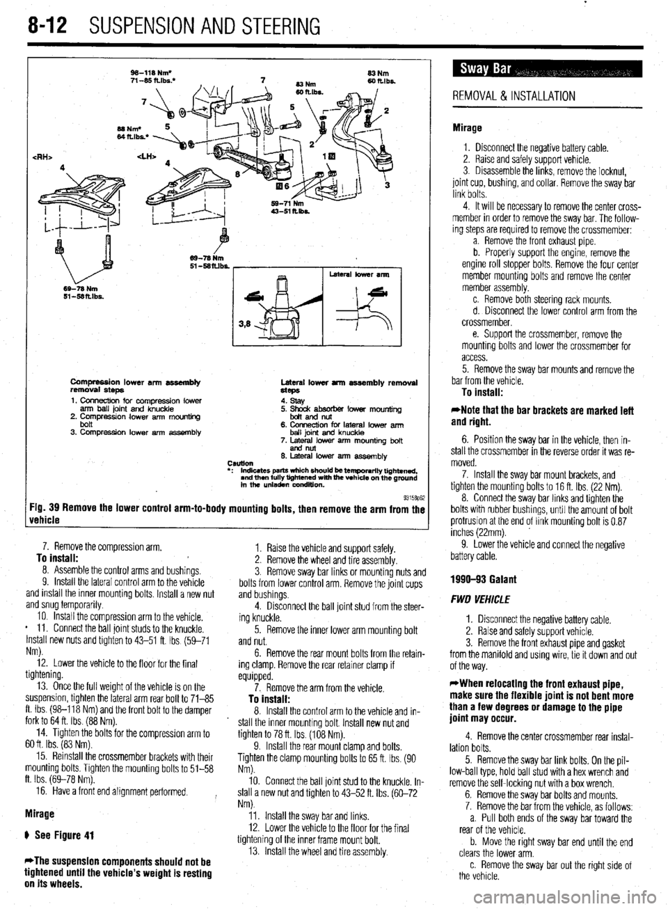
8-12 SUSPENSION AND STEERING
Compression lower an assembly
removal steps Lateral lower arm assembly removal
Hcps
1. Connection for compression lower
arm ball joint and knuckle
2. Compressron lower arm mounting
bolt
3. Compression lower arm assembly 4. stay
5. ~mdtsoorber lower mounting
6. Connection for lateral lower arm
ball joint and knuckle
7. Metal lower arm mounting bolt
end nut
6. Lateral low% arm assemblv
CSUtlOll
l : Indicates parts wfdch should k temporarily tightened,
and then fully tightened with fhe vehicle on the ground
in the unladen wndluon.
93158p62 :ig. 39 Remove the lower control arm-to-body mounting bolts, then remove the arm from the
rehicle
8. Assemole me control arms and bushmgs. 7. Remove the compression arm,
^. To install:
Y. Install the lateral control arm to the vehicle
and install the inner mounting bolts. Install a new nut
and snug temporarily. -. .*.. a.
10. Install the compression arm to the vehicle.
* 11. Connect the ball joint studs to the knuckle.
Install new nuts and tighten to 43-51 ft. Ibs (59-71
Nm).
12. Lower the vehicle to the floor for the final
tightening. 3. Remove sway bar links or mounting nuts and
bolts from lower control arm. Remove the joint cups 1.
and bushings.
4. Raise the vehicle and support safely.
Disconnect the ball joint stud from the steer-
ing knuckle. 2. Remove the wheel and tire assembly
13. Once the full weight of the vehicle is on the
suspension, tighten the lateral arm rear bolt to 71-85
ft. Ibs. (98-118 Nm) and the front bolt to the damper
fork to 64 ft. Ibs. (88 Nm).
14. Tighten the bolts for the compresslon arm to
60 ft. Ibs. (83 Nm).
15. Reinstall the crossmember brackets with their
mounting bolts. Tighten the mounting bolts to 51-58
ft. Ibs. (69-78 Nm).
16. Have a front end alignment performed.
Mirage
ti See Figure 41
*The suspension components should not be
tightened until the vehicle’s weight is resting
on its wheels. 5. Remove the inner lower arm mounting bolt
and nut.
6. Remove the rear mount bolts from the retain-
ing clamp. Remove the rear retainer clamp if
equipped.
7. Remove the arm from the vehicle.
To install:
8. Install the control arm to the vehicle and in-
stall the inner mounting bolt. Install new nut and
tighten to 78 ft. Ibs. (108 Nm).
9. Install the rear mount clamp and bolts.
Tighten the clamp mounting bolts to 65 ft. Ibs. (90
Nm).
10. Connect the ball joint stud to the knuckle. In-
stall a new nut and tighten to 43-52 ft. Ibs. (60-72
Nm).
11. Install the sway bar and links.
12. Lower the vehicle to the floor for the final
tightening of the inner frame mount bolt.
13. Install the wheel and tire assembly.
REMOVAL&INSTALLATION
Mirage
1. Disconnect the negative battery cable.
2. Raise and safely support vehicle.
3. Disassemble the links, remove the locknut,
joint cup, bushing, and collar. Remove the sway bar
link bolts.
4. It will be necessary to remove the center cross-
member in order to remove the sway bar. The follow-
ing steps are required to remove the crossmember:
a. Remove the front exhaust pipe
b. Properly support the engine, remove the
engine roll stopper bolts. Remove the four center
member mounting bolts and remove the center
member assembly.
c. Remove both steering rack mounts.
d. Disconnect the lower control arm from the
crossmember,
e. Support the crossmember, remove the
mounting bolts and lower the crossmember for
access.
5. Remove the sway bar mounts and remove the
bar from the vehicle.
To install:
*Note that the bar brackets are marked left
and right.
6. Position the sway bar in the vehicle, then in-
stall the crossmember in the reverse order it was re-
moved.
7. Install the sway bar mount brackets, and
tighten the mounting bolts to 16 ft. Ibs. (22 Nm).
8. Connect the sway bar links and tighten the
bolts with rubber bushings, until the amount of bolt
protrusion at the end of link mounting bolt is 0.87
inches (22mm).
9. Lower the vehicle and connect the negative
battery cable.
1990-93 Galant
FWD VEHICLE
1. Disconnect the negative battery cable.
2. Raise and safely support vehicle.
3. Remove the front exhaust pipe and gasket
from the manifold and using wire, tie it down and out
of the way.
WWhen relocating the front exhaust pipe,
make sure the flexible joint is not bent more
than a few degrees or damage to the pipe
joint may occur.
4. Remove the center crossmember rear instal-
lation bolts.
5. Remove the sway bar link bolts. On the pil-
low-ball type, hold ball stud with a hex wrench and
remove the self-locking nut with a box wrench.
6. Remove the sway bar bolts and mounts.
7. Remove the bar from the vehicle, as follows:
a. Pull both ends of the sway bar toward the
rear of the vehicle.
b. Move the right sway bar end until the end
clears the lower arm.
c. Remove the sway bar out the right side of
the vehicle.
Page 360 of 408
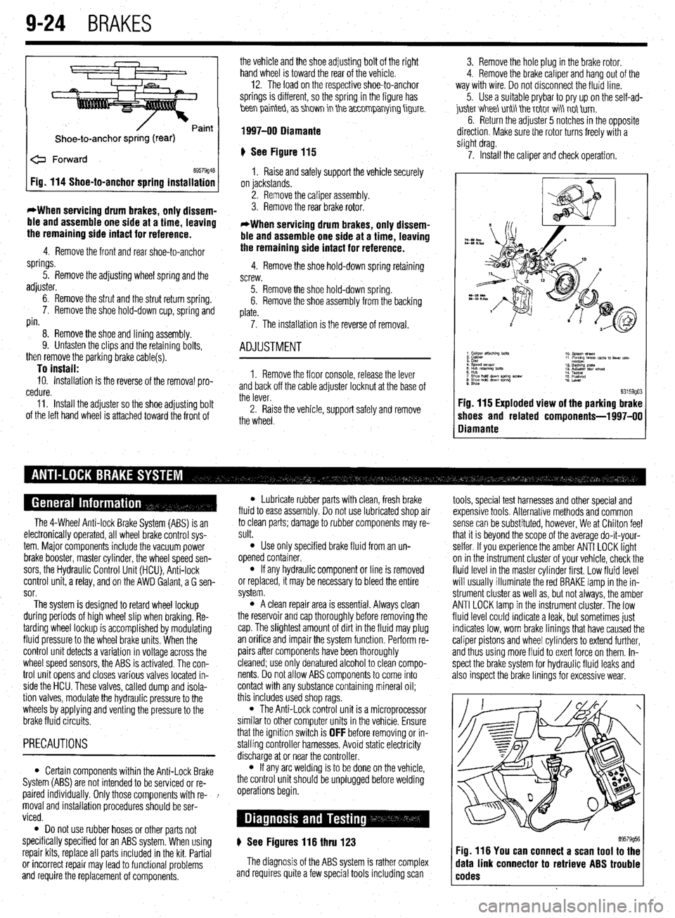
9-24 BRAKES
Shoe-to-anchor spring (rear)
e Forward
69579946 Fig. 114 Shoe-to-anchor spring installation
*When servicing drum
brakes, only dissem-
ble and assemble one side at a time, leaving
the remaining side intact for reference.
4. Remove the front and rear shoe-to-anchor
springs.
5. Remove the adjusting wheel spring and the
adjuster.
6. Remove the strut and the strut return spring.
7. Remove the shoe hold-down cup, spring and
pin.
8. Remove the shoe and lining assembly.
9. Unfasten the clips and the retaining bolts,
then remove the parking brake cable(s).
To install: 10. Installation is the reverse of the removal pro-
cedure.
11. Install the adjuster so the shoe adjusting bolt
of the left hand wheel is attached toward the front of the vehicle and the shoe adjusting bolt of the right
hand wheel is toward the rear of the vehicle. -
12. The load on the respective shoe-to-anchor
springs is different, so the spring in the figure has
hen painteb, a> shm in the a~~0mparrying figure.
1997-00 Diamante
‘) See Figure 115
1. Raise and safely support the vehicle securely
on jackstands.
2. Remove the caliper assembly.
3. Remove the rear brake rotor.
*When servicing drum brakes, only dissem-
ble and assemble one side at a time, leaving
the remaining side intact for reference.
4. Remove the shoe hold-down spring retaining
screw.
5. Remove the shoe hold-down spring.
6. Remove the shoe assembly from the backing
plate.
7. The installation is the reverse of removal.
ADJUSTMENT
1. Remove the floor console, release the lever
and back off the cable adjuster locknut at the base of
the lever.
2. Raise the vehicle, support safely and remove
the wheel. 3. Remove the hole plug in the brake rotor.
4. Remove the brake caliper and hang out of the
way with wire. Do not disconnect the fluid line.
5. Use a suitable prybar to pry up on the self-ad-
juskr V&I&I unti tie T&IT wi\ not tirn.
6. Return the adjuster 5 notches in the opposite
direction. Make sure the rotor turns freely with a
slight drag.
7. Install the caliper and check operation.
9. Shoe 93159go3 Fig. 115 Exploded view of the parking brake
shoes and related components-l 997-00
Diamante
The 4-Wheel Anti-lock Brake System (ABS) is an
electronically operated, all wheel brake control sys-
tem. Major components include the vacuum power
brake booster, master cylinder, the wheel speed sen-
sors, the Hydraulic Control Unit (HCU), Anti-lock
control unit, a relay, and on the AWD Galant, a G sen-
sor.
The system is designed to retard wheel lockup
during periods of high wheel slip when braking. Re-
tarding wheel lockup is accomplished by modulating
fluid pressure to the wheel brake units. When the
control unit detects a variation in voltage across the
wheel speed sensors, the ABS is activated. The con-
trol unit opens and closes various valves located in-
side the HCU. These valves, called dump and isola-
tion valves, modulate the hydraulic pressure to the
wheels by applying and venting the pressure to the
brake fluid circuits.
PRECAUTIONS
l Certain components within the Anti-Lock Brake
System (ABS) are not intended to be serviced or re-
paired individually. Only those components with re- !
moval and installation procedures should be ser-
viced.
0 Do not use rubber hoses or other parts not
specifically specified for an ABS system. When using
repair kits, replace all parts included in the kit. Partial
or incorrect repair may lead to functional problems
and require the replacement of components.
l Lubricate rubber parts with clean, fresh brake
fluid to ease assembly. Do not use lubricated shop air
to clean parts; damage to rubber components may re-
sult.
l Use only specified brake fluid from an un-
opened container.
l If any hydraulic component or line is removed
or replaced, it may be necessary to bleed the entire
system.
l A clean repair area is essential. Always clean
the reservoir and cap thoroughly before removing the
cap. The slightest amount of dirt in the fluid may plug
an orifice and impair the system function. Perform re-
pairs after components have been thoroughly
cleaned; use only denatured alcohol to clean compo-
nents. Do not allow ABS components to come into
contact with any substance containing mineral oil;
this includes used shop rags.
l The Anti-Lock control unit is a microprocessor
similar to other computer units in the vehicle. Ensure
that the ignition switch is
OFF before removing or in-
stalling controller harnesses. Avoid static electricity
discharge at or near the controller.
l If any arc welding is to be done on the vehicle,
the control unit should be unplugged before welding
operations begin.
) See Figures 116 thru 123
The diagnosis of the ABS system is rather complex
and requires quite a few special tools including scan tools, special test harnesses and other special and
expensive tools. Alternative methods and common
sense can be substituted, however, We at Chilton feel
that it is beyond the scope of the average do-it-your-
selfer. If you experience the amber ANTI LOCK light
on in the instrument cluster of your vehicle, check the
fluid level in the master cylinder first. Low fluid level
will usually illuminate the red BRAKE lamp in the in-
strument cluster as well as, but not always, the amber
ANTI LOCK lamp in the instrument cluster. The low
fluid level could indicate a leak, but sometimes just
indicates low, worn brake linings that have caused the
caliper pistons and wheel cylinders to extend further,
and thus using more fluid to exert force on them. In-
spect the brake system for hydraulic fluid leaks and
also inspect the brake linings for excessive wear.
89579956 Fig. 116 You can connect a scan tool to the
data link connector to retrieve ABS trouble
codes
Page 380 of 408
.
1042 BODYANDTRIM
P
I. i%lllUVt: LIE UUUI yldbb Uy lllllll!J It up ana out ot me ease, wnicn IS glueo onto tne wmasnlela. 1 ne
of the door.
installation is the reverse of the removal procedure. If
8. Remove the installation bolts holding the
the mirror base falls off of the windshield it can be in-
regulator to the door.
stalled as follows:
I
9. If equipped with electric windows discnnnad
1. Scrape the base mounting area with a razor
LllC vvllllly L” t,te Wlll”“W lll”l”l.
blade to remove the old adhesive.
I 10. Remove the regulator through the access hole
2. Thoroughly clean the base mounting ara.
’ in the door.
3. Obtain a mirror adhesive kit. Apply the clean-
To install:
ing compound to the windshield in the area that the
11. When reinstalling the regulator, apply a light
base is to be mounted. Allow to dry.
coat of multipurpose grease to the moving parts.
4. Apply the adhesive to both the base plate and
12. Install the regulator and tighten the bolts fin-
the windshield. Install the base to the glass. Hold in
ger-tight.
position until the adhesive has a chance to set. Make
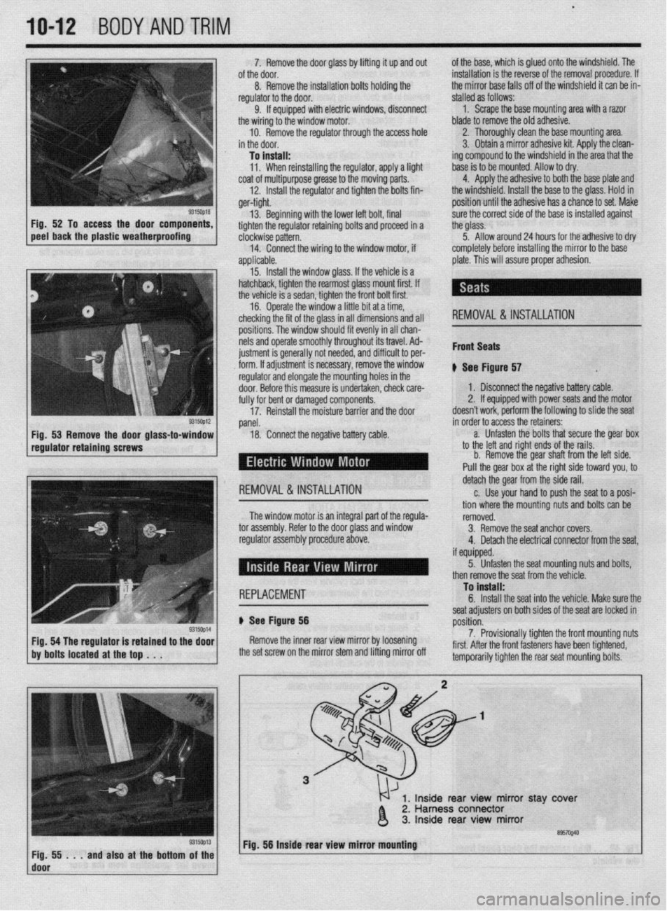
5315oQ18 Fig. 52 To access the door components,
peel back the plastic weatherproofing 13. Beginning with the lower left bolt, final
tighten the regulator retaining bolts and p
clockwise pattern.
14.
applic
+r roceed in a
Connect the wiring to the window motor, if
able.
Install the window glass. If the vehicle is a
lack, tighten the rearmost glass mount first. If
hicle is a sedan, tighten the front bolt first.
.
13. hatcht
the ve’
16. Uperate the window a little bit at a time,
checking the fit of the glass in all dimensions and all
positions. The window should fit evenly in all chan-
nels and operate smoothly throughout its travel. Ad-
ius~ment is rener;IIIv not needed. and diffirlllf +n nor- . ._ ~ _.._. - ., _.
___.-, - - _ lll”“ll I” pm
i&h. If adiustment is necessarv, remove thp win&N I..” . . . ..“1.. regulator and elongate the mointing holes in the
door. Before this measure is undertaken, check care-
fully for bent or damaged components.
17. Reinstall the moisture barrier and the door sure the correct side of the base is installed against
the glass.
5. Allow around 24 hours for the adhesive to dry
completely before installing the mirror to the base
plate. This will assure proper adhesion.
REMOVAL & INSTALLATION
Front Seats
* err ei
I ovv rlgure 57 .
1, Disconnect the negative battery cable.
2. If equipped with power seats and the motor
doesn’t work, perform the following to slide the seat
panel.
18. Conned the negative battery Cable. in order to acdess the retainers:
-
a. Unfasten the bolts that secure the gear box
to the left and right ends of the rails.
b. Remove the gear shaft from the left side.
Pull the gear box at the right side toward you, to
I REMOVAL & INSTALLATION detach the gear from the side rail.
c. Use your hand to push the seat to a posi-
tion where the mounting nuts and bolts can be
The window motor is an integral part nf the renlrla-
romnvPrl
-’ .“- ‘-J-.- tor assembly. Refer to the door Glass and window
regulator assembly procedure above. IYII,“.““. 3. Remove the seat anchor covers.
4. Detach the electrical connector from the seat,
if m~innd I I, “y”y~Y”. 5. Unfasten the seat mountina nuts and bolts.
1 REPLACEMENT To install:
c
b Ser f Floure 56
Yap- ~~
Remove the inner rear view mirror by loosening
the set screw on the mirror stem and lifting mirror off seat adjusters on both sides of the seat are locked in
rmritinn p”3111”ll.
7. Provisionally tighten the front mounting nuts
first. After the front fasteners have been tightened,
tomnnr.,rilw tinhton thn co.-ar co.,+ m qunting bolts. then remove the seat from the vehicle.
1, Inside rear view mirror stay ‘cover
2. Harness connector
3. Inside rear view mirror
’ ~;f!i!i...andalsoatthebottom~~~~ Fig. 56 Inside rear view mirror mbuntlng
I
Page 407 of 408
MASTER INDEX 11-25 -
REAROUTPUTSHAFTSEAL 7-14
TESTING 6-5
REMOVAL & INSTALLATION 7-14
' THERMOSTAT 3-7
REAR SUSPENSION 8-18 REMOVAL & INSTALLATION 3-7
REAR WINDOW WIPER SWITCH 6-19 THROTTLE BODY 5-3
REMOVAL&INSTALLATION 6-19 REMOVAL & INSTALLATION 5-3
REARDRlVEAXLE(AWDGALANTONLY) l-38
THROTTLEPOSITIONSENSOR 4-13
DRAIN &REFILL 1-38
OPERATION 4-13
FLUIDRECOMMENDATIONS 1-38 , REMOVAL&INSTALLATION 4-13
LEVELCHECK l-38
TESTING 4-13
REGULATOR 2-10 TIMING COVERAND BELT 3-36
REMOVAL&INSTALLATION 2-10
INSPECTION 3-48
RELIEVING FUELSYSTEM PRESSURE 5-3 REMOVAL & INSTALLATION 3-36
ROCKERARM(VALVE)COVER 3-1
TIMING BELTS l-20
REMOVAL & INSTALLATION 3-1
INSPECTION I-20
ROCKER ARM/SHAFTS 3-4
TIRESANDWHEELS I-30
REMOVAL & INSTALLATION 3-4
CAREOFSPECIALWHEELS l-32
ROUTINE MAINTENANCE AND TUNE-UP 1-14 INFLATION & INSPECTION I-31
SEATS IO-IO
TIRE DESIGN I-31
REMOVAL&INSTALLATION IO-IO TIRE ROTATION I-30
SENDING UNITS 2-11
TIRESTORAGE I-31
SERIAL NUMBER IDENTIFICATION l-10
TONE (EXCITER) RING 9-29
SERVICING YOUR VEHICLE SAFELY I-4
REMOVAL & INSTALLATION 9-29
SHOCKABSORBERAND COILSPRING 8-8
TOOLS AND EQUIPMENT 1-2
OVERHAUL 8-9
TORQUE 1-7
REMOVAL&INSTALLATION 8-8 TORQUEANGLEMETERS l-9
SIGNAL AND MARKER LIGHTS 6-21
TORQUEWRENCHES l-7
REMOVAL & INSTALLATION 6-21
TOWING THE VEHICLE 1-44
SPARKPLUG WIRES 1-24
TRAINING ARM 8-24
REMOVAL&INSTALLATION 1-24
REMOVAL & INSTALLATION 8-24
TESTING 1-24
TRANSAXLEIDENTIFICATION I-10
SPARKPLUGS l-22
TRANSFER CASE ASSEMBLY 7-14
INSPECTION &GAPPING l-23
REMOVAL & INSTALLATION 7-14
REMOVAL&INSTALLATION 1-22
TRANSFER CASE 7-14
SPARKPLUGHEATRANGE 1-22
TRANSFERCASE(AWD GALANT ONLY) 1-38
SPEAKERS 6-14
DRAIN &REFILL 1-38
REMOVAL & INSTALLATION 6-14
FLUIDRECOMMENDATIONS 1-38
SPECIALTOOLS 1-4
LEVELCHECK 1-38
SPEED SENSORS 9-28
TRANSFERCASE(AWDGALANTONLY) I-10
REMOVAL & INSTALLATION 9-28
TROUBLESHOOTING ELECTRICALSYSTEMS 6-5
STANDARDANDMETRIC MEASUREMENTS l-9
OPEN CIRCUITS 6-5
STARTER 2-10
RESISTANCE 6-8
REMOVAL&INSTALLATION 2-11
SHORT CIRCUITS 6-6
TESTING 2-10
VOLTAGEDROP 6-6
STARTING SYSTEM 2-10
VOLTAGE 6-6
STEERING LINKAGE 8-30
TRUNK LID IO-3
REMOVAL &INSTALLATION 8-30
ALIGNMENT IO-3
STEERING WHEEL 8-27
REMOVAL & INSTALLATION IO-3
REMOVAL &INSTALLATION 8-27
TURBOCHARGER 3-17
STEERING 8-27
REMOVAL & INSTALLATION 3-17
STRUT AND COIL SPRING
8-21
UNDERSTANDING AND TROUBLESHOOTING ELECTRICAL
OVERHAUL 8-22
SYSTEMS 6-2
REMOVAL & INSTALLATION 8-21
UNDERSTANDINGTHEAUTOMATICTRANSAXLE 7-10
STUBAXLESHAFT,BEARlNG AND SEAL 7-15
REMOVAL & INSTALLATION 7-10
REMOVAL&INSTALLATION 7-15
UNDERSTANDINGTHECLUTCH 7-7
SWAY BAR 8-12
ADJUSTMENTS 7-8
REMOVAL 8, INSTALLATION 8-12
REMOVAL&INSTALLATION 7-7
SWAY BAR 8-25
UNDERSTANDINGTHE MANUALTRANSAXLE 7-2
REMOVAL&INSTALLATION 8-25
SHIFT LINKAGE 7-2
TAILGATE/HATCH HANDLE lo-19
UPPER BALLJOINT 8-9
REMOVAL &INSTALLATION lo-10
INSPECTION 8-9
TAILGATE IO-3
REMOVAL &INSTALLATION 8-9
ALIGNMENT IO-3 i'
UPPER CONTROLARM 8-10
REMOVAL & INSTALLATION IO-3
REMOVAL & INSTALLATION 8-10
TANKASSEMBLY 5-10
UPPER CONTROL ARMS 8-22
REMOVAL&INSTALLATION 5-10
REMOVAL & INSTALLATION 8-22
TEST EQUIPMENT 6-4
VACUUM DIAGRAMS 4-36
JUMPER WIRES 6-4
VALVE LASH 1-27
MULTIMETERS 6-5
ADJUSTMENT 1-27
TEST LIGHTS 6-4
VEHICLE IDENTIFICATION NUMBER I-10