1900 MITSUBISHI DIAMANTE alternator
[x] Cancel search: alternatorPage 17 of 408
l
1-18 GENERALINFORMATIONAND MAINTENANCE
the clamps and remove the cables, negative cable
first. On batteries with posts on top, the use of a
puller specially made for this purpose is recom-
mended. These are inexoensive and available in most alternator or turn the adjusting bolt to adjust belt ten-
sion. Once the desired value is reached, secure the
bolt or locknut and recheck tension.
d”t” lJdlL> X”lt;>. 31°C LtXlllllldl lJdllt2)’ MLJIC, dlt’ X- cured with a small bolt. ST& I REMOVAL &INSTALLATION
Clean the cable clamps and the battery terminal I
with a wire brush, until all corrosion, grease, etc., is
removed and the metal is shinv. It is esneciallv imnnr-
tant to c
knife is useful nere), since a smart
material or oxidation there will pre Clean the cable clamps and the battery terminal
with a wire brush, until all corrosion, grease, etc., is
removed and the metal is shiny. It is especially impor-
tant to clean the inside of the clamp thoroughly (an old
knife is useful here), since a small deposit of foreign
material or oxidation there will prevent a sound electri-
cal connection and inhibit either starting or charging.
Special tools are available for cleaning these parts,
one type for conventional top post batteries and an-
other type for side terminal batteries. It is also a good
idea to apply some dielectric grease to the terminal, as
this will aid in the prevention of corrosion,
After the clamps and terminals are clean, reinstall
the cables, negative cable last; DO NOT hammer the
clamps onto battery posts. Tighten the clamps se-
curely, but do not distort them. Give the clamps and
terminals a thin external coating of grease after in-
stallation, to retard corrosion.
Check the cables at the same time that the terminals
are cleaned. If the cable insulation is cracked or bro-
ken, or if the ends are frayed, the cable should be re-
placed with a new cable of the same length and gauge.
CHARGING
the cables, negative cable last; DO NOT hammer the
curely, but do not distort them. Give the clamps and
terminals a thin external coating of grease after in-
stallation, to retard corrosion.
Check the cables at the same time that the terminals
are cleaned. If the cable insulation is cracked or bro-
ken, or if the ends are frayed, the cable should be re-
placed with a new cable of the same length and aauae.
CHARGING
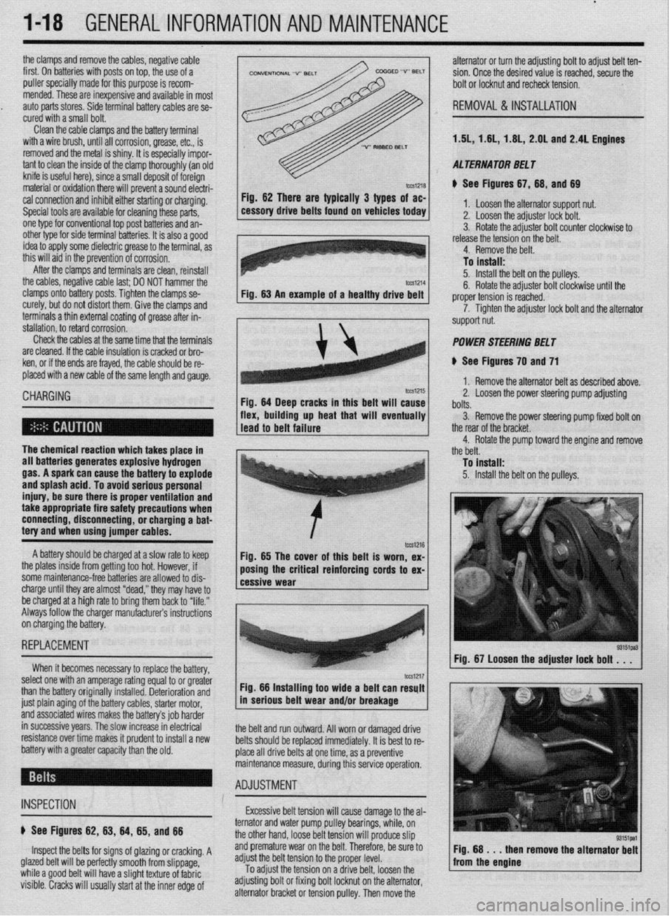
Fig. 62 mere are typically 3 types of ac-
cessory drive belts found on vehicles today 1. Loosen the alternator support nut.
2. Loosen the adjuster lock bolt.
3. Rotate the adjuster bolt counter clockwise to
I .I , . . . * . .
I Tn i”et*ll* Fig. 62 There are typically 3 types of ac-
Fig. 64 Deep cracks in this belt will cause
flex, building up heat that will eventually 11, 1.8L, 2.OL and 2.4L Engines
cal connection and inhibit either starting or charging.
Special tools are available for cleaning these parts,
one type for conventional top post batteries and an-
other type for side terminal batterin, I+ if QI@* 3 nnnd
idea to apply some dielectric grr
this will aid in the prevention of ,,vIIuaIUII.
After the clamps and terminals are clean, reinstall 1.5L, 1.6
AL TERNA TOR BE1 T
e See Figures 67,68, and 69
1. Loosen the alternator support nut.
2. Loosen the adjuster lock bolt.
3. Rotate the adjuster bolt counter clockwise to
release the tension on the belt.
4. Remove the belt.
To install:
5. Install the belt on the pulleys.
6. Rotate the adjuster bolt clockwise until the
proper tension is reached.
7. Tighten the adjuster lock bolt and the alternator
support nut.
POWER STEERING BELT
8 See Figures 70 and 71
1. Remove the alternator belt as described above.
2. Loosen the power steering pump adjusting
bolts.
3. Remove the power steering oumo fixed bolt on
R Rntatn the cxiillrtm hnit A&+,& until the r -r- .- .- ._.. ._ .______
7. Tighten the adjuster lock bolt and the alternator
support nut.
POWER STEERING BELT
1 ..“‘.I ““..Y...Y up II”“. ..IU. ..m.*
1 lead to belt failure V.
I
I
The chemical reaction which takes place in - 1 the rear of the bracket.
4. Rotate the pump toward the engine and remove
the belt.
all batteries generates explosive hydrogen
gas. A spark can cause the battery to explode
and splash acid. To avoid serious personal
injury, be sure there is proper ventilation and
take appropriate fire safety precautions when
connecting, disconnecting, or charging a bat-
tery and when using jumper cables. To fnstall:
5. Install the belt on the pulleys.
A battery should be charged at a slow rate to keep
the plates inside from getting too hot. However, if
some maintenance-free batteries are allowed to dis-
charge until they are almost “dead,” they may have to
be charged at a high rate to bring them back to “life.”
Always follow the charger manufacturers instructions
on charging the battery. 85 The cover of this belt ex-
Fig. is worn,
REPLACEMENT
When it becomes necessary to reolace thn haeoN
‘” yyL’“‘J’ I or oreMer
select one with an amperage rating equal tc .
a ----
than the battery originally installed. Deterioration and
just plain aging of the battery cables, starter motor,
and associated wires makes the battery’s job harder
in successive years. The slow increase in electrical
resistance over time makes it prudent to install a new
battery with a greater capacity than the old. 1 Fig. 67 Loosen the adjuster lock bolt . . .
I ‘-
I -. -_ tm1217 Fig. 66 Installing too wide a belt can resylt
in serious belt wear and/or breakage
the belt and run outward. All worn or damaged drive
belts should be replaced immediately. It is best to re-
place all drive belts at one time, as a preventive
uring this service operation. maintenance measure, d
- ADJUSTMENT : *
INSPECTION Excessive belt tension will cause damage to the al-
e See Figures 62, 83, 64, 65, and 88
Inspect the belts for signs of glazing or cracking. A
glazed belt will be perfectly smooth from slippage,
while a good belt will have a slight texture of fabric
visible. Cracks will usually start at the inner edge of pulley bearings, while, on
It tension will
Droduce slin ternator and water pump
the other hand, loose be
r ------ r
and premature wear on the belt. Therefore, be sure to
adjust the belt tension to the proper level.
To
adjust the tension ’ ’ ’ ” ’ ‘* adjusting bolt or fixing b
alternator bracket or tens on a onve Den. loosen me I Fig. 68 . . . then
from the engine remove the alternator
bolt locknut on the alternator,
iion pulley. Then move the
Page 18 of 408
GENERAL INFORMATION AND MAlNTENANdE l-19
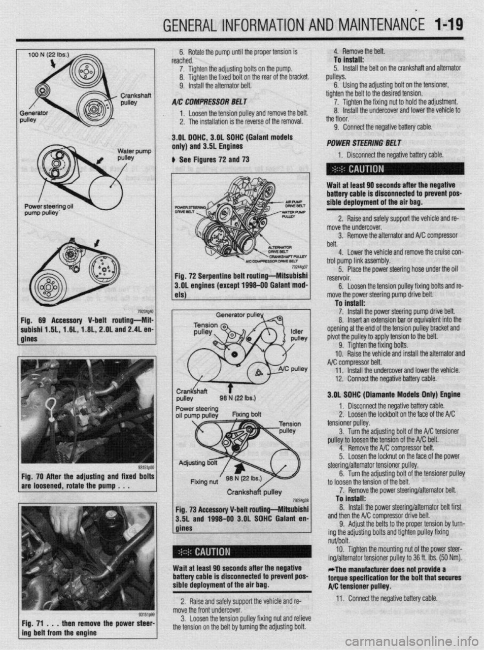
792UQ4 Fig. 69 Accessory V-belt routing-Mii
subishf 1.6L, 1.6L,-1.6L, 2.OL and 2.4L en
gines
33151PM Fig. 70 After the adjusting and fixed bolt!
are loosened, rotate the pump . . .
/ F$71t immtl$mm&a the power ::: 6. Rotate the pump until the proper tension is
reached.
7. Tighten the adjusting bolts on the pump.
8. Tighten the fixed bolt on the rear of the bracket.
9. Install the alternator belt.
A/r: COMPRESSOIl BEL f
1. Loosen the tension oullev and remove the belt.
2. The installation is the reverse of the removal.
.3.gL DGHC, 3.OL SOHC (Gaiant models
only) and 3.5L Engines 4. Remove the belt.
To install:
5. Install the belt on the crankshaft and alternator
pulleys.
6. Using the adjusting bolt on the tensioner,
tighten the belt to the desired tension.
7. Tighten the fixing nut to hold the adjustment.
8. Install the undercover and lower the vehicle to
_,
the tloor.
9. Connect the negative battery cable.
POWER SliEERlNG BEL f
6 See Figures 72 and 73 1. Disconnect the neaative batteN cah+P
-I
Wait at least 60 seconds after the negative
battery cable is disconnected to prevent poS-
sibie deployment of the air bag.
2. Raise and safely support the vehicle and re-
mob re the undercover.
3. Remove the alternator and NC compressor
belt.
4. Lower the vehicle and remove the cruise con-
trol oumn link iW%mblV. 79244Q.37
-- I-- r ---- - _I
Fig. 72 Serpentine belt routing-Mitsubishi 5. Place the power steering hose under the oil
reservoir.
3.OL engines (except 1696-00 Galant mod-
6.
Loosen the tension pulley fixing bolts and re-
els)
Generator pulP
1 move the power steering pump drive belt.
To install:
1 7. install the Dower steerina oumu r+r+v~ hp++
8. Insert an extension bar &eoufvaik;;t”f;;id‘he
opening at the end of the tension pulley bracket and
pivot the pulley to apply tension to the belt.
9. Tighten the fixing bolts.
10. Raise the vehicle and install the alternator and
compressor belt.
Il. Install the undercover and lower +hfi vph+r+p
.I,., .VII.“.Y.
12. Connect the negative battery cable.
I 3.OL SGHC (Diamante Models Onivl Enotne
I ,r ” 1. Disconnect the negative battery cable.
2.’ Loosen the lockbolt on the face nf the A/C _ __.- tensioner pulley.
3
Turn the adiustina bolt of the A/C +fincrnner
pulley to loosen the tension of the A/C belt.
4. Remove the A/C compressor belt.
5.
Loosen the locknut on the face of the power
to loosen the tc
7. Remov
Fig. 73 Accessory V-belt routing-Mitsubishi
3.5L and 1996-00 3.OL SOHC Galant en-
gines steering/alternator tensloner pulley.
6. Turn the adjusting bolt of the tensioner pulley
msion of the belt.
‘e the power steering/alternator belt.
To install:
8. Install the power steering/alternator belt first
.* .* . ,^
ssor drive belt. ana tnen tne A/ti compre:
9. Adjust the belts t+
ing the adjusting bolts anu
II~IIWII pueey tlxmg I the proper tension by turn-
A.:-L I-..-.. I,^, .’
nut/bolt.
10. Tighten the mounting nut of the power steer-
ing/alternator tensioner pulley to 36 ft. Ibs. (50 Nm).
Wait at least 60 seconds after the negative
battery cable is disconnected to prevent pos-
sible deployment of the air bag. -The manufacturer does not provide a
torque specification for the bolt that secures
A/C tensioner pulley.
2. Raise and safely support the vehicle and re- 11. Connect the negative battery cable.
move the front undercover.
3. Loosen the tension pulley fixing nut and relieve
the tension on the belt by turning the adjusting bolt.
Page 45 of 408
.
I-46 GENERALINFORMATIONAND MAINTENANCE
2. Pull the jumping vehicle (with the good bat-
tery) into a position so the jumper cables can reach
the dead battery and that vehicle’s engine. Make sure
that the vehicles do NOT touch.
3. Place the transmissions/transaxles of both ve-
hicles in Neutral (MT) or P (AT), as applicable, then
firmly set their parking brakes.
*ff necessary for safety reasons, the hazard
lights on both vehicles may be operated
throughout the entire procedure without sig-
nificantiy increasing the diff icuity of jumping
the dead battery.
4. Turn all lights and accessories OFF on both
vehicles. Make sure the ignition switches on both ve-
hicles are turned to the OFF position.
5. Cover the battery cell caps with a rag, but do
not cover the terminals.
6. Make sure the terminals on both batteries are
clean and free of corrosion or proper electrical con-
nection will be impeded. If necessary, clean the bat-
tery terminals before proceeding.
7. Identify the positive (+) and negative (-) termi-
nals on both batteries.
8. Connect the first jumper cable to the positive
(t) terminal of the dead battery, then connect the
other end of that cable to the positive (t) terminal of
the booster (good) battery.
9. Connect one end of the other jumper cable to
the negative (−) terminal on the booster bat-
tery and the final cable clamp to an engine bolt head,
alternator bracket or other solid, metallic point on the
engine with the dead battery. Try to pick a ground on
the engine that is positioned away from the battery in
order to minimize the possibility of the 2 clamps
touching should one loosen during the procedure.
DO NOT connect this clamp to the negative (-) termi-
nal of the bad battery. cable on the donor battery. Disconnect the positive
cable from the donor battery and finally, disconnect
the positive cable from the formerly dead battery. Be
careful when disconnecting the cables from the posi-
tive terminals not to allow the alligator clips to touch
any metal on either vehicle or a short and sparks will
occur.
I
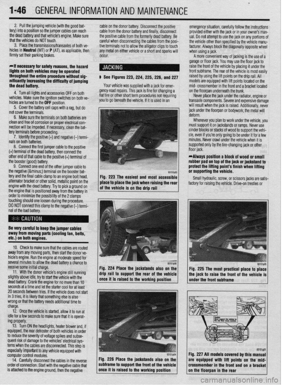
$ See Figures 223,224, 225,226, and 227
Your vehicle was supplied with a jack for emer-
gency road repairs. This jack is fine for changing a
flat tire or other short term procedures not requiring
you to go beneath the vehicle. If it is used in an emergency situation, carefully follow the instructions
provided either with the jack or in your owners man-
ual. Do not attempt to use the jack on any portions of
the vehicle other than specified by the vehicle manu-
facturer. Always block the diagonally opposite wheel
when using a jack.
A more convenient way of jacking is the use of a
garage or floor jack. You may use the floor jack to
raise the front of the vehicle by placing it under the
front subframe. The rear of the vehicle is most easily
raised by using the lift points on the drip rail. All
models are equipped with lift points located on the
mid- crossmember in the front and a bracket located
on the floorpan underneath the trunk.
Never place the jack under the radiator, engine or
transaxle components. Severe and expensive damage
will result when the jack is raised. Additionally, never
jack under the floorpan or
bodywork; the
metal will
Whenever you plan to work under the vehicle, you
must support it on jackstands or ramps. Never use
cinder blocks or stacks of wood to support the vehi-
cle, even if you’re only going to be under it for a few
minutes. Never crawl under the vehicle when it is
supported only by the tire-changing jack or other
*Always position a block of wood or small
rubber pad on top of the jack or jackstand to
protect the lifting point’s finish when lifting
or supporting the vehicle.
Small hydraulic, screw, or scissors jacks are satis-
factory for raising the vehicle. Drive-on trestles or
Be very careful to keep the jumper cables
away from moving parts (cooling fan, belts,
etc.) on both engines.
10. Check to make sure that the cables are routed
away from any moving parts, then start the donor ve-
hicle’s engine. Run the engine at moderate speed for
several minutes to allow the dead battery a chance to
receive some initial charge.
11. With the donor vehicle’s engine still running
slightly above idle, try to start the vehicle with the
dead battery. Crank the engine for no more than 10 &stands also on the
Fig. 225 The most practical place to place
front of the vehicle is
seconds at a time and let the starter cool for at least
20 seconds between tries. If the vehicle does not start
in 3 tries, it is likely thatsomething else is also
wrong or that the battery needs additional time to
charge.
12. Once the vehicle is started, allow it to run at
idle for a few seconds to make sure that it is operat-
ing properly.
13. Turn ON the headlights, heater blower and, if
equipped, the rear defroster of both vehicles in order
to reduce the severity of voltage spikes and subse-
quent risk of damage to the vehicles’ electrical sys-
tems when the cables are disconnected. This step is
especially important to any vehicle equipped with
computer control modules.
14. Carefully disconnect the cables in the’reverse
order of connection. Start with the negative cable that
is attached to the engine ground, then the negative Fig. 226 Place the jackstands also
subframe to support the front of the Fig. 227 All models covered by this
are equipped with lift points on t
crossmember in the front and on a
Page 48 of 408
DISTRIBUTOR IGNITION SYSTEM
GENERALINFORMATION 2-2
DIAGNOSISANDTESTING 2-2
SECONDARYSPARKTEST 2-2
CYLINDERDROPTEST 2-2
ADJUSTMENTS 2-3
IGNITION COIL 2-3
TESTING 2-3
REMOVAL&INSTALLATION 2-3
POWERTRANSISTOR
(Ignition Module) 2-4
REMOVAL&INSTALLATION 2-4
DISTRIBUTOR 2-4
REMOVAL&INSTALLATION 2-4 2-2
INSTALLATION 2-4
CRANKSHAFTANDCAMSHAFTPOSITION
SENSORS 2-5
DISTRIBUTORLESS IGNITION
SYSTEM 2-5
GENERALINFORMATION 2-5
DIAGNOSISANDTESTING 2-5
ADJUSTMENTS 2-5
IGNITION COIL(s) 2-5
TESTING 2-5
REMOVAL&INSTALLATION 2-6
POWERTRANSISTOR
(IGNITION MODULE) 2-7
REMOVAL&INSTALLATION 2-7
CRANKSHAFTANDCAMSHAFTPOSITION
SENSORS 2-7
FIRING ORDERS 2-7
CHARGING SYSTEM 2-8
GENERALINFORMATION 2-8
ALTERNATORPRECAUTIONS 2-8
ALTERNATOR 2-8
TESTING 2-8 I
REMOVAL&INSTALLATION 2-9
REGULATOR 2-10
REMOVAL&INSTALLATION 2-10
STARTING SYSTEM 2-10
GENERALINFORMATION 2-10
STARTER 2-10
TESTING 2-10
REMOVAL&INSTALLATION 2-11
SENDING UNITS 2-11
ENGINECOOLANTTEMPERATURE
SENDING UNIT 2-11
TESTING 2-11
REMOVAL&INSTALLATION 2-11
OIL PRESSURESENDING UNIT 2-12
TESTING 2-12
REMOVAL&INSTALLATION 2-12
Page 55 of 408
.
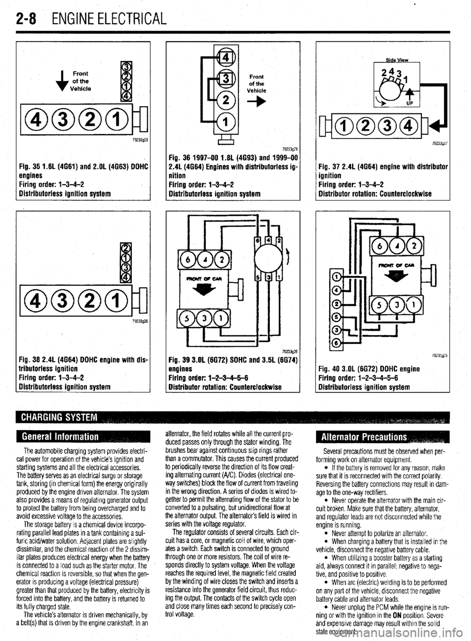
2-8 ENGINEELECTRICAL
Front
of the
Vehicle
Fig. 35 1.61(4661) and 2.OL (4663) DDHC
engines
Firing order: l-3-4-2
Distributorless ignition system
Fig. 36 2.4L (4664) DDHC engine with dis-
lributorless ignition
Firing order: l-3-4-2
gistributorless ignition system
Front
of the
Vehicle
+
Fig. 36 1997-00 1.6L (4693) and 1999-00
2.41(4664) Engines with distributorless ig-
nition
Firing order: l-3-4-2
Distributorless ignition system
792!33g26 Fig. 39 3.OL (6672) SDHC and 3.5L (6674)
engines
Firing order: l-2-3-65-6
Distributor rotation: Counterclockwise Fig. 37 2.4L (4664) engine with distributor
ignition
Firing order: l-3-4-2
Distributor rotation: Counterclockwise
:ig. 40 3.OL (6672) DDHC engine
Yring order: l-2-3-4-5-6
Iistributorless ignition system
The automobile charging system provides electri-
cal power for operation of the vehicle’s ignition and
starting systems and all the electrical accessories.
The battery serves as an electrical surge or storage
tank, storing (in chemical form) the energy originally
produced by the engine driven alternator. The system
also provides a means of regulating generator output
to protect the battery from being overcharged and to
avoid excessive voltage to the accessories.
The storage battery IS a chemical device incorpo-
rating parallel lead plates in a tank containing a sul-
furic acid/water solution. Adjacent plates are slightly
dissimilar, and the chemical reaction of the 2 dissim-
ilar plates produces electrical energy when the battery
is connected to a load such as the starter motor. The
chemical reaction is reversible, so that when the gen-
erator IS producing a voltage (electrical pressure)
greater than that produced by the battery, electricity is
forced into the battery, and the battery is returned to
its fully charged state.
The vehicle’s alternator is driven mechanically, by
a belt(s) that is driven by the engine crankshaft. In an alternator, the field rotates while all the current pro-
duced passes only through the stator winding. The
brushes bear against continuous slip rings rather
than a commutator. This causes the current produced
to periodically reverse the direction of its flow creat-
ing alternating current (A/C). Diodes (electrical one-
way switches) block the flow of current from traveling
in the wrong direction. A series of diodes is wired to-
gether to permit the alternating flow of the stator to be
converted to a pulsating, but unidirectional flow at
the alternator output, The alternators field is wired in
series with the voltage regulator.
The regulator consists of several circuits. Each cir-
cuit has a core, or magnetic coil of wire, which oper-
ates a switch. Each switch is connected to ground
through one or more resistors. The coil of wire re-
sponds directly to system voltage. When the voltage
reaches the required level, the magnetic field created
by the winding of wire closes the switch and inserts a
resistance into the generator field circuit, thus reduc-
ing the output. The contacts of the switch cycle open
and close many times each second to precisely con-
trol voltage. Several precautions must be observed when per-
forming work on alternator equipment.
l If the battery is removed for any reason, make
sure that it is reconnected with the correct polarity.
Reversing the battery connections may result In dam-
age to the one-way rectifiers.
l Never operate the alternator with the main cir-
cuit broken. Make sure that the battery, alternator,
and regulator leads are not disconnected while the
engine is running.
l Never attempt to polarize an alternator. l When charging a battery that is installed in the
vehicle, disconnect the negative battery cable.
l When utilizing a booster battery as a starting
aid, always connect it in parallel; negatrve to nega-
tive, and positive to positrve.
l When arc (electric) welding is to be performed
on any part of the vehicle, disconnect the negative
battery cable and alternator leads.
l Never unplug the PCM while the engine is run-
ning or with the ignition in the ON position. Severe
and expensive damage may result within the solid
state equipment.
Page 56 of 408
ENGlNEELECTRldAL 2-9
TESTING
Voltage Test able for use by customers. An alternator
bench test is the most definitive way to de-
termine the condition of your alternator.
REMOVAL&INSTALLATION
1. Make sure the engine is OFF, and turn the 1.51,1.61, 1.6L, 2.OL and 2.4L Engines
headlights on for 15-20 seconds to remove any sur-
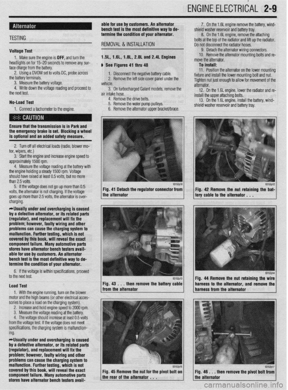
face charge from the battery. , See Figures 4, thru 48
2. Using a DVOM set to volts DC, probe across
1. Disconnect the negative battery cable.
the battery terminals.
3. Measure the battery voltage. 2. Remove the left side cover panel under the
vehicle.
4. Write down the voltage reading and proceed to
3. On turbocharaed Galant models, remove the
the next test.
air intake hose. -
No-load Test
1. Connect a tachometer to the engine. 4. Remove the drive belts.
5. Remove the water pump pulleys.
6. Remove the alternator upper bracket/brace.
Ensure that the transmission
is in Park and the emergency brake is set. Blocking a wheel
is optional and an added safety measure.
2. Turn off all electrical loads (radio, blower mo-
tor, wipers, etc.)
3. Start the engine and increase engine speed to
approximately 1500 rpm.
4. Measure the voltage reading at the battery with
the engine holding a steady 1500 rpm. Voltage
should have raised at least 0.5 volts, but no more
than 2.5 volts.
5. If the voltage does not go up more than 0.5
volts, the alternator is not charging. If the voltage
goes up more than 2.5 volts, the alternator is over-
* 7. On the 1.6L engine remove the battery, wind-
shield washer reservoir and battery tray.
8. On the 1.6L engine, remove the attaching
bolts at the top of the radiator and lift up the radiator.
Do not disconnect the radiator hoses.
9. Detach the alternator wiring connectors.
10. Remove the alternator mounting bolts and re-
move the alternator.
To install:
11. Position the alternator on the lower mountina
fixture and install the lower mounting bolt and nut. U
Tighten nut just enough to allow for movement of the
alternator.
12. On the 1.6L engine, lower the radiator and re-
install the upper attaching bolts.
13. On the 1.6L engine, install the battery, wind-
shield washer reservoir and battery tray.
/ tery cable to the alternator . , . 93152p12 Fig 42 Remove the nut retaining the bat-
cnargmg.
*Usually under and overcharging is‘caused
by a defective alternator, or its related parts
(regulator), and replacement will fix the
problem; however, faulty wiring and other
problems can
cause the charging system to
malfunction. Further testing, which is not
covered by this book, will reveal the exact
component failure. Many automotive parts
stores have alternator bench testers avaii-
able for use by customers. An alternator
bench test is the most definitive way to de-
termine the condition of your alternator.
6. If the voltage is within specifications, proceeU
to the next test.
Load Test
1. With the engine running, turn on the blower
motor and the hioh beams (or other electrical acces-
sories to place aioad on the charging system). Fig. 44 Remove the nut retaining the
then remove the batte harness to the alternator and remov
,
2. Increase and hold engine speed to 2000 rpm.
3. Measure the voltage reading at the battery.
4. The voltage should increase at least 0.5 volts
from the voltage test. If the voltage does not meet
specifications, the charging system is malfunction-
ing.
*Usually under and overcharging is caused
by a defective alternator, or its related parts
(regulator), and replacement will fix the
problem; however, faulty wiring and other
problems can cause the charging system to
malfunction. Further testing, which is not
covered by this book, will reveal the exact
component failure. Many automotive parts
stores have alternator bench testers avaii-
93152p17 en remove the pivot bolt from
Page 57 of 408
.
2-10 ENGINEELECTRICAL 1
2. Disconnect and remove the air intake hose.
3. Loosen the tensioner pulley and remove the
alternator drive belt.
4. On California models, remove the rear bank
converter assembly.
5. Remove the engine roll stopper stay bracket
assembly.
6. On the 3.OL SDHC engine, disconneCt the
EGR temperature sensor wire and remove the EGR
pipe assembly.
7. On the 3.OL SOHC engine, remove the intake
plenum stay bracket assembly.
8. Detach the alternator wiring harness connec-
tors.
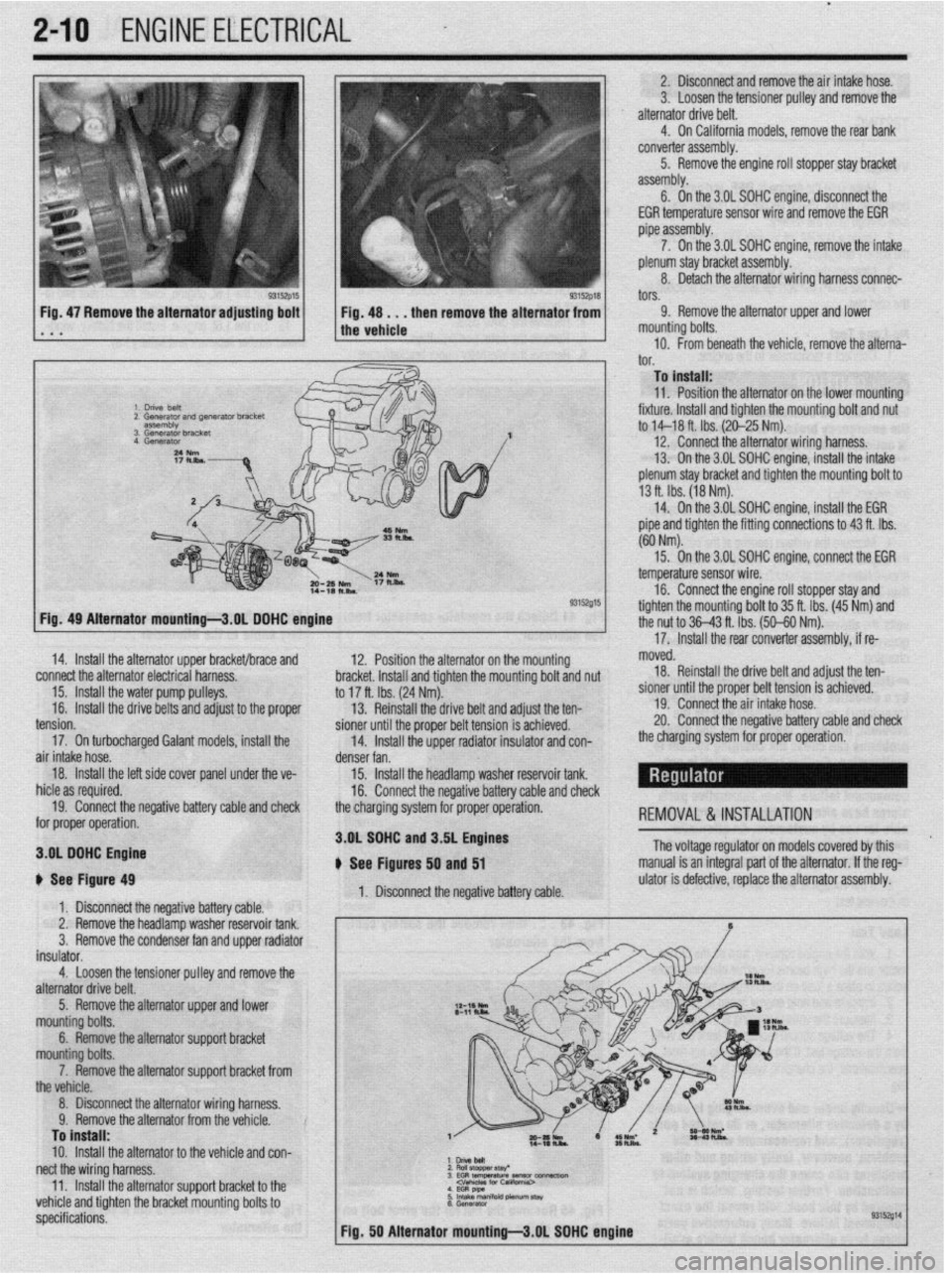
Fig, 47 Remove the alternator adjusting bolt
. a a 9. Remove the alternator upper and lower
mounting bolts.
10. From beneath the vehicle, remove the alterna-‘
I^”
._. To install:
11. Position the alternator on the lower mountino
fixture. Install and tighten the mounting bolt and nu<
to M-18 ft. Ibs. (20-25 Nm).
12. Connect the alternator wiring harness.
13. On the 3.OL SOHC engine, install the intake
plenum stay bracket and tighten the mounting bolt to
13 ft. Ibs. (18 Nm).
14. On the 3.OL SOHC engine, install the EGR
pipe and tighten the fitting connections to 43 ft. Ibs.
(60 Nm).
93152015
12. Position the alternator on the mour
sting hmrkd lnrtnll rmr( tinhtnn thn mm dim L VIUVI,VL. lllcllUll Ully llylllvll LltU ,,tvuln,,ly volt and nut
to 17 ft. Ibs. (24 Nm).
13. Reinstall the drive belt and adjust the ten-
pinnor fmtil the nmnor hdt toncinn ic art-:--~
15. On the 3.OL SOHC enoine. connect the EGR
- temperature sensor wire.
16. Connect the engine roll stopper stay and
tighten the mountina bolt to 35 ft. Ibs. (45 Nm) and
the nut to 36-43 ft. Tbs. (50-60 Nm).
’
17. Install the rear converter assembly, if re- Fia. 49 Alternator mountinu-3.0L DOHC enoine
14. Install the alternator upper bracket/brace and
connect the alternator electrical harness.
15. Install the water pump pulleys.
16.
Install the drive belts and adjust to the proper moved.
18. Reinstall the drive belt and adjust the ten-
sioner until the proper belt tension is achieved.
19. Connect the air intake hose.
20. Connect the neoativa hatterv rzahle and check -_. -_. __. _. _=-__
_ _-.._. , ___ _ _. _ _ _ _
the charoina system for orooer ooeration. - - _ -rr- -- - I Ull” Yvll air intake hose.
denser fan.
18.
Install the left side cover panel unde
r the ve-
15. Install the headlamp washer reservoir tank.
hid@ zx ran~kwl 1IIVI” YY ‘“~“““Y.
16. Connect the negative battery cable and check
19. Connect the negative battery cable and check
the charging svstem for proper operation.
-,-.- for proper operation. REMOVAL &INSTALLATION
3.OL SOHC n C, n---I_--
3.OL DOHC Engine
i fhs Itin** tension.
17. On turbocharged Galant models, install the
b See Figure 49
1. Disconnect the negative battery cable.
2. Remove the headlamp washer reservoir tank.
3.
Remove the condenser fan and upper radiator
insulator.
4.
Loosen the tensioner pulley and remove the
alternator drive belt. and J.DL engines
, - , lyures 50 and 51
1. Disconnect the negative battery cable. The voltage regulator on models covered by this
manual is an integral part of the alternator. If the reg-
ulator is defective, replace the alternator assembly.
5. Remove the alternator upper and lower
mounting bolts.
6. Remove the alternator support bracket
mn~lntinn h&c
_ _ _ _ -. ._ ,_._
--TT-.. -.--..-. ..-...
the vehicle.
8. Disconnect the alternator wiring harness.
Q Romnm thn slternatnr frnm thn mhirln V. llYlll”“Y LI1”“I~Y1IIU,“I II”,,, Lll” ,“,,,“,“. To install:
10.
Install the alternator to the vehicle and con-
nect the wiring harness. :z
E$llaf 3EG RtEWtiW~-~ 11
Install the alternatnr wnnnrt hrxket tn thp .._. -.. .._ - .._..._._.
--rT-.. -.--..-. .- I.._ .P _ vehicle and tighten the bracket mounting bolts to
specifications.
Page 58 of 408
ENGINE ELECTRICAL 2-11
l.unVeMlil(GSflWtWJ
2.Gwwator harness con- connectk,,,
3. Engme OS, level d,pst,&
4 Generator
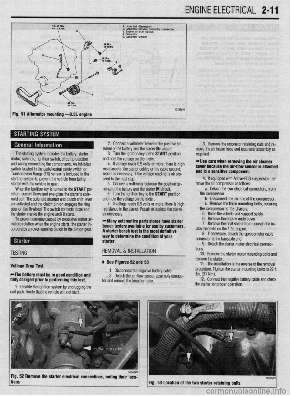
Fig. 51 Alternator mounting -3.51 engine
The starting system includes the battery, starter
motor, solenoid, ignition switch, circuit protection
and wiring connecting the components. An inhibitor
switch located in the park/neutral safety switch or
Transmission Range (TR) sensor is included in the
starting system to prevent the vehicle from being
started with the vehicle in gear.
When the ignition key is turned to the START po-
sition, current flows and energizes the starters sole-
noid coil. The solenoid plunger and clutch shift lever
are activated and the clutch pinion engages the ring
gear on the flywheel. The switch contacts close and
the starter cranks the engine until it starts.
To prevent damage caused by excessive starter ar-
mature rotation when the engine starts, the starter in-
corporates an over-running clutch in the pinion gear. 2. Connect a voltmeter between the positive ter-
minal of the battery and the starter B+ circuit.
3. Turn the ignition key to the START position
and note the voltage on the meter.
4. If voltage reads 0.5 volts or more, there is high
resistance in the starter cables or the cable ground,
repair as necessary. If the voltage reading is ok pro-
teed to the next step.
5. Connect a voltmeter between the positive ter-
minal of the battery and the starter M circuit,
6. Turn the ignition key to the START position
and note the voltage on the meter.
7. If voltage reads 0.5 volts or more, there is high
resistance in the starter. Repair or replace the starter
as necessary.
*Many automotive parts stores have starter
bench testers available for use by customers.
A starter bench test is the most definitive
way to determine the condition of your
starter. 3. Remove the resonator retaining nuts and re-
move the air intake hose and resonator assembly as
required.
rllse care when removing the air cleaner
cover because the air-flow sensor is attached
and is a sensitive component.
4. If equipped with Active-ECS suspension, re-
move the air compressor as follows:
a. Detach the two electrical connectors, from
the compressor.
b. Disconnect the air line at the compressor.
c. Remove the three mounting bolts, securing
the compressor to the chassis.
5. Raise the vehicle and support safely.
6. Remove the engine undercover.
7. Remove the heat shield from beneath the in-
take manifold on the 1.5L engine.
8. If necessary, detach the speedometer cable
connector at the transaxle end.
9. Detach the starter motor electrical connac-
TESTING
Voltage Drop Test
*The battery must be in good condition and
fully charged prior to performing this test. REMOVAL&INSTALLATION
# See Figures 52 and 53
1. Disconnect the negative battery cable.
2. Detach the air-flow sensor assembly connec-
tor and remove the breather hose.
1. Disable the ignition system by unplugging the
coil pack. Verify that the vehicle will not start. tions.
10. Remove the starter motor mounting bolts and
remove the starter.
11. The installation is the reverse of the removal
procedure. Tighten the starter mounting bolts to 22 ft.
Ibs. (31 Nm).
12. Connect the negative battery cable and check
the starter for proper operation.
9315zp19 Fig. 53 Location of the two starter retaining bolts