1900 MITSUBISHI DIAMANTE fuse
[x] Cancel search: fusePage 10 of 408
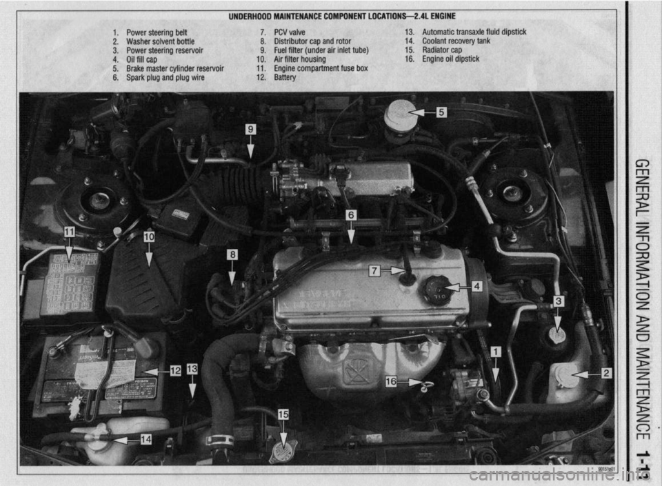
UNDERHDDD MAINTENANCE COMPONENT LOCATIONS-2AL ENGINE
II
1. Power steering belt 7. PCV valve
2. Washer solvent bottle 8. Distributor cap and rotor
3. Power steering reservoir 9. Fuel filter (under air inlet tube)
4. Oil fill cap 10. Air filter housing
5. Brake master cylinder reservoir 11. Engine compartment fuse box
6. Spark plug and plug wire 12. Battery 13. Automatic transaxle fluid dipstick
14. Coolant recovery tank
15. Radiator cap
16. Engine oil dipstick
Page 11 of 408
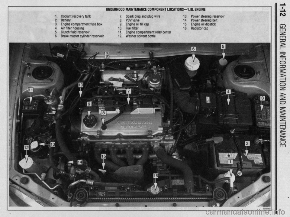
UNDERHOOD MAINTENANCE COMPONENT LOCATIONS-l .8L ENGINE
1. Coolant recovery tank
2. Battery
3. Engine compartment fuse box
4. Air filter housing
5. Clutch fluid reservoir
6. Brake master cylinder reservoir 7. Spark plug and plug wire
8. PCV valve
9. Engine oil fill cap
10. Fuel filter
11. Engine compartment relay center
12. Washer solvent bottle 13. Power steering reservoir
14. Power steering belt
15. Engine oil dipstick
16. Radiator cap
Page 28 of 408
GENERALINFORMATIONAND MAlNTENANdE 1-29
i
*Bug screens which are mounted in front of
the condenser (unless they are original
equipment) are regarded as obstructtons.
l The condensation drain tube expels any water
which accumulates on the bottom of the evaporator
housing into the engine compartment. If this tube is
obstructed, the air conditioning performance can be
restricted and condensation buildup can spill over
onto the vehicle’s floor.
l Make sure the air passage selection lever is
operating correctly. Start the engine and warm it to
normal operating temperature, then make sure the
temperature selection lever is operating correctly.
-w
~1 ELEMENT(REFILL)CARE& REPLACEMENT
SYSTEM INSPECTION
b See Figure 125 b See Figures 126 thru 135
For maximum effectiveness and longest element
Although the A/C system should not be serviced
by the do-it-yourselfer, preventive maintenance can
be practiced and A/C system inspections can be per-
formed to help maintain the efficiency of the vehicle’s
A/C system. For A/C system inspection, perform the
following:
The easiest and often most important check for the
air conditioning system consists of a visual inspec-
tion of the system components. Visually inspect the
air conditioning system for refrigerant leaks, dam-
aged compressor clutch, abnormal compressor drive
belt tension and/or condition, plugged evaporator
drain tube, blocked condenser fins, disconnected or
broken wires, blown fuses, corroded connections and
poor insulation.
A refrigerant leak will usually appear as an oily
residue at the leakage point in the system. The oily
residue soon picks up dust or dirt particles from the
surrounding air and appears greasy. Through time,
this will build up and appear to be a heavy dirt im-
pregnated grease.
For a thorough visual and operational inspection,
check the following: * Check the surface of the radiator and con-
denser for dirt, leaves or other material which might
block air flow.
l Check for kinks in hoses and lines. Check the
system for leaks.
l Make sure the drive belt is properly tensioned.
When the air conditioning is operating, make sure the
drive belt is free of noise or slippage.
l Make sure the blower motor operates at all ap-
propriate positions, then check for distribution of the
air from all outlets with the blower on HIGH or MAX.
*Keep in mind that under conditions of high
humidity, air discharged from the A/C vents
may not feel as cold as expected, even if the
system is working properly. This is because
vaporized moisture in humid air retains heat
more effectively than dry air, thereby making
humid air more difficult to cool.
lifp thp winrkhi&i nnri winor hlarlP~ shmM hP kmt . ..“. .I.” . . * ““I.. “.” I..” ...r”* “.“““” “, ,““,” “” ,~“r~ clean. Dirt, tree sap, road tar and so on will cause
streaking, smearing and blade deterioration if left on
the glass. It is advisable to wash the windshield care-
fully with a commercial glass cleaner at least once a
month. Wipe off the rubber blades with the wet rag
afterwards. Do not attempt to move wipers across the
windshield by hand; damage to the motor and drive
mechanism will result.
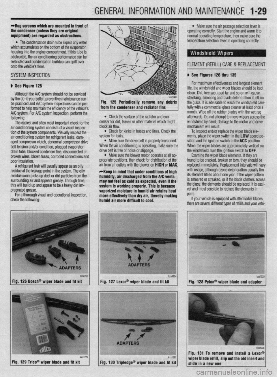
To inspect and/or replace the wiper blade ele-
ments, place the wiper switch in the LOW speed po-
sition and the ignition switch in the ACC position.
When the wiper blades are approximately vertical on
the windshield, turn the ignition switch to OFF.
Examine the wiper blade elements. If they are
found to be cracked, broken or torn, they should be
replaced immediately. Replacement intervals will vary
with usage, although ozone deterioration usually lim-
its element life to about one year. If the wiper pattern
is smeared or streaked, or if the blade chatters across
the glass, the elements should be replaced. It is easi-
est and most sensible to replace the elements in
pairs.
If your vehicle is equipped with aftermarket blades,
there are several different types of refills and your vehi-
tcca-23 Fig. 126 Bosch@ wiper blade and fft kit
Fig. 129 T&o* wioer blade and fit kit tCS1224
lW1Z?5 Fig. 127 LexoP wiper blade and fit kit
Fig. 128 Pylon@ wiper blade and adapter
Fig. 131 To remove and install a LexoP
Fig, 130 Tripledge@ wiper blade and fit kit wiper blade refill, slip out the old insert and
slide in a new one
Page 59 of 408
.
2-12 ENGINEELECTRICAL
*This section describes the operating prina
ciples of sending units, warning lights and
gauges. Sensors which provide information
to the Enafne Control Unit (ECU) or Electronic
or Power&in Control Module (FCM/PCM) are
covered in Section 4 of this manual.
Instrument panels contain a number of indicating
devices (gauges and warning lights). These devices
are composed of two separate components. One is
the sending unit, mounted on the engine or other re-
mote part of the vehicle, and the other is the actual
gauge or light in the instrument panel.
Several types of sending units exist, however most
can be characterized as being either a pressure type
or a resistance type. Pressure type sending units
convert liquid pressure into an electrical signal which
is sent to the gauge. Resistance type sending units
are most often used to measure temperature and use
variable resistance to control the current flow back to
the indicatinq device. Both types of sendinq units are
connected inseries by a wimto the batteryithiough
the ignition switch). When the ignition is turned ON,
current flows from the battery through the indicating
device and on to the sending unit.
89572$43 Fig. 54 Place the sending unit in water and
measure the resistance
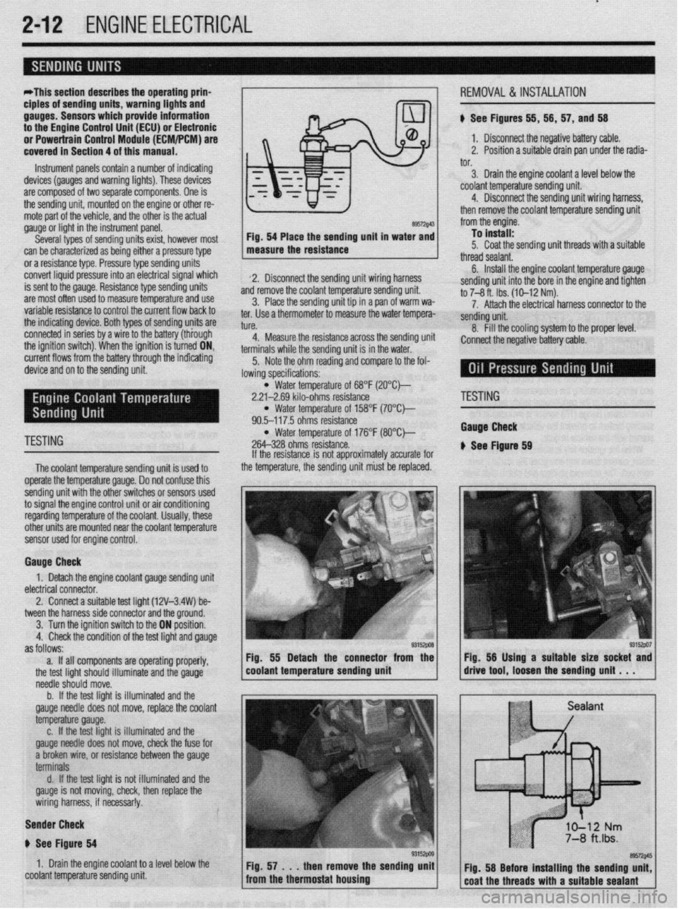
2. Disconnect the sending unit wiring harness
and remove the coolant temperature sending unit.
3. Place the sending unit tip in a pan of warm wa-
ter. Use a thermometer to measure the water tempera-
tl KP
L”,“.
4. Measure the resistance across the sending uni
terminals while the sending unit is in the water.
5. Note the ohm reading and compare to the fol-
lowing specifications: i, 56, 57, and 56
1. Disconnect the negative battery cable.
2. Position a suitable drain pan under the radia-
tor.
3. Drain the engine coolant a level below the
coolant temperature sending unit.
4. Disconnect the sending unit wiring harness,
then remove the coolant temperature sending unit
from the engine.
To install:
5. Coat the sending unit threads with a suitable
thread sealant.
6. Install the engine coolant temperature gauge
sending unit into the bore in the engine and tighten
to 7-8 ft. Ibs. (10-12 Nm).
7. Attach the electrical harness connector to the
sendina unit.
8. fill the cooling system to the proper level.
:onnect the negative battery cable.
l Water temperature of 68°F (2O”C)-
2.21-2.69 kilo-ohms resistance
l Water temperature of 158°F (7O’Ck
90.5-117.5 ohms resistance
TESTING l Water temperature of 176°F (8O”C)-
264-328 ohms resistance.
The coolant temperature sendina unit is used to
operate the temperature gauge. Donot confuse this
sending unit with the other switches or sensors used
to signal the engine control unit or air conditioning
regarding temperature of the coolant. Usually, these
other units are mounted near the coolant temoerature
sensor used for engine control. If the resistance is not approximately accurate for
the temperature, the sending unit must be replaced.
Gauge Check
1. Detach the engine coolant gauge sending unit
electrical connector.
2. Connect a suitable test liaht (12V-3.4W) be-
tween the harness side connector and the around.
I
3. Turn the ignition switch to the ON position.
4. Check the condition of the test light and gauge
as follows:
a. If all components are operating properly,
the test light should illuminate and the gauge
needle should move.
b. If the test light is illuminated and the
gauge needle does not move, replace the coolant
temperature gauge.
c. If the test light is illuminated and the
gauge needle does not move, check the fuse for
a broken wire, or resistance between the gauge
terminals
d. If the test light is not illuminated and the
gauge is not moving, check, then replace the
wiring harness, if necessar!y.
Sender Check
p See Figure 64
1. Drain the engine coolant to a level below the
coolant temperature sending unit Fig. 55 Detach the connector from the
coolant temperature sending unit
'ESTING
tauga Check
See Ftgure 69
Page 112 of 408
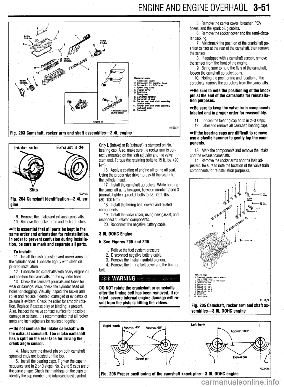
ENGlNEANDENGlNEOVERHALiL 3-51
:ig. 203 Camshaft, rocker arm and shaft assemblies-2.41 engine 9315393'
Intake side Exhaust side
7923PG57 Fig. 204 Camshaft identification-2.41 en-
gine
9. Remove the intake and exhaust camshafts.
10. Remove the rocker arms and lash adjusters
*It is essential that all parts be kept in the
same order and orientation for reinstallation.
In order to prevent confusion during installa-
tion, be sure to mark and separate all parts.
To install:
11. Install the lash adjusters and rocker arms into
the cylinder head. Lubricate lightly with clean oil
prior to installation.
12. Lubricate the camshafts with heavy engine oil
and position the camshafts on the cylinder head.
13 Check the camshaft journals and lobes for
wear or damage. Also, check the cylinder head oil
holes for clogging. Visually inspect the rocker arm
roller and replace if dented, damaged or evidence of
seizure is evident. Check the roller for smooth rota-
tion. Replace If excess play or binding is present.
Also, inspect the valve contact surface for possible
damage or seizure. It is recommended that all rocker
arms and lash adjusters be replaced together.
*Do not confuse the intake camshaft with
the exhaust camshaft. The intake camshaft
has a split on the rear face for driving the ,
crank angle sensor.
14. Make sure the dowel pin on both camshaft
sprocket ends are located on the top.
15. Install the bearing caps. Tighten the caps in
sequence and rn 2 or 3 steps. No 2 and 5 caps are of
the same shape. Check the markings on the caps to
identify the cap number and intake/exhaust symbol. Only 1 (intake) or I? (exhaust) is stamped on No. 1
bearing cap Also, make sure the rocker arm is cor-
rectly mounted on the lash adjuster and the valve
stem end. Torque the retaining bolts to 15 ft. Ibs. (20
Nm).
16. Apply a coating of engine oil to the oil seal.
Using the proper size driver, press-fit the seal into
the cylinder head.
17. Install the camshaft sprockets. While holding
the camshaft at its hexagon, between number 2 and 3
journals tighten sprocket bolts to 58-72 ft. Ibs.
(80-l 00 Nm).
18. Install the timing belt, covers and related
components.
19. Install the valve cover, using new gasket, and
reconnect all related components
20. Reconnect the negative battery cable.
3.OL DOHC Engine
# See Figures 205 and 206
1. Relieve the fuel system pressure.
2. Disconnect negative battery cable.
3. Remove the intake manifold plenum.
4. Remove the timing belt cover and the timing
belt.
DO NOT rotate the crankshaft or camshafts
after the timing belt has been removed. If ro-
tated, severe internal engine damage will re-
sult from the pistons hitting the valves.
5. Remove the center cover, breather, PCV
hoses, and the spark plug cables.
6. Remove the rocker cover and the semi-circu-
lar packing.
7. Matchmark the position of the crankshaft po-
sition sensor at the rear of the camshaft, then remove
the sensor.
8. If equipped with a camshaft sensor, remove
the sensor from the front of the engine.
9 Being sure to hold the flats of the camshaft,
loosen the camshaft sprocket bolts.
10. Noting the positionmg and location of the
sprockets, remove the sprockets from the camshafts.
*Be sure to note the positioning of the knock
pin at the end of the camshafts for reinstalla-
tion purposes.
*Be sure to keep the valve train components
labeled and in proper order for reassembly.
11. Loosen the bearing cap bolts in 2-3 steps.
12. Label and remove all camshaft bearing caps.
*If the bearing caps are difficult to remove,
use a plastic hammer to gently tap the com-
ponents.
13. Mark the components and remove the intake
and the exhaust camshafts.
14. Remove the rocker arms and the lash ad-
justers. Be sure to note the location of the valve train
components for reinstallation purposes.
1 semblies-3.01 DOHC engine
I
Left bank
7923PG58 Fig. 206 Proper positioning of the camshaft knock pins-3.01 DOHC engine
Page 113 of 408
.
3-52 ENGINEANDENGINEOVERHAUL
15. Check the camshaft journals for wear or dam-
age. Check the cam lobes for damage. Also, check
the cylinder head oil holes for clogging.
To install:
*Lubricate the valve train components with
clean engine oil.
16. Bleed and install the lash adjusters to the to
the original bores in the cylinder head.
17. Install the rocker arms to the cylinder head.
18. Lubricate the camshafts with clean engine oil
and position the camshafts on the cylinder head
Be sure to properly position the knock pins of
the camshaft to prevent valve to piston inter-
ference.
*Do not confuse the intake camshaft with
the exhaust camshaft. The intake camshaft
on the Diamante has a B or J stamped on the
hexagon depending on the application. The
exhaust camshaft on the Diamante has a D or
K stamped on the hexagon depending on ap-
plication.
-Install the bearing caps according to the
identification mark and cap number. Bearing
caps No. 2,3 and are marked as such. The
caps also are marked I for intake or E for ex-
haust.
19 Install the bearing caps. Tighten the caps in
sequence, gradually in 2 or 3 steps Caps 2,3 and 4
have a front mark. Install with the mark aligned with
the front mark on the cylinder head. Torque the re-
taining bolts for caps No. 2,3 and 4 to 8 ft. Ibs. (11
Nm) and torque the retaining bolts for the front and
rear caps to 14 ft. Ibs. (20 Nm).
20. Apply a coating of engine oil to the oil seals
and install the oil seals to the front and rear of the
camshafts.
21. Holding the flats of the camshaft, install and
tighten the sprocket bolts to 65 ft. Ibs. (90 Nm).
22. If removed, install the camshaft position sen-
sor and tighten the mounting bolts to 78 inch Ibs. (9
Nm).
23. Aligning the matchmark, install the crankshaft
position sensor at the rear of the camshaft and
tighten the mountrng nut to 7 ft. Ibs. (12 Nm).
24. Align the marks on the camshaft and crank-
shaft sprockets. Install the timing belt assembly.
25. Install the rocker cover and the semi-circular
packing.
26. Install the intake manifold plenum.
27. Install the spark plug cables, center cover,
breather and PCV hoses.
28. Connect the negative battery cable and check
for leaks.
3.OL SDHC Engine
ti See Figures 207, 208, 209, and 210
1. Disconnect the negative battery cable,
2. Rotate and position the engine to TDC of
compression stroke.
3. If removing the right side (front) camshaft,
matchmark the distributor rotor and distributor hous-
ing to the engine block and remove the distributor.
4. Remove the Intake manifold plenum stay
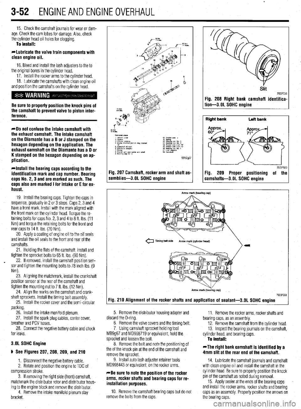
bracket. Fig. 207 Camshaft, rocker arm and shaft as-
iemblies-3.01 SDHC engine
Siit 7923'659 Fig. 208 Right bank camshafl identifica-
tion-3.01 SDHC engine
Right bank
Left bank
7923PG60 Fig. 209 Proper positioning of the
:amshafts-3.OL SDHC enoine
Tmng bolt side Armwmark(cql~ndertmad)
7923PG61
:ig. 210 Alignment of the rocker shafts and application of sealant-3.01 SDHC engine
5. Remove the distributor housing adapter and
,. ,.^.
bearmg caps, as an assembly 11. Remove the rocker arms, rocker shafts and
aiscara tne u-rmg.
^ -
6; Kemove the valve covers and the tlmmg belt.
7 Using camshaft sprocket holding tool
MB9g67 and MD998719 or equivalent, hold the
sprocket and loosen the bolt.
8. Remove the bolt and note the positioning of
the of the knock pin at the end of the camshaft and
remove the sprocket.
9. Install auto lash adjuster retainer tools
MD998443 or equivalent, on the rocker arms.
*Be sure to note the position of the rocker
arms, rocker shafts and bearing caps for re-
installation purposes.
10 Remove the camshaft bearing caps but do not
remove the bolts from the caps. 12. Remove the camshaft from the cylinder head.
13. Inspect the bearing journals on the camshaft,
cylinder head, and bearing caps.
To install:
*The right bank camshaft is identified by a
4mm slit at the rear end of the camshaft.
14. Lubricate the camshaft journals and camshaft
with clean engme oil and install the camshaft in the
cylinder head Be sure to properly position the knock
pin of the camshaft as noted during removal.
15. Apply sealer at the ends of the bearing caps
and install the rocker arms, rocker shafts and bearing
caps as an assembly Properly positron the arrows on
the bearing caps.
Page 169 of 408
4-26 DRIVEABILITYAND EMISSIONS CONTROLS
The Powertrain Control Module (PCM) monitors
the signals of input and output sensors, some all the
time and others at certain times and processes each
signal. When the PCM notices that an irregularity has
continued for a specified time or longer from when
the irregular signal was initially monitored, the PCM
judges that a malfunction has occurred and will
memorize the malfunction code. The code is then
stored in the memory of the PCM and is accessible
through the data link (diagnostic connector) with the
use of an electronic scan tool or a voltmeter.
CHECK ENGINE/MALFUNCTION
INDICATOR LIGHT
Among the on-board diagnostic items, a check
engine/malfunction indicator light comes on to notify
the driver of a emission control component irregular-
ity. If the irregularity detected returns to normal or the
PCM judges that the component has returned to nor-
mal, the check engine/malfunction indicator light will
be turned off Moreover, if the ignition is turned OFF
and then the engine is restarted, the check
engine/malfunction indicator light will not be turned
on unttl a malfunction is detected.
The check engine/malfunction indicator light will
come on immediately after the ignition switch is
turned ON. The light should stay lit for 5 seconds
and then will go off. This Indicates that the check en-
gine/malfunction indicator lamp is operating nor-
mally. This does not signify a problem with the sys-
tem.
*The check engine/malfunction indicator
lamp will come on when the terminal for the
ignition timing adjustment is shorted to
ground. Therefore, it is not abnormal that the
light comes on even when the terminal for ig-
nition timing is shorted at time of ignition
timing adjustment.
To test the light, perform the following:
1. Turn the ignition switch ON. Inspect the check
engine/malfunction indicator lamp for Illumination.
2. The light should be lit for 5 seconds and then
should go out.
3. If the lamp does not illuminate, check for open
circuit In the harness, blown fuse or blown bulb.
SERVICE PRECAUTIONS
l Before attachrng or detaching the PCM harness
connectors, make sure the ignition switch is OFF and
the negative battery cable is disconnected to avoid
the possibility of damage to the PCM.
l When performing PCM input/output signal di-
agnosis, remove the pin terminal retainer from the
connectors to make it easier to insert tester probes
into the connector.
l When attaching or detaching pin connectors ,
from the PCM, take care not to bend or break any pin
terminals. Check that there are no bends or breaks on
PCM pin terminals before attempting any connec-
tions.
l Before replacing any PCM, perform the PCM
input/output signal diagnosis to make sure the PCM
is functioning properly.
l When measuring supply voltage of PCM-con-
trolled components with a circuit tester, separate 1
tester probe from another. If the 2 tester probes acci-
dentally make contact with each other during mea-
surement, a short circuit WIII result and damage the
PCM.
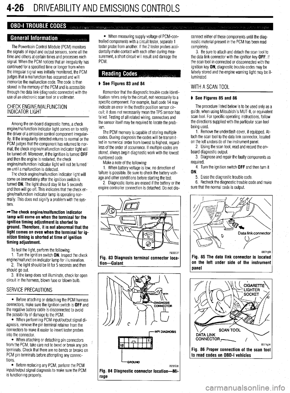
# See Figures 83
and 84
Remember that the diagnostic trouble code identi-
fication refers only to the circuit, not necessarily to a
specific component. For example, fault code 14 may
indicate an error in the throttle position sensor cir-
cuit; it does not necessarily mean the TPS sensor has
failed Testing of all related wiring, connectors and
the sensor itself may be required to locate the prob-
lem.
The PCM memory is capable of storing multiple
codes. During diagnosis the codes will be transmlt-
ted in numerical order from lowest to highest, regard-
less of the order of occurrence. If multiple codes are
stored, always begin diagnostic work with the lowest
numbered code
Make a note of the following:
1. When battery voltage IS low, no detection of
failure is possible. Be sure to check the battery volt-
age and other conditions before starting the test.
2. Diagnostic items are erased if the battery or the
engine controller connection is detached. Do not dis- connect either of these components until the diag-
nostic material present in the PCM has been read
completely.
3. Be sure to attach and detach the scan tool to
the data link connector with the ignition key OFF. If
the scan tool in connected or disconnected with the
ignition key ON, diagnostic trouble codes may be
falsely stored and the engine warning light may be il-
luminated. WITHASCANTOOL
) See Figures 85 and 86
The procedure listed below is to be used only as a
guide, when using Mitsubishi’s MUT-II, or equivalent
scan tool. For specific operating instructions, follow
the directions supplied with the particular scan tool
bemg used.
1. Remove the underdash cover, if equipped. At-
tach the scan tool to the data link connector, located
on the left underside of the instrument panel.
2. Using the scan tool, read and record the on-
board diagnostic output.
3. Diagnose and repair the faulty components as
required
4. Turn the ignition switch OFF and then turn it
ON.
5. Erase the diagnostic trouble code.
6 Recheck the diaanostic trouble code and make
sure that the normal &de is output.
79232G37 89574g98 Fig. 83 Diagnosis terminal connector loca-
tion-Galant Fig. 85 The data link connector is located
on the left under side of the instrumeni
panel
,--MU DL4GNDSl.S
LGRDIJND
79232638
Fig. 84 Diagnostic connector Iocation-Mi-
‘age
ata link connector
89574994 Fig. 86 Proper connection of the scan tool to read codes on OBD-I vehicles
Page 204 of 408
UNDERSTANDING AND
TROUBLESHOOTING
ELECTRICAL SYSTEMS 6-2
BASIC ELECTRICALTHEORY 6-2
HOW DOES ELECTRICITY WORK:
THEWATERANALOGY 6-2
OHM'S LAW 6-2
ELECTRICALCOMPONENTS 6-2
POWERSOURCE 6-2
GROUND 6-3
PROTECTIVE DEVICES 6-3
SWITCHES&RELAYS 6-3
LOAD 6-3
WIRING & HARNESSES 6-3
CONNECTORS 6-4
TEST EQUIPMENT 6-4
JUMPER WIRES 6-4
TEST LIGHTS 6-4
MULTIMETERS 6-5
TROUBLESHOOTING ELECTRICAL
SYSTEMS 6-5
TESTING 6-5
OPEN CIRCUITS 6-5
SHORT CIRCUITS 6-6
VOLTAGE 6-6
VOLTAGE DROP 6-6
RESISTANCE 6-8
WIRE AND CONNECTORREPAIR 6-6
BATTERY CABLES 6-7
DISCONNECTING THE CABLES 6-7
AIR BAG (SUPPLEMENTAL
RESTRAINT SYSTEM) 6-7
GENERALINFORMATION 6-7
SERVICE PRECAUTIONS 6-7
DISARMING 6-7
REARMING 6-7
HEATING AND AIR
CONDITIONING 6-7
BLOWER MOTOR 6-7
REMOVAL &INSTALLATION 6-7
HEATER CORE 6-9 INSTRUMENTS AND SWITCHES 6-17
INSTRUMENTCLUSTER 6-17
REMOVAL &INSTALLATION 6-17
GAUGES 6-18
REMOVAL&INSTALLATION 6-18
WINDSHIELD WIPER SWITCH 6-19
REMOVAL&INSTALLATION 6-19
REARWINDOWWIPERSWITCH 6-19
REMOVAL &INSTALLATION 6-19
DIMMER SWITCH 6-19
REMOVAL & INSTALLATION 6-19 .
HEADLIGHT SWITCH 6-19
REMOVAL & INSTALLATION 6-19
LIGHTING 6-19
HEADLIGHTS 6-19
REMOVAL &INSTALLATION 6-19
AIMINGTHEHEADLIGHTS 6-20
SIGNAL AND MARKER LIGHTS 6-21
REMOVAL &INSTALLATION 6-21
CIRCUIT PROTECTION 6-27
FUSES 6-27
REPLACEMENT 6-27
FUSIBLE LINKS 6-27
CIRCUIT BREAKERS 6-28
RESETTING AND/OR
REPLACEMENT 6-28
FLASHERS 6-28
REPLACEMENT 6-28
WIRING DIAGRAMS 6-31
REMOVAL & INSTALLATION 6-9
AIR CONDITIONING COMPONENTS 6-11
REMOVAL & INSTALLATION 6-11
CONTROLCABLES 6-12
ADJUSTMENT 6-12
CONTROL PANEL 6-12
REMOVAL & INSTALLATION 6-12
CRUISE CONTROL 6-13
ENTERTAINMENT SYSTEMS 6-14
RADIO RECEIVER/AMPLIFIER/TAPE
PLAYER/CD PLAYER 6-14
SPEAKERS 6-14
REMOVAL & INSTALLATION 6-14
WINDSHIELD WIPERS AND
WASHERS 6-15
WINDSHIELD WIPER BLADE AND
ARM 6-15
REMOVAL & INSTALLATION 6-15
WINDSHIELD WIPER MOTOR 6-16 _
REMOVAL &INSTALLATION 6-16
WINDSHIELD WASHER PUMP 6-17
REMOVAL &INSTALLATION 6-17