1900 MITSUBISHI DIAMANTE heater blower fan
[x] Cancel search: heater blower fanPage 45 of 408

.
I-46 GENERALINFORMATIONAND MAINTENANCE
2. Pull the jumping vehicle (with the good bat-
tery) into a position so the jumper cables can reach
the dead battery and that vehicle’s engine. Make sure
that the vehicles do NOT touch.
3. Place the transmissions/transaxles of both ve-
hicles in Neutral (MT) or P (AT), as applicable, then
firmly set their parking brakes.
*ff necessary for safety reasons, the hazard
lights on both vehicles may be operated
throughout the entire procedure without sig-
nificantiy increasing the diff icuity of jumping
the dead battery.
4. Turn all lights and accessories OFF on both
vehicles. Make sure the ignition switches on both ve-
hicles are turned to the OFF position.
5. Cover the battery cell caps with a rag, but do
not cover the terminals.
6. Make sure the terminals on both batteries are
clean and free of corrosion or proper electrical con-
nection will be impeded. If necessary, clean the bat-
tery terminals before proceeding.
7. Identify the positive (+) and negative (-) termi-
nals on both batteries.
8. Connect the first jumper cable to the positive
(t) terminal of the dead battery, then connect the
other end of that cable to the positive (t) terminal of
the booster (good) battery.
9. Connect one end of the other jumper cable to
the negative (−) terminal on the booster bat-
tery and the final cable clamp to an engine bolt head,
alternator bracket or other solid, metallic point on the
engine with the dead battery. Try to pick a ground on
the engine that is positioned away from the battery in
order to minimize the possibility of the 2 clamps
touching should one loosen during the procedure.
DO NOT connect this clamp to the negative (-) termi-
nal of the bad battery. cable on the donor battery. Disconnect the positive
cable from the donor battery and finally, disconnect
the positive cable from the formerly dead battery. Be
careful when disconnecting the cables from the posi-
tive terminals not to allow the alligator clips to touch
any metal on either vehicle or a short and sparks will
occur.
I
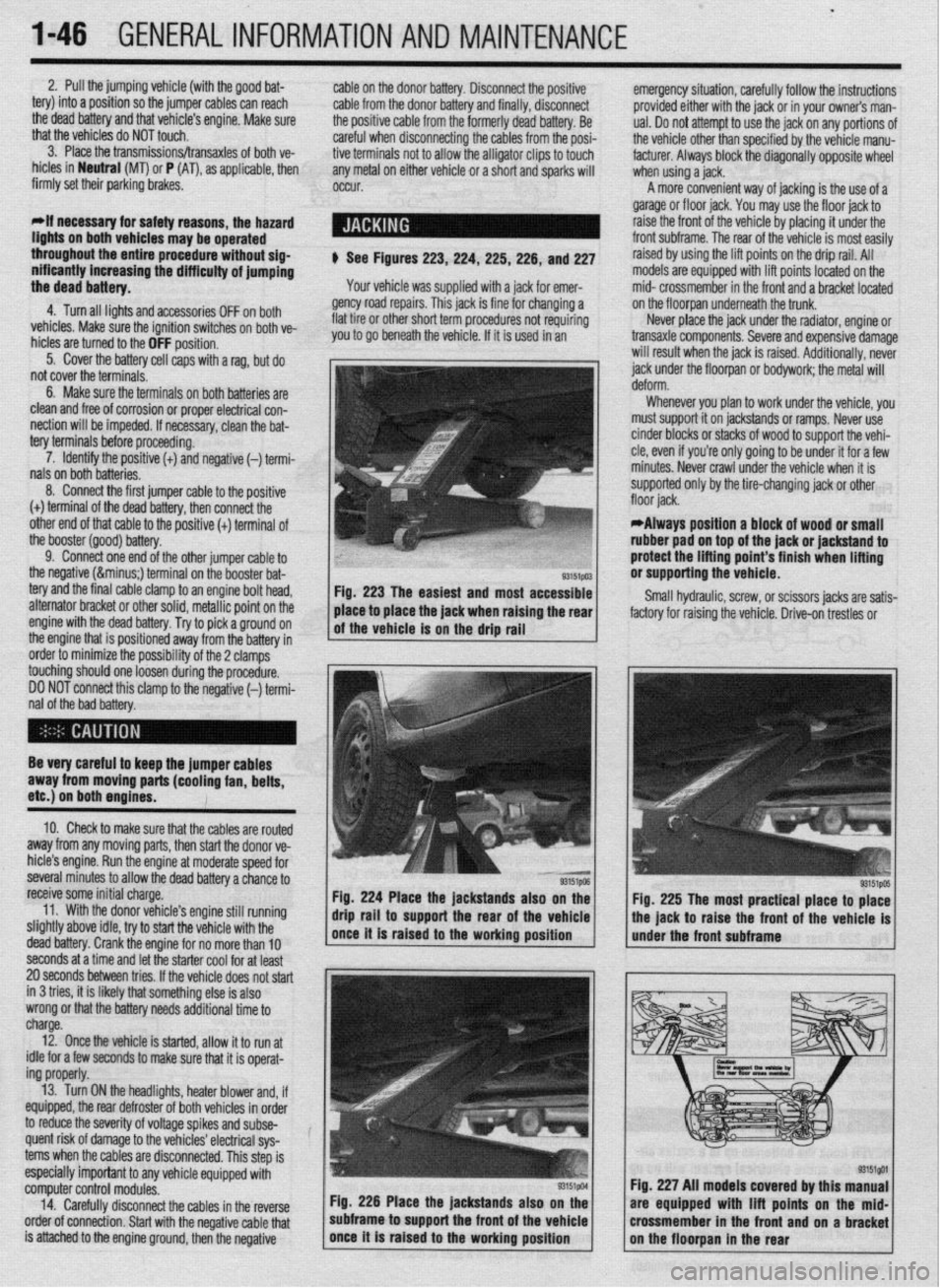
$ See Figures 223,224, 225,226, and 227
Your vehicle was supplied with a jack for emer-
gency road repairs. This jack is fine for changing a
flat tire or other short term procedures not requiring
you to go beneath the vehicle. If it is used in an emergency situation, carefully follow the instructions
provided either with the jack or in your owners man-
ual. Do not attempt to use the jack on any portions of
the vehicle other than specified by the vehicle manu-
facturer. Always block the diagonally opposite wheel
when using a jack.
A more convenient way of jacking is the use of a
garage or floor jack. You may use the floor jack to
raise the front of the vehicle by placing it under the
front subframe. The rear of the vehicle is most easily
raised by using the lift points on the drip rail. All
models are equipped with lift points located on the
mid- crossmember in the front and a bracket located
on the floorpan underneath the trunk.
Never place the jack under the radiator, engine or
transaxle components. Severe and expensive damage
will result when the jack is raised. Additionally, never
jack under the floorpan or
bodywork; the
metal will
Whenever you plan to work under the vehicle, you
must support it on jackstands or ramps. Never use
cinder blocks or stacks of wood to support the vehi-
cle, even if you’re only going to be under it for a few
minutes. Never crawl under the vehicle when it is
supported only by the tire-changing jack or other
*Always position a block of wood or small
rubber pad on top of the jack or jackstand to
protect the lifting point’s finish when lifting
or supporting the vehicle.
Small hydraulic, screw, or scissors jacks are satis-
factory for raising the vehicle. Drive-on trestles or
Be very careful to keep the jumper cables
away from moving parts (cooling fan, belts,
etc.) on both engines.
10. Check to make sure that the cables are routed
away from any moving parts, then start the donor ve-
hicle’s engine. Run the engine at moderate speed for
several minutes to allow the dead battery a chance to
receive some initial charge.
11. With the donor vehicle’s engine still running
slightly above idle, try to start the vehicle with the
dead battery. Crank the engine for no more than 10 &stands also on the
Fig. 225 The most practical place to place
front of the vehicle is
seconds at a time and let the starter cool for at least
20 seconds between tries. If the vehicle does not start
in 3 tries, it is likely thatsomething else is also
wrong or that the battery needs additional time to
charge.
12. Once the vehicle is started, allow it to run at
idle for a few seconds to make sure that it is operat-
ing properly.
13. Turn ON the headlights, heater blower and, if
equipped, the rear defroster of both vehicles in order
to reduce the severity of voltage spikes and subse-
quent risk of damage to the vehicles’ electrical sys-
tems when the cables are disconnected. This step is
especially important to any vehicle equipped with
computer control modules.
14. Carefully disconnect the cables in the’reverse
order of connection. Start with the negative cable that
is attached to the engine ground, then the negative Fig. 226 Place the jackstands also
subframe to support the front of the Fig. 227 All models covered by this
are equipped with lift points on t
crossmember in the front and on a
Page 211 of 408

6-8 CHASSIS ELECTRICAL
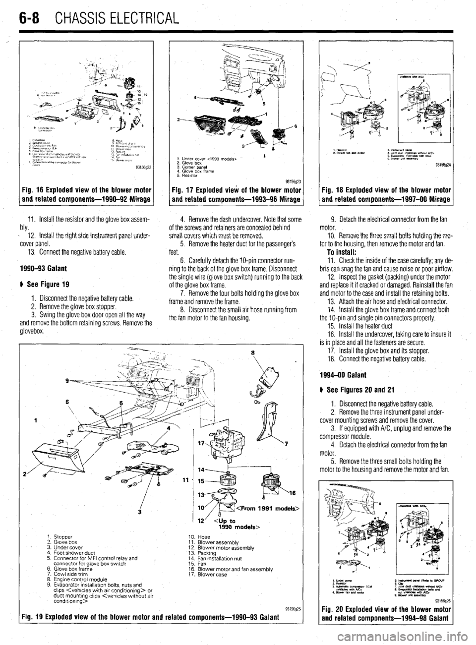
Fig. 16 Exploded view of the blower motor
and related components-1990-92 Mirage
11. Install the resistor and the glove box assem- W 12. Install the right side instrument panel under-
cover panel.
13. Connect the negative battery cable.
1990-93 Galant
# See Figure 19
1. Disconnect the negative battery cable.
2. Remove the glove box stopper.
3. Swing the glove box door open all the way
and remove the bottom retainina screws. Remove the
glovebox
1 Under cover 4993 models, 1
2 Glove box
3 corner pane,
4 Glove box frame
5 RBSlStOr
93156~23
Fig. 17 Exploded view of the blower motor
and related components-1993-96 Mirage
4. Remove the dash undercover. Note that some 9. Detach the electrical connector from the fan
ot the screws and retainers are concealed behind
small covers which must be removed.
5 Remove the heater duct for the passenger’s
feet.
6. Carefully detach the lo-pin connector run-
ning to the back of the glove box frame. Disconnect
the single wire (glove box switch) running to the back
of the glove box frame.
7. Remove the four bolts holding the glove box
frame and remove the frame.
8. Disconnect the small air hose running from
the fan motor to the fan housing. motor.
10. Remove the three small bolts holding the mo-
tor to the housing, then remove the motor and fan.
To install: 11. Check the inside of the case carefully: any de-
bris can snag the fan and cause noise or poor airflow.
12. Inspect the gasket (packing) under the motor
and replace it if cracked or damaged. Reinstall the fan
and motor to the case and Install the retaining bolts.
13. Attach the air hose and electrical connector.
14. Install the glove box frame and connect both
the lo-pin and sinqle pin connectors properly.
15. Install the heater duct
16. Install the undercover, taking care to insure it
is in place and all the fasteners are secure.
17. Install the glove box and its stopper.
18. Connect the negative battery cable.
:ig. 19 Exploded view of the blower motor and related components-1990-93 Galant
1. stopper
‘2 Glove box
3 Under cover
4 Foot shower duct
5 Connector for MFI control relay and ,
connector for glove box swtch
6 Glove box frame
7 Cowl side trim
8 Engine control module
9 Evaporator lnstallatlon bolts, nuts and
clips
duct mounting clips Kvehlcles wthout air
condltionlng>
Fig. 18 Exploded view of the blower motor
and related components-1997-00 Mirage
--.
8
12’
Blower assemblv
Blower motor assembly
Packtng
;;c, tnstallatlon nut
Blower motor and fan assembly
Blower case
1994-00 Galant
) See Figures 20 and 21
1. Disconnect the negative battery cable.
2. Remove the three instrument panel under-
cover mounting screws and remove the cover.
3 If equipped with A/C, unplug and remove the
compressor module.
4. Detach the electrical connector from the fan
motor.
5. Remove the three small bolts holding the
motor to the housing and remove the motor and fan.
; y&M 5 m- M ,RC m .3RcuP
3 lulomafs corn-r ECU :2%brtr-Mbi&C>
.“eM *nn mi
1 slmhn.m”m,n 8 ~y~tipJ*-m-=%9 md
S sa*n”nlUSW
931561
Fig. 20 Exploded view of the blower mote
and related comoonents-1994-98 Galan
Page 212 of 408

CHASSIS ELECtRldAL 6-9
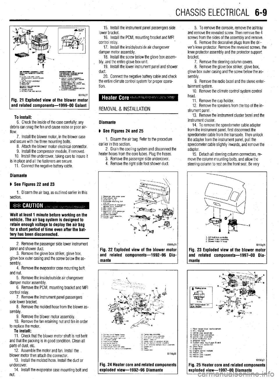
93156g27 Fig. 21 Exploded view of the blower motor
and related components-1999-00 Galant
To install:
6. Check the inside of the case carefully; any
debris can snag the fan and cause noise or poor air-
flow.
7. Install the blower motor, in the blower case
and secure with the three mounting bolts,
8. Attach the blower motor electrlcal connector,
9. Install the compressor module, if removed.
10. Install the undercover, takmg care to insure it
is in place and all the fasteners are secure.
11. Connect the negative battery cable.
Diamante
u See Figures 22 and 23
1. Disarm the air bag, as outlined earlier in this
section.
Wait at least 1 minute before working on the
vehicle. The air bag system is designed to
retain enough voltage to deploy the air bag
for a short period of time even after the bat-
tery has been disconnected.
2. Remove the passenger side lower instrument
panel and shower duct,
3. Remove the glove box striker, glove box,
glove box outer casing and the screw below the as-
sembly.
4. Remove the evaporator case mounting bolt
and nut.
5. Remove the inside/outside air changeover
damper motor assembly.
6 Remove the PCM, mounting bracket and MFI
control relay.
7. Remove the instrument panel passengers
side lower bracket.
8. Remove the molded hose from the blower as-
sembly.
9. Remove the blower motor assembly.
10. Remove the fan retaining nut and fan in order
to replace the motor,
To install: 11. Check that the blower motor shaft is not bent
and that the packing is in good condition, Clean all
parts of dust, etc.
12. Assemble the motor and fan. Install the
blower motor then attach the connector.
13. Install the molded hose. Install the duct or
undercover.
14. Install the evaporator case mounting bolt and
nut. 15. Install the instrument panel passengers side
lower bracket.
16. Install the PCM, mounting bracket and MFI
control relay.
17. Install the inside/outside air changeover
damper motor assembly.
18. Install the screw below the glove box assem-
bly, and the entire glove box unit.
19. Install the lower instrument panel and shower
duct.
20. Connect the negative battery cable and check
the entire climate control system for proper opera-
tion.
REMOVAL & INSTALLATION
Diamante
u See Figures 24
and 25
1. Disarm the air bag Refer to the procedure
earlier in this section.
2. Dram the cooling system and disconnect the
heater hoses from the core tubes. Plug the hoses.
3. Remove the passenger side undercover.
4. Remove the right side foot shower duct. 5. To remove the console, remove the ashtray
and remove the revealed screw. Then remove the 4
screws from the sides of the assembly and remove.
6. Remove the decorative plugs from the drl-
ver’s knee protector. Remove the revealed screws, the
knee protector assembly and the protector support
bracket.
7. Remove the steering column covers.
8. Remove the glove box striker, glove box,
glove box outer casing and the screw below the as-
sembly.
9. Remove the radio bezel and the stereo enter-
tainment system.
10. Remove the climate control system control
head.
11. Remove the cup holder.
12. Remove the speakers from the top of the in-
strument panel.
13. Remove the instrument cluster bezel and the
instrument cluster.
14. To remove the speedometer cable adapter
from the instrument panel, first disconnect the
speedometer cable from the transaxle. Then unlock
the adapter from the instrument panel, pull the
speedometer cable slightly inwards, and remove the
adapter
15. Detach all steering column connectors, re-
move the column mounting bolts, and allow the
steering column to rest on the front seat. Be very
Fig. 23 Exploded view of the blower motor
and related components-1997-00 Dia-
Fig. 25 Heater core and related components
exploded view-1997-00 Diamante
Page 398 of 408

II-16 TROUBLESHOOTING
c. Gauge sending unit defective. Replace gauge sending unit.
d. Gauge or sending unit improperly installed. Verify installation and wiring, and repair
1. Speedometer does not work
a. Check the speed sensor pickup and replace as necessary.
b. Check the wiring between the speed sensor and the speedometer for corroded termi-
nals, loose connections or broken wires and clean or repair as necessary.
c. Install a known good speedometer to test for proper operation. If the substituted
speedometer functions properly, replace the speedometer assembly.
2. Speedometer works intermittently
a. Check the wiring between the speed sensor and the speedometer for corroded termi-
nals, loose connections or broken wires and clean or repair as necessary.
b. Check the speed sensor pickup and replace as necessary. as necessary.
2. Gauge operates enatica//y
a. Checkfor ioose, shorted, damaged or corroded electrical connections or wiring and
repair as necessary.
b. Check gauge sending units and replace as necessary.
3. Gauge operates fully pegged
a. Sending unit-to-gauge wire shorted to ground.
b. Sending unit defective; replace sending unit.
c. Gauge or sending unit not properly grounded.
d. Gauge or sending unit improperly installed. Verify installation and wiring, and repair
as necessary.
I. Gauge does not register
a. Check for a missing or blown fuse and replace as necessary.
b. Check for an open circuit in the gauge wiring. Repair wiring as necessary.
I. No air coming from air conditioner vents
a. Check the air conditioner fuse and replace as necessary.
b. Air conditioner system discharged. Have the system evacuated, charged and leak
tested by an MVAC certified technician, utilizing approved recovery/recycling equip-
ment. Repair as necessary.
c. Air conditioner low pressure switch defective. Replace switch.
d. Air conditioner fan resistor pack defective. Replace resistor pack.
e. Loose connection, broken wiring or defective air conditioner relay in air conditioning*
electrical circuit. Repair wiring or replace relay as necessary.
2. Air conditioner blows warm air
a. Air conditioner system is discharged. Have the system evacuated, charged and leak
tested by an MVAC certified technician, utilizing approved recovery/recycling equip-
ment. Repair as necessary.
b. Air conditioner compressor clutch not engaging. Check compressor clutch wiring,
electrical connections and compressor clutch, and repair or replace as necessary.
3. Water collects on the interior floor when the air conditioner is used
a. Air conditioner evaporator drain hose is blocked. Clear the drain hose where it exits
the passenger compartment.
b. Air conditioner evaporator drain hose is disconnected. Secure the drain hose to the
evaporator drainage tray under the dashboard.
4. Air conditioner has a moldy odor when used
a. The air conditioner evaporator drain hose is blocked or partially restricted, allowing
condensation to build up around the evaporator and drainage tray. Clear the drain
hose where it exits the passenger compartment.
,
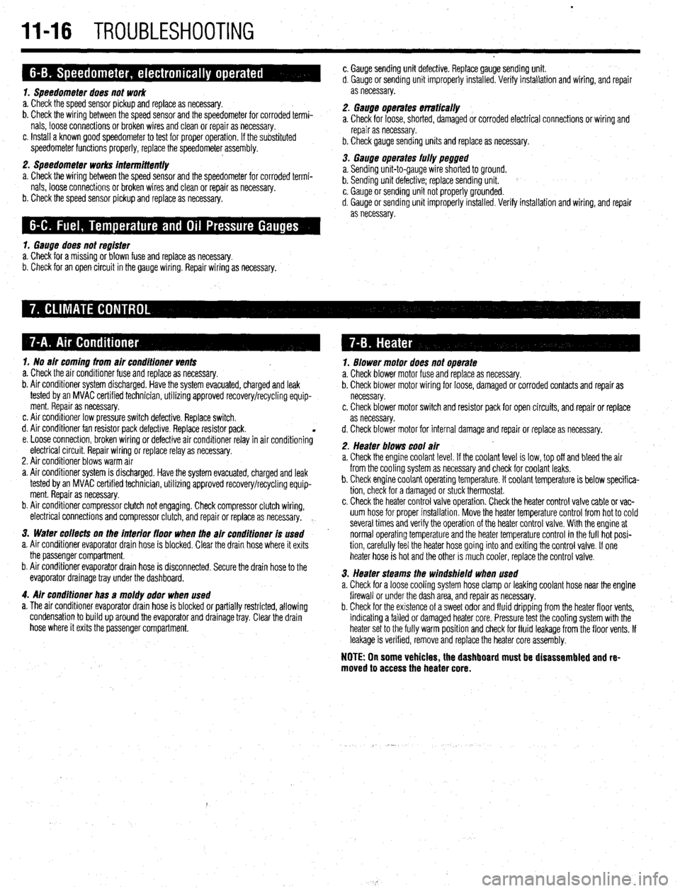
1. Blower motor does not operate
a. Check blower motor fuse and replace as necessary.
b. Check blower motor wiring for loose, damaged or corroded contacts and repair as
necessary.
c. Check blower motor switch and resistor pack for open circuits, and repair or replace
as necessary.
d. Check blower motor for internal damage and repair or replace as necessary.
2. Heater blows cool air
a. Check the engine coolant level. If the coolant level is low, top off and bleed the air
from the cooling system as necessary and check for coolant leaks.
b. Check engine coolant operating temperature. If coolant temperature is below specifica-
tion, check for a damaged or stuck thermostat.
c. Check the heater control valve operation. Check the heater control valve cable or vac-
uum hose for proper installation. Move the heater temperature control from hot to cold
several times and verify the operation of the heater control valve. With the engine at
normal operating temperature and the heater temperature control in the full hot posi-
tion, carefully feel the heater hose going into and exiting the control valve. If one
heater hose is hot and the other is much cooler, replace the control valve.
3. Heater steams the windshield when used
a. Check for a loose cooling system hose clamp or leaking coolant hose near the engine
firewall or under the dash area, and repair as necessary.
b. Check for the existence of a sweet odor and fluid dripping from the heater floor vents,
indicating a failed or damaged heater core. Pressure test the cooling system with the
heater set to the fully warm position and check for fluid leakage from the floor vents. If
leakage is verified, remove and replace the heater core assembly.
NOTE: On some vehicles, the dashboard must be disassembled and re-
moved to access the heater core.