1900 MITSUBISHI DIAMANTE gearbox
[x] Cancel search: gearboxPage 332 of 408

8-36 SUSPENSION AND STEERING
4 SL Engine>
<1.8L Engine>
Removal steps
1. Drive belt
7. BoIt
2. Pressure switch connector
8. Bolt
3. Suction hose
9. Oil pump
4. Pressure hose
10. Oil pump brace
2 Elrg
11. Oil pumo bracket stay
12. Oil pump bracket
93158gal
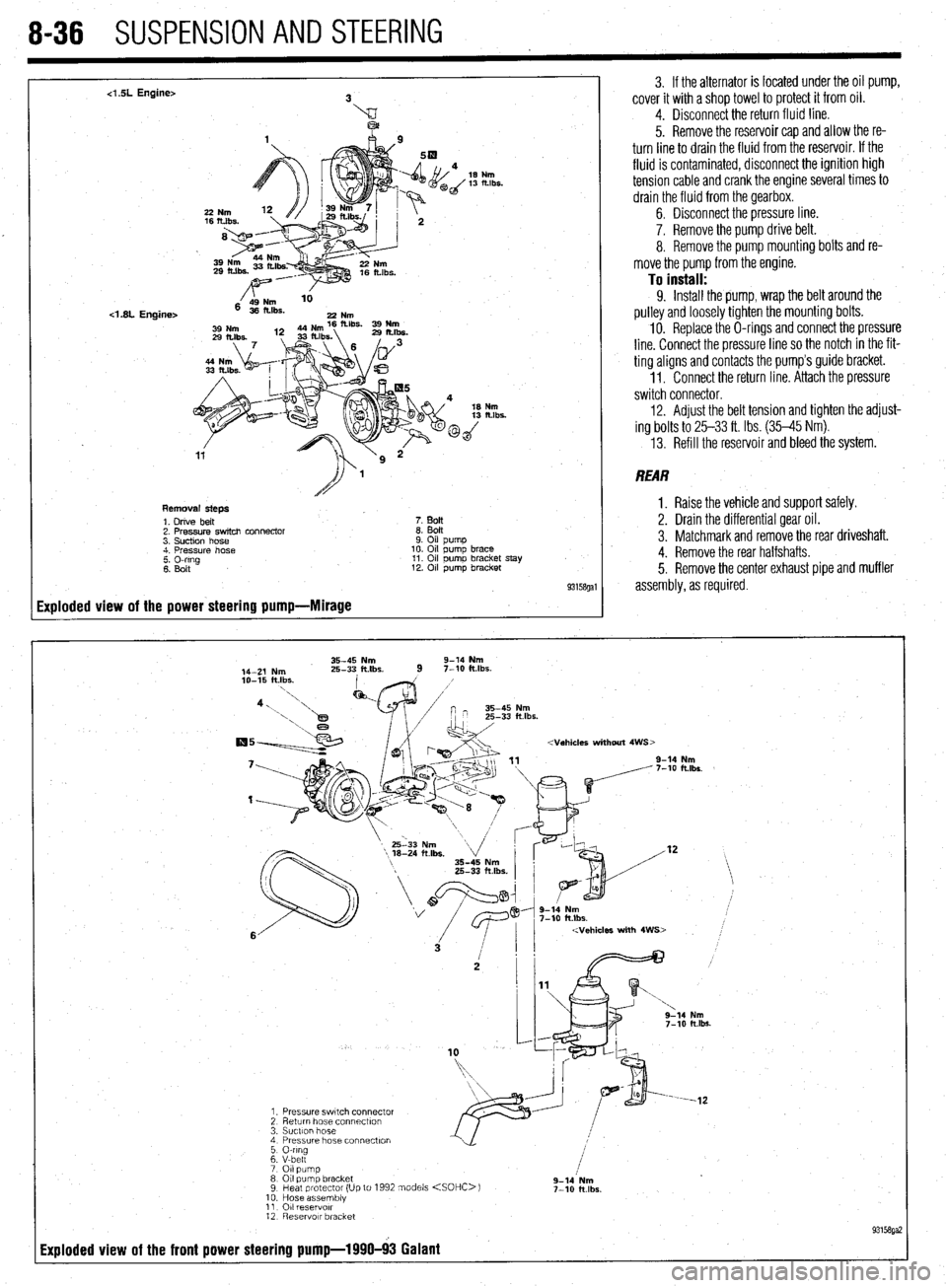
Exploded view of the power steering pump-Mirage
3. If the alternator is located under the oil pump,
cover it with a shop towel to protect it from oil.
4. Disconnect the return fluid line.
5. Remove the reservoir cap and allow the re-
turn line to drain the fluid from the reservoir. If the
fluid is contaminated, disconnect the ignition high
tension cable and crank the engine several times to
drain the fluid from the gearbox.
6. Disconnect the pressure line.
7. Remove the pump drive belt.
8. Remove the pump mounting bolts and re-
move the pump from the engine.
To install: 9. Install the pump, wrap the belt around the
pulley and loosely tighten the mounting bolts.
10. Replace the O-rings and connect the pressure
line. Connect the pressure line so the notch in the fit-
ting aligns and contacts the pump’s guide bracket.
1 I. Connect the return line. Attach the pressure
switch connector.
12. Adjust the belt tension and tighten the adjust-
ing bolts to 25-33 ft. Ibs. (35-45 Nm).
13. Refill the reservoir and bleed the system.
REAR
1. Raise the vehicle and support safely.
2. Drain the differential gear oil.
3. Matchmark and remove the rear driveshaft.
4. Remove the rear halfshafts.
5. Remove the center exhaust pipe and muffler
assembly, as required.
35-45 Nm 9-14 Nm
14-Z Nm 25-33 ft.lbs.
9 7-10 klbs.
2 g-lb Nm
7-10 ft.lbs.
Page 333 of 408

SUSPENSION AND STEERING 8-37
19-28 Nm
14-20 klbs.
/
12-18 Nm
9- 13 ft.lbs.
2rd
,
1. Feed tube
2. O-ring
3. Rear oil pump
4. O-ring
93158ga:
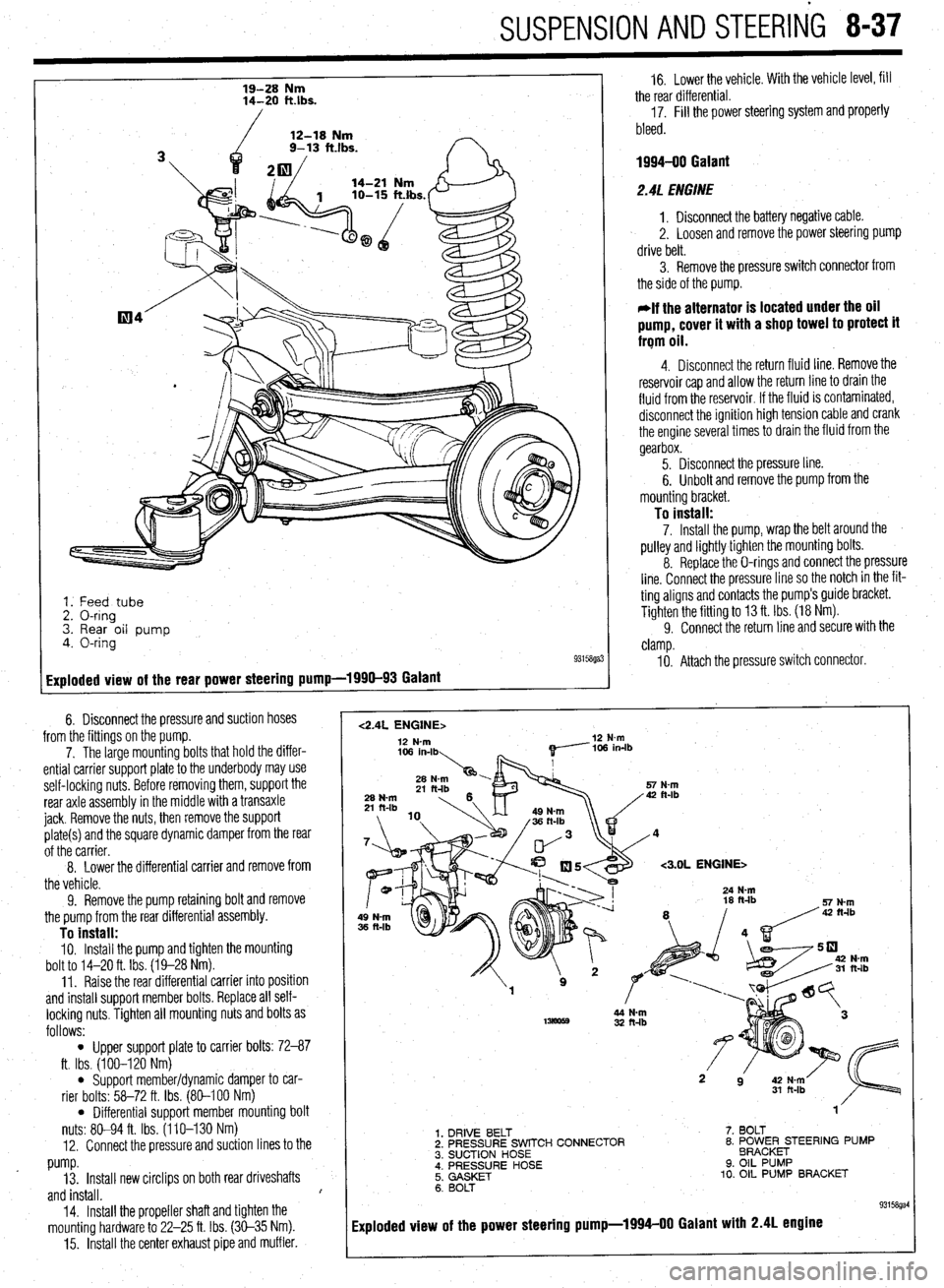
Exploded view of the rear power steering pump-1990-93 Galant
6. Disconnect the pressure and suction hoses
from the fittings on the pump.
7. The large mounting bolts that hold the differ-
ential carrier support plate to the underbody may use
self-locking nuts. Before removing them, support the
rear axle assembly in the middle with a transaxle
jack. Remove the nuts, then remove the support
plate(s) and the square dynamic damper from the rear
of the carrier.
8. Lower the differential carrier
and remove from
the vehicle.
9. Remove the pump retaining bolt and remove
the pump from the rear differential assembly.
To install: IO. Install the pump and tighten the mounting
bolt to 14-20 ft. Ibs. (19-28 Nm).
11. Raise the rear differential carrier into position
and install support member bolts. Replace all self-
locking nuts. Tighten all mounting nuts and bolts as
follows:
l Upper support plate to carrier bolts: 72-87
ft. Ibs. (100-120 Nm)
l Support member/dynamic damper to car-
rier bolts: 58-72 ft. Ibs. (80-100 Nm)
l Differential support member mounting bolt
nuts: 80-94 ft. Ibs. (110-130 Nm)
12. Connect the pressure and suction lines to the
pump.
13. Install new circlips on both rear driveshafts
and install. I
14.
Install the propeller shaft and tighten the
mounting hardware to 22-25 ft. Ibs. (30-35 Nm).
15. Install the center exhaust pipe and muffler.
1
16. Lower the vehicle. With the vehicle level, fill
the rear differential.
17. Fill the power steering system and properly
bleed.
1994-00 Galant
2.4L ENGINE
1. Disconnect the battery negative cable.
2. Loosen and remove the power steering pump
drive belt.
3. Remove the pressure switch connector from
the side of the pump.
*If the alternator is located under the oil
pump, cover it with a shop towel to protect it
frqm oil.
4. Disconnect the return fluid line. Remove the
reservoir cap and allow the return line to drain the
fluid from the reservoir. If the fluid is contaminated,
disconnect the ignition high tension cable and crank
the engine several times to drain the fluid from the
gearbox.
5. Disconnect the pressure line.
6. Unbolt and remove the pump from the
mounting bracket.
To install: 7. Install the pump, wrap the belt around the
pulley and lightly tighten the mounting bolts.
8. Replace the O-rings and connect the pressure
line. Connect the pressure line so the notch in the fit-
ting aligns and contacts the pump’s guide bracket.
Tighten the fitting to 13 ft. Ibs. (18 Nm).
9. Connect the return line and secure with the
clamp.
IO. Attach the pressure switch connector.
<2.4L ENGINE> 12 N-m 12 N-m
<3.OL ENGINE>
32 ft-lb
1. DRIVE BELT
2. PRESSURE SWITCH CONNECTOR
3. SUCTION HOSE
; i’;;‘;;RE HOSE 7. BOLT
8. ~O~~~E;TEER’NG PUMP
9. OIL PUMP
10. OIL PUMP BRACKET
6. BOLT
93158gal
Exploded view of the power steering pump-1994-00 Galant with 2.4L engine
Page 334 of 408

- 8-38 SUSPENSION AND STEERING
11. Adjust the power steering belt for proper ten-
sion and tighten the adjusting bolts.
12. Reconnect the negative battery cable.
13. Refill the reservoir and bleed the system.
3. Of EIJGINE
1. Disconnect the battery negative cable. 2. Disconnect the return fluid line. Remove the
reservoir cap and allow the return line to drain the
fluid from the reservoir. If the fluid is contaminated,
disconnect the ignition high tension cable and crank
the engine several times to drain the fluid from the
gear box.
3. Remove the power steering pump drive belt.
4. Remove the pressure switch connector from
the side of the pump.
5. If the alternator is located under the oil pump,
cover it with a shop towel to protect it from oil.
6. Disconnect the high pressure hose and the
return hose from the pump.
7. Remove the pump drive belt and unbolt the
pump from its bracket and remove the pump.
To install: 8. Install the pump, *rap the belt around the
pulley and tighten the bolts that secure the pump to
17 ft. Ibs. (24 Nm).
9. Replace the O-rings and connect the high
pressure hose. Connect the pressure line so the
notch in the fitting aligns and contacts the pump’s
guide bracket. Tighten the mounting nut with lock-
washer to 17 ft. Ibs. (24 Nm).
IO. Using a new hose clamp, connect the return
line.
11. Attach the pressure switch connector.
12. Adjust the belt tension and tighten the
adjust- ing bolts.
13. Refill the reservoir and bleed the system.
Diamante *
FRONT
. 1. Disconnect the battery negative cable. 2. Disconnect the return fluid line. Remove the
reservoir cap and allow the return line to drain the
fluid from the reservoir. If the fluid is contaminated,
disconnect the ignition high tension cable and crank
the engine several times to drain the fluid from the
gearbox.
3. Remove the power steering pump drive belt.
4. Remove the pressure switch connector from
the side of the pump.
5. If the alternator is located under the oil pump,
cover it with a shop towel to protect it from oil.
6. Disconnect the high pressure hose and the
return hose from the pump.
7. Remove the pump drive belt and unbolt the
pump from its bracket and remove the pump.
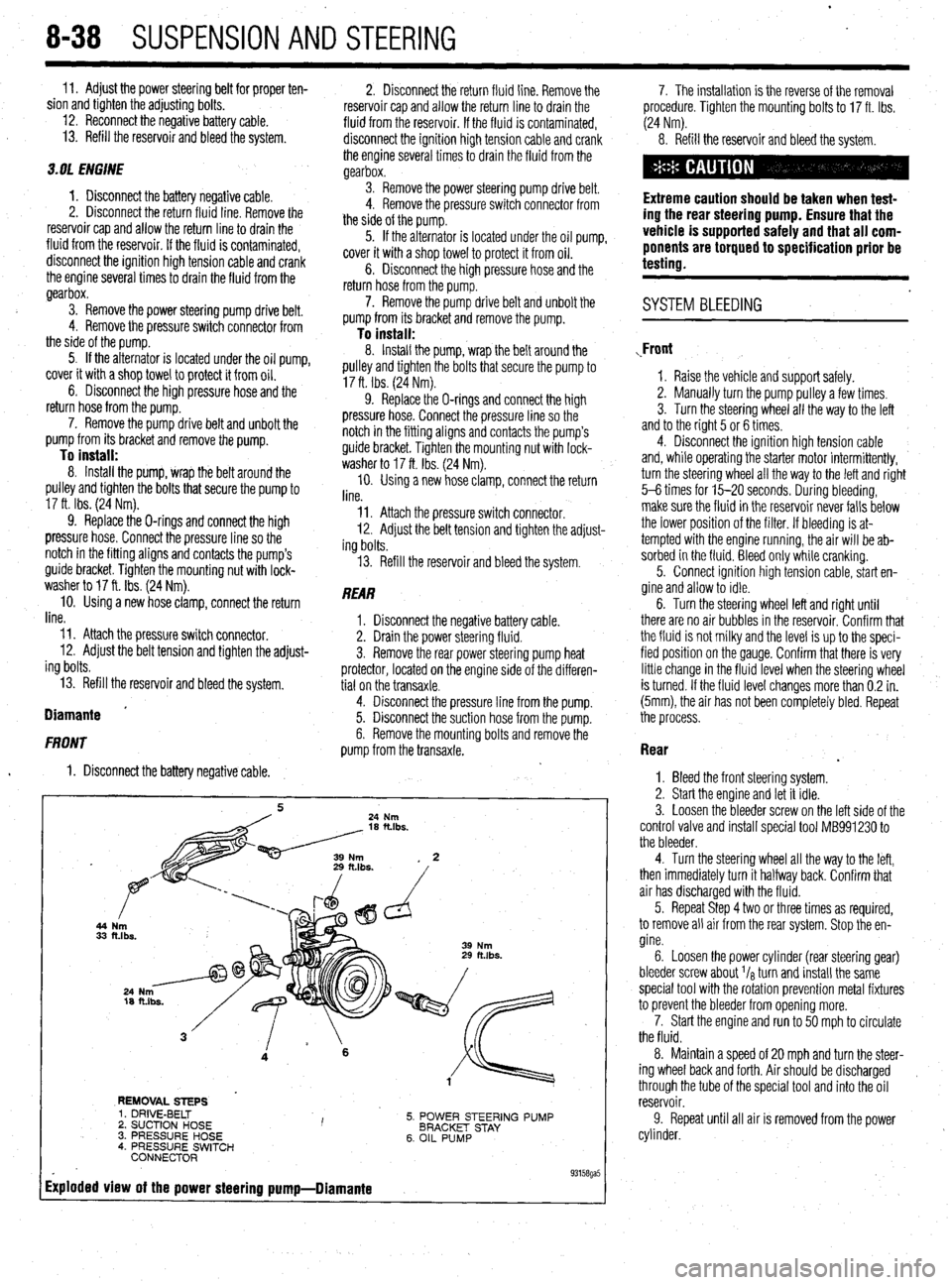
To install: 8. Install the pump, wrap the belt around the
pulley and tighten the bolts that secure the pump to
17 ft. Ibs. (24 Nm).
9. Replace the O-rings and connect the high
pressure hose. Connect the pressure line so the
notch in the fitting aligns and contacts the pump’s
guide bracket. Tighten the mounting nut with lock-
washer to 17 ft. Ibs. (24 Nm).
10. Using a new hose clamp, connect the return
line.
Il. Attach the pressure switch connector.
12. Adjust the belt tension and tighten the adjust-
ing bolts.
13. Refill the reservoir and bleed the system.
REAR
1. Disconnect the negative battery cable.
2. Drain the power steering fluid.
3. Remove the rear power steering pump heat
protector, located on the engine side of the differen-
tial on the transaxle.
4. Disconnect the pressure line from the pump.
5. Disconnect the suction hose from the pump.
6. Remove the mounting bolts and remove the
pump from the transaxle.
44
33
REMOVAL STEPS
5. POWER STEERING PUMP
BRACKET STAY
6. OIL PUMP 1. DRIVE-BELT
2. SUCTION HOSE I ’ 3. PRESSURE HOSE
4. PRESSURE SWITCH
CONNECTOR
Exploded view of the power steering pump-Diamante
. 93158ga5
7. The installation is the reverse of the removal
procedure. Tighten the mounting bolts to 17 ft. Ibs.
(24 Nm).
8. Refill the reservoir and bleed the system.
Extreme caution should be taken when test-
ing the rear steering pump. Ensure that the
vehicle is supported safely and that all com-
ponents are torqued to specification prior be
testing.
. SYSTEM BLEEDING
,Front
1. Raise the vehicle and support safely.
2. Manually turn the pump pulley a few times.
3. Turn the steering wheel all the way to the left
and to the right 5 or 6 times.
4. Disconnect the ignition high tension cable
and, while operating the starter motor intermittently,
turn the steering wheel all the way to the letI and right
5-6 times for 15-20 seconds. During bleeding,
make sure the fluid in the reservoir never falls below
the lower position of the filter. If bleeding is at-
tempted with the engine running, the air will be ab-
sorbed in the fluid. Bleed only while cranking.
5. Connect ignition high tension cable, start en-
gine and allow to idle.
6. Turn the steering wheel left and right until
there are no air bubbles in the reservoir. Confirm that
the fluid is not milky and the level is up to the speci-
fied position on the gauge. Confirm that there is very
little change in the fluid level when the steering wheel
is turned. If the fluid level changes more than 0.2 in.
(5mm), the air has not been completely bled. Repeat
the process.
Rear
.
1. Bleed the front steering system.
2. Start the engine and let it idle.
3. Loosen the bleeder screw on the left side of the
control valve and install special tool MB991230 to
the bleeder.
4. Turn the steering wheel all the way to the left,
then immediately turn it halfway back. Confirm that
air has discharged with the fluid.
5. Repeat Step 4 two or three times as required,
to remove all air from the rear system. Stop the en-
gine.
6. Loosen the power cylinder (rear steering gear)
bleeder screw about I/* turn and install the same
special tool with the rotation prevention metal fixtures
to prevent the bleeder from opening more.
7. Start the engine and run to 50 mph to circulate
the fluid.
8. Maintain a speed of 20 mph and turn the steer-
ing wheel back and forth. Air should be discharged ,
through the tube of the special tool and into the oil
reservoir.
9. Repeat until all air is removed from the power
cylinder.