1900 MITSUBISHI DIAMANTE ABS
[x] Cancel search: ABSPage 3 of 408
GENERALINFORMATIONAND MAINTENANCE l-3
3-19mm, as well as a % in. or ~/a in. spark plug careful when using them, as they can change
socket (depending on plug type). the amount of torque applied to the socket.
-if possible, buy various length socket drive
l Jackstands for support.
extensions. Universal-joint and wobble ex- l Oil filter wrench.
tensions can be extremely useful, but be l Spout or funnel for pouring fluids.
l Grease gun for chassis lubrication (unless
your vehicle is not equipped with any grease fit-
tings-for details, please refer to information on Flu-
ids and Lubricants, later in this section).
l Hydrometer for checking the battery (unless
equiooed with a sealed, maintenance-free batten/).
In addition to the above items there are several O’ A container for draining oil and other fluids.
l Rags for wiping up the inevitable mess.
pi 1 others that are not absolutely necessary, but handy to
have around. These include Oil Dry@ (or an equiva-
lent oil absorbent gravel-such as cat litter) and the
usual SUDDIV of lubricants. antifreeze and fluids. al-
though the.& can be purchased as needed. This is a
basic list for routine maintenance, but only your per-
sonal needs and desire can accurately determine your
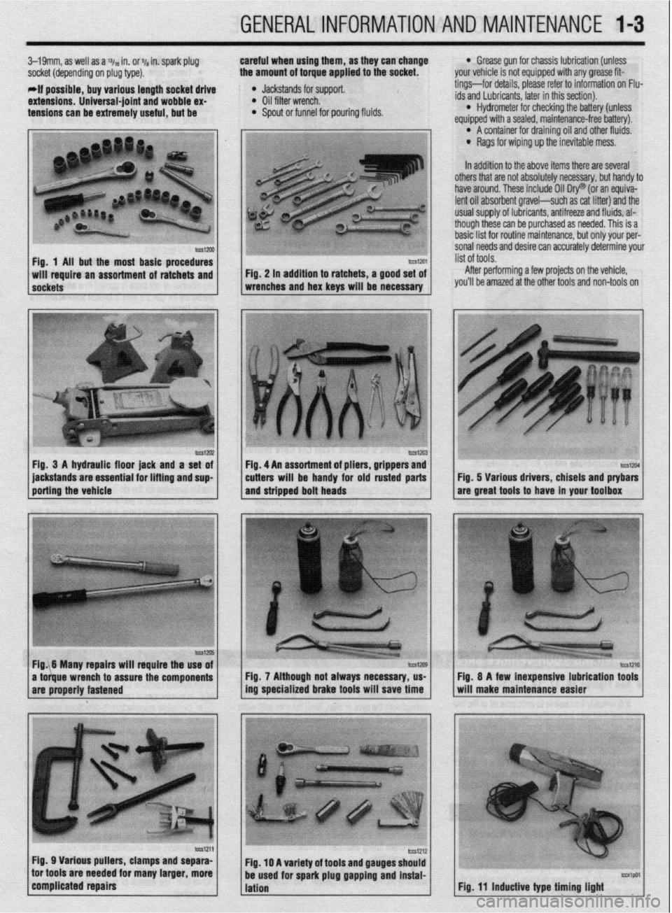
Fig. 1 Ail but the most basic procedures
After performing a few projects on the vehicle,
you’ll be amazed at the other tools and non-tools on
lWSl2U2 Fig, 3 A hydraulic floor jack and a set of
jackstands are essential for lifting and sup
porting the vehicle tm1204 Fig. 5 Various drivers, chisels and ptybars
are great tools to have in your toolbox
Fig. 7 Although not always necessary, us-
ing specialized brake tools will save time
Fig. 11 inductive type timing light
Page 5 of 408
1-6 GENERALINFORMATIONAND MAINTENANCE
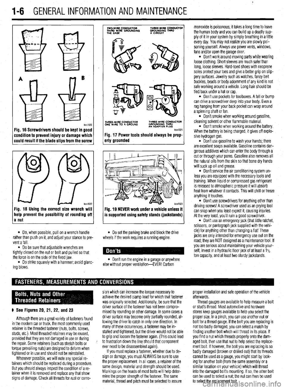
Fig. 16 Screwdrivers should be kept in good
:ondition to prevent injury or damage which
:ould result it the blade slips from the screw
0
0
PP tccs1022 Fig. 16 Using the correct size wrench will
help prevent the possibility of rounding off
a nut
7
lwo.WIRE CouDuClOR TMREE-WIRE CONO”CTOI
MIRD WIRE GROUNDING GROUNDING TNRU
THE CASE A CmxlIT
.
i$Y$$pQ
p-+
TNHREE-WIRE CONDUCTOR THREE-WIRE CONDUCTOR
ONE WIRE TO 4 GROUND GROUNOlNG TMRU
AN ADAPTER PLUG
tccm21
Fig. 17 Power tools should always be prop-
erly grounded
Fig. 19 NEVER work under a vehicle unless it
is supported using safety stands (jackstands)
l Do, when possible, pull on a wrench handle l Do set the parking brake and block the drive
rather than push on it, and adjust your stance to pre-
vent a fall. wheels if the work requires a running engine.
l Do be sure that adjustable wrenches are
tightly closed on the nut or bolt and pulled so that
the force is on the side of the fixed jaw.
l Do strike squarely with a hammer; avoid glanc-
ing blows. l Don’t run the engine in a garage or anywhere
else without proper ventilation-EVER! Carbon monoxide is poisonous; it takes a long time to leave
the human body and you can build up a deadly sup-
ply of it in your system by simply breathing in a !ittle
every day. You may not realize you are slowly poi-
soning yourself. Always use power vents, windows,
fans and/or open the garage door.
l Don’t work around moving parts while wearing
loose clothing. Short sleeves are much safer than
long, loose sleeves. Hard-toed shoes with neoprene
soles protect your toes and give a better grip on slip-
pery surfaces. Jewelry such as watches, fancy belt
buckles, beads or body adornment of any kind is not
safe working around a vehicle. Long hair should be
tied back under a hat or cap.
l Don’t use pockets for toolboxes. A fall or bump
can drive a screwdriver deep into your body. Even a
rag hanging from your back pocket can wrap around
a spinning shaft or fan.
l Don’t smoke when working around gasoline,
cleaning solvent or other flammable material.
l Don’t smoke when workrng around the battery.
When the battery is being charged, it gives off explo-
sive hydrogen gas.
l Don’t use gasoline to wash your hands; there
are excellent soaps available. Gasoline contains dan-
gerous additives which can enter the body through a
cut or through your pores. Gasoline also removes all
the natural oils from the skin so that bone dry hands
will suck up oil and grease.
l Don’t service the air conditioning system un-
less you are equipped with the necessary tools and
trainmg. When liquid or compressed gas refrigerant
is released to atmospheric pressure it will absorb
heat from whatever it contacts. This will chill or freeze
anything it touches.
l Don’t use screwdrivers for anything other than
driving screws! A screwdriver used as an prying tool
can snap when you least expect it, causing injuries.
At the very least, you’ll ruin a good screwdriver.
. Don’t use an emergency jack (that little ratchet,
scissors, or pantograph jack supplied with the vehi-
cle) for anything other than changing a flat! These
jacks are only Intended for emergency use out on the
road; they are NOT designed as a maintenance tool. If
you are serious about mamtaining your vehicle your-
self, invest in a hydraulic floor jack of at least a 1%
ton capacity, and at least two sturdy jackstands.
sion which can increase the torque necessary to proper installation and safe operation of the vehicle
achieve the desired clamp load for which that fastener afterwards.
was originally selected. Additionally, be sure that the Thread gauges are available to help measure a bolt
p See Figures 20, 21, 22, and 23 driver surface of the fastener has not been compro- or stud’s thread. Most automotive and hardware
mised by rounding or other damage. In some cases a stores keep gauges available to help you select the
Although there are a great variety of fasteners found driver surface may become only partially rounded, al- proper size. In a pinch, you can use another nut or
in the modern car or truck, the most commonly used lowing the driver to catch in only one direction. In bolt for a thread gauge. If the bolt you are replacing is
retainer is the threaded fastener (nuts, bolts, screws, many of these occurrences, a fastener may be in- not too badly damaged, you can select a match by
studs, etc.). Most threaded retainers may be reused, stalled and tightened, but the driver would not be able finding another bolt which will thread in its place. If
provided that they are not damaged in use or during to grip and loosen the fastener again. (This could lead you find a nut which threads properly onto the dam-
the repair. Some retainers (such as stretch bolts or J to frustration down the line should that component aged bolt, then use that nut to help select the replace-
torque prevailing nuts) are designed to deform when ever need to be disassembled again). ment bolt If however, the bolt you are replacing is so
tightened or in use and should not be reinstalled. If you must replace a fastener, whether due to de- badly damaged (broken or drilled out) that its threads
Whenever possible, we will note any special re- sign or damage, you must ALWAYS be sure to use cannot be used as a gauge, you might start by look-
tainers which should be replaced during a procedure. the proper replacement In all cases, a retainer of the ing for another bolt (from the same assembly or a
But you should always inspect the condition of a re- same design, material and strength should be used. similar location on your vehicle) which will thread
tainer when It is removed and replace any that show Markings on the heads of most bolts will help deter- into the damaged bolt’s mounting. If so, the other bolt
signs of damage. Check all threads for rust or corro- mine the proper strength of the fastener. The same
can be used to select a nut; the nut can then be used
material, thread and pitch must be selected to assure
to select the replacement bolt.
Page 6 of 408
GENERALINFORMATIONAND MAlNTENAiCE I-7
POZIDRIVE PHILLIPS RECESS
TORX@
CLUTCH RECESS
INDENTED HEXAGON HEXAGON TRIMMED HEXAGON WASHER HEAD
tccs1037
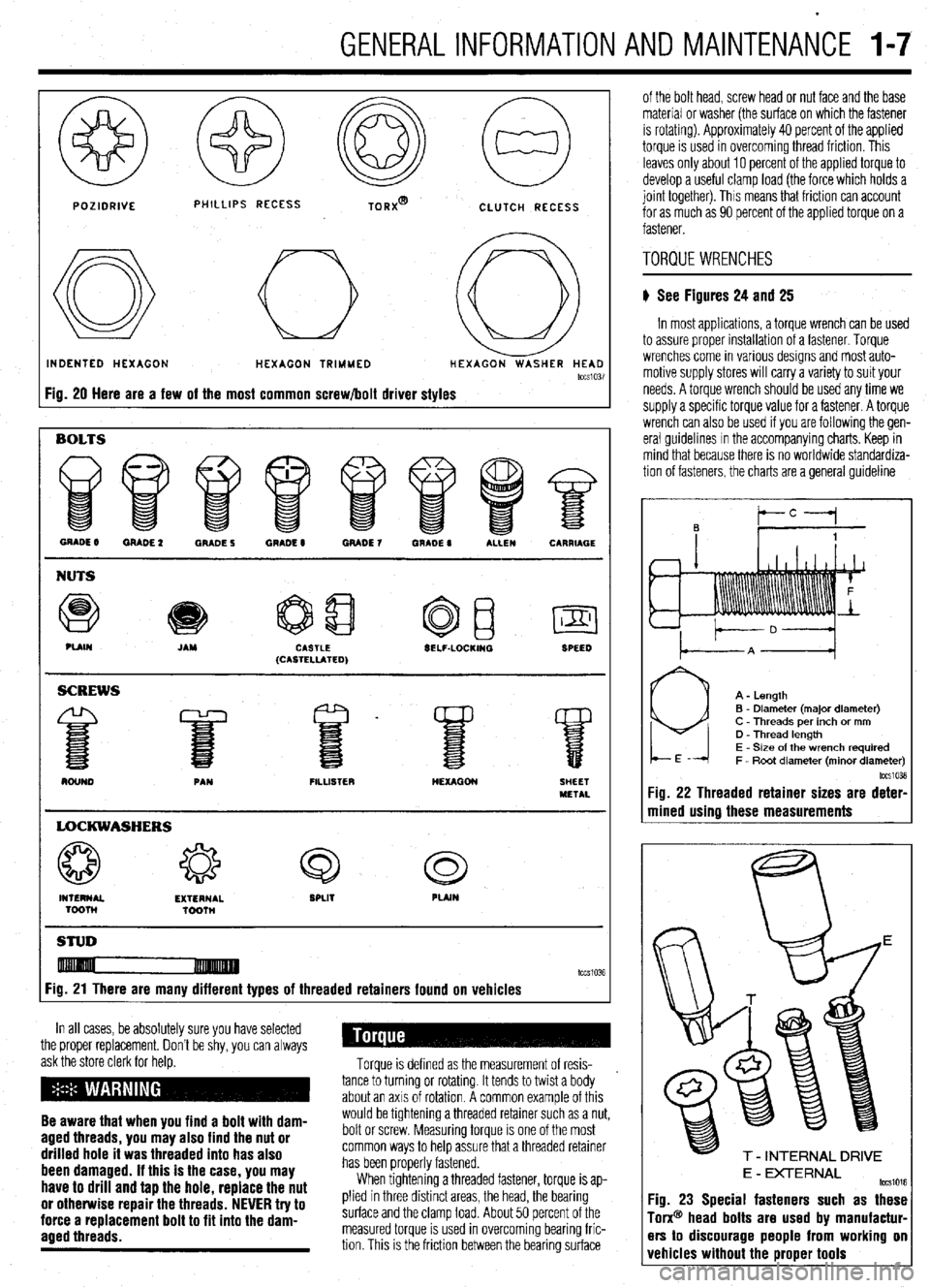
Fig. 20 Here are a few of the most common screw/bolt driver styles
GRADE 8 MADE 2 GRADE 5 QRADE 8 GRADE 7 WADE 0 ALLEN CARRIAGE
NUTS
Q e
PUIN JAM CASTLE
(CASTELLATED) SELF-LOCKINQ
SPEED
FILLISTER
LOCKWASHERS
4% 43 Q c3
INTERNAL EXTERNAL SPLIT PLAIN
Toonl
TQonl
STUD
Fig. 21 There are many different types of threaded retainers found on vehicles
In all cases, be absolutely sure you have selected
the proper replacement. Don’t be shy, you can always
ask the store clerk for helo.
Be aware that when you find a bolt with dam-
aged threads, you may also find the nut or
drilled hole it was threaded into has also
been damaged. If this is the case, you may
have to drill and tap the hole, replace the nut
or otherwise repair the threads. NEVER try to
force a replacement bolt to fit into the dam-
aaed threads.
Torque is defined as the measurement of resis-
.
tance to turning or rotating. It tends to twist a body
about an axis of rotation. A common example of this
would be tightening a threaded retainer such as a nut,
bolt or screw. Measuring torque is one of the most
common ways to help assure that a threaded retainer
has been properly fastened.
When tightening a threaded fastener, torque is ap-
plied in three distinct areas, the head, the bearing
surface and the clamp load. About 50 percent of the
measured torque is used in overcoming bearing fric-
tion This is the friction between the bearing surface of the bolt head, screw head or nut face
and the base
material or washer (the surface on which the fastener
is rotating). Approximately 40 percent of the applied
torque is used in overcoming thread friction. This
leaves only about 10 percent of the applied torque to
develop a useful clamp load (the force which holds a
joint together). This means that friction can account
for as much as 90 percent of the applied torque on a
fastener.
TORQUE WRENCHES
ti See Figures 24 and 25
In most applications, a torque wrench can be used
to assure proper installation of a fastener. Torque
wrenches come in various designs and most auto-
motive supply stores will carry a variety to suit your
needs. A torque wrench should be used any time we
supply a specific torque value for a fastener. A torque
wrench can also be used if you are following the gen-
eral guidelines In the accompanying charts. Keep in
mind that because there is no worldwide standardiza-
tion of fasteners, the charts are a general guideline
A - Length
B - Diameter (major diameter)
C - Threads per inch or mm
D - Thread length
E - Size of the wrench required
F - Root diameter (minor diameter)
IccSlO3l
Fig. 22 Threaded retainer sizes are deter
mined using these measurements
E - DCTERNAL tm1016 Yg. 23 Special fasteners such as these
font@’ head bolts are used by manufactur-
?rs to discourage people from working on
rehicles without the proper tools
Page 7 of 408
.
l-8 GENERALINFORMATIONAND MAINTENANCE
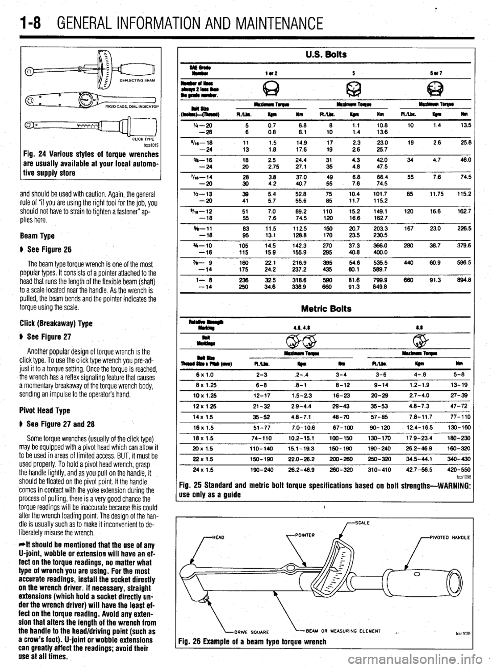
tccsio15 Fig. 24 Various styles of torque wrenches
are usually available at your local automo-
tive supply store
and should be used with caution. Again, the general
rule of “if you are using the right tool for the job, you
should not have to strain to tighten a fastener” ap-
plies here.
Beam Type
# See Figure 26
The beam type torque wrench is one of the most
popular types. It consists of a pointer attached to the
head that runs the length of the flexible beam (shaft)
to a scale located near the handle. As the wrench is
pulled, the beam bends and the pointer indicates the
torque using the scale.
Click (Breakaway) Type
$ See Figure 27
Another popular design of torque wrench IS the
click type. To use the click type wrench you pre-ad-
just it to a torque setting. Once the torque is reached,
the wrench has a reflex signaling feature that causes
a momentary breakaway of the torque wrench body,
sending an impulse to the operator’s hand.
Pivot Head Type
# See Figure 27 and 28
Some torque wrenches (usually of the click type)
may be equipped with a pivot head which can allow it
to be used in areas of limited access. BUT, it must be
used properly. To hold a pivot head wrench, grasp
the handle lightly, and as you pull on the handle, it
should be floated on the pivot point. If the handle
comes in contact with the yoke extension during the
process of pulling, there is a very good chance the
torque readings will be inaccurate because this could
alter the wrench loading point. The design of the han-
dle is usually such as to make it inconvenient to de-
liberately misuse the wrench.
*It should be mentioned that the use of any
U-joint, wobble or extension will have an ef-
fect on the torque readings, no matter what
type of wrench you are using. For the most
accurate readings, install the socket directly
on the wrench driver. If necessary, straight
extensions (which hold a socket directly un-
der the wrench driver) will have the least ef-
fect on the torque reading. Avoid any exten-
sion that alters the length of the wrench from
the handle to the head/driving point (such as
a crow’s foot). U-joint or wobble extensions
can greatly affect the readings; avoid their
use at all times.
U.S. Bolts
UEonlr
Iy*
lU2 5 tw7
I*cll*olwu
Q c
tbqn2lamlu
am~mkr. @ 63
HaaIm Toqw mdmuo TORW
(h&l!&, RA&. m 111 R./U. If410 lm m TolqW
R.Abs.
I(n Hm
'I4 - 20 i 0.7 68 8 1.1 10.8 10 1.4 13.5
-28 08 8.1 10 1.4 13.6
%s-18 11 1.5 14.9 17 2.3 23.0 19 2.6 25.8
-24 13 1.8 17.6 19 2.6 25.7
S-16 18 2.5 24.4 31 4.3 42.0 34 4.7 46.0
-24 20 2.75 27.1 35 4.8 47.5
%s-14 28 3.8 37.0 49 8.8 66.4 55 7.6 74.5
-20 30 42 40.7 55 7.6 74.5
'h-13 39 5.4 52.8 75 10.4 101.7 85 11.75 115.2
-20 41 5.7 55.6 85 117 115.2
'h-12 51 7.0 69.2 110 15.2 149.1 120 16.6 162.7
-18 55 7.6 74.5 120 16.6 162.7
H-11 83 11.5 112.5 150 20.7 203.3 167 23.0 226.5
-18 95 13.1 128.8 170 23.5 230.5
s-10 105 14.5 142.3 270 37.3 366.0 280 36.7 379.6
-16 115 15.9 155.9 295 40.8 400.0
VD- 9 160 2.: 216.9 395 54.6 535.5 440 60.9 596.5
-14 175 237.2 435 80.1 589.7
l- 6 iti 32.5 318.6 lE 81.6 799.9 660 91.3 894.8
-14 34.6 338.9 91.3 849.8
Metric Bolts
4.6,4.8 8.8
c
@ w
mm04 iEn% (nnr) I*rdn*lrTwlr rullllllnl~
RJU.
I(n llm RAk
m mu
6x1.0 2-3 2-.4 3-4 3-6 4-.8 5-8
8x 1.25 6-8 .6-l 8-12 9-14 12-1.9 13-19
10X1.25 12-17 1.5-2.3 16-23 20-29 2.7-4.0 27-39
12x125 21-32 2.9-4.4 29-43 35-53 4.8-7.3 47-72
14x 1.5 35-52 4.8-7.1 48-70 57-65 7.8-11.7 77-110
16x 1.5 51-77 7.0-10.6 67-100 90-120 12.4-16.5 130-W
18x 1.5 74-110 10.2-15.1 100-150 130-170 17.9-23.4 MO-230
20x 1.5 llO-140 15.1-19.3 150-190 190-240 26.2-46.9 160-320
22x 1.5 150-190 22.0-26.2 200-260 250-320 34.5-44.1 340-430
24x 1.5 190-240 26.2-48.9 260-320 310-410 42.7-56.5 420-550
lccs1098 :ig. 25 Standard and metric bolt torque specifications based on bolt strengths-WARNING:
Ise only as a guide
1
PIVOTEO HANDLE
BEAU OR MEASURING ELEMENT
Yg. 26 Example of a beam type torque wrench . tccslo3~
Page 14 of 408
GENERALINFORMATIONAND MAINTENANCE l-15
10. install the air cleaner assembly and the re- *Wrap shop towels around the fitting that is
tainer bolts. being dtsconnected to absorb residual fuel in
11. Connect the air intake hose. the lines. 9. While holding the fuel filter nut with aback-
up wrench, tighten the banjo bolt to 22 ft. Ibs. (30
Nm). Tighten the flare nut to 25 ft. Ibs. (35 Nm), with
12. Attach the solenoid valve.
4. Cover the hose connection with shop towels to a back-up wrench on the nut.
13. Connect the boost hose.
14. Attach the air flow sensor connector. prevent any splash of fuel that could be caused by 10. Tighten the filter mounting bolts to 10 ft. Ibs.
residual pressure in the fuel pipe line. Hold the fuel (14 Nm).
15. Connect the negative battery cable. 11.
filter nut securely with a backup wrench, then remove Connect the negative battery cable. Turn the
REMOVAL &INSTALLATION the banjo bolt on the engine feed line. Disconnect the
high-pressure fuel line from the filter. Remove and
discard the gaskets.
5. While holding the fuel filter nut securely with a
back-up wrench, loosen the filter feed pipe flare nut key to the ON position to pressurize the fuel system
and check for leaks.
12. If repairs of a leak are required, remember to
release the fuel pressure before opening the fuel sys-
tern.
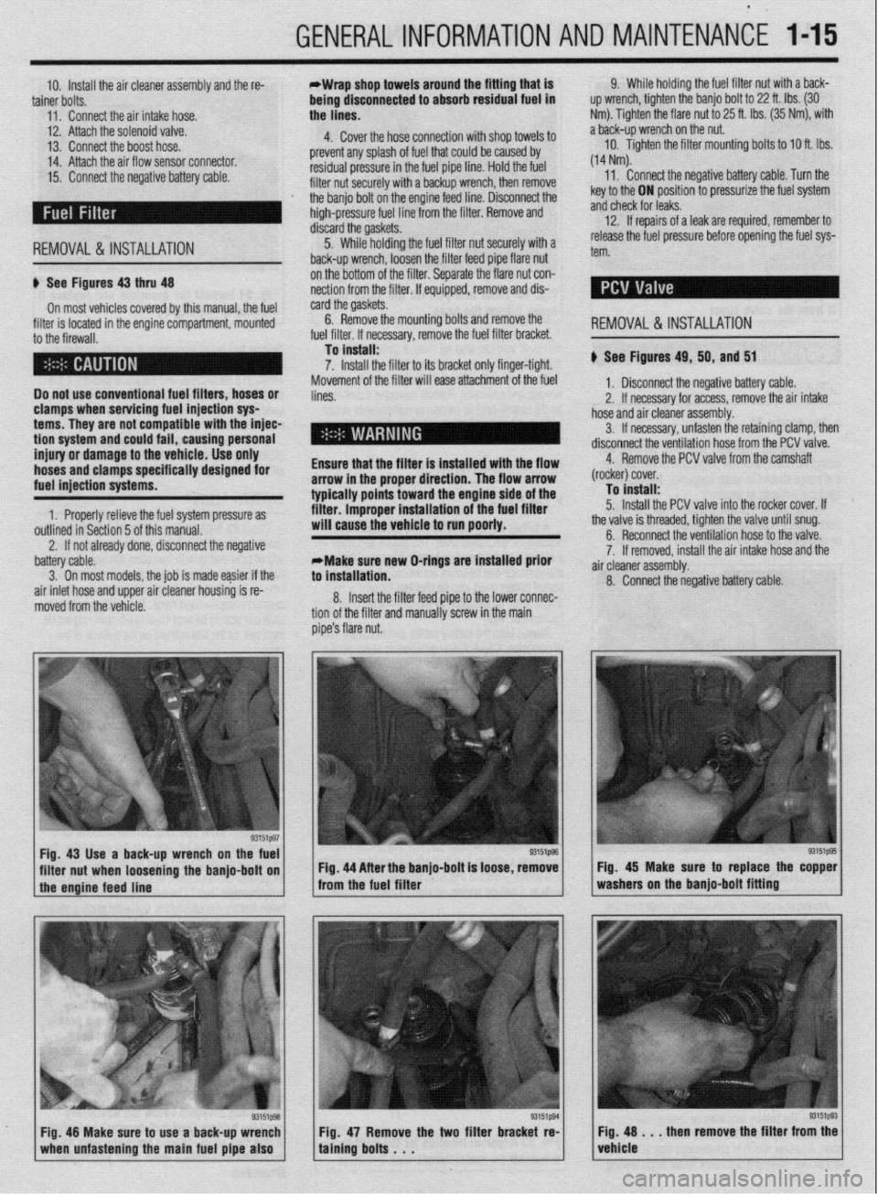
u See Figures 43 thru 48
On most vehicles covered by this manual, the fuel
filter is located in the engine compartment, mounted
to the firewall.
Do not use conventional fuel filters, hoses or
clamps when servicing fuel injection sys
terns. They are not compatible with the injec-
tion
system and could fail, causing personal
injury or damage to the vehicle. Use only
hoses and clamps specifically designed for
fuel injection systems.
1. Properly relieve the fuel system pressure as
outlined in Section 5 of this manual. on the bottom of the filter. Separate the flare nut con-
nection from the filter. If equipped, remove and dis-
card the gaskets.
6. Remove the mounting bolts and remove
. ,,,. ,.
.a r I,.,< I the
ruer rrrter. II necessary, remove me ruer rrrrer oracket.
To install:
7. Install the filter to its bracket only finger-tight.
Movement of the filter will ease attachment of the fuel
lines.
Ensure that the filter is installed with the flow
arrow in the proper direction. The flow arrow
typically points toward the engine side of the
filter. improper installation of the fuel filter
will cause the vehicle to run poorly.
2. If not already done, disconnect the negative REMOVAL&INSTALLATION
u See Figures 49, 50, and 51
1, Disconnect the negative battery cable.
2. If necessary for access, remove the air intake
hose and air cleaner assembly.
3. If necessary, unfasten the retaining clamp, then
disconnect the ventilation hose from the PCV valve.
4. Remove the PCV valve from the camshaft
(rocker) cover.
To install:
5. Install the PCV valve into the rocker cover. If
the valve is threaded, tighten the valve until snug.
battery cable.
3. On most models. the iob is made easier if the
air inlet hose and upper air cleaner housing is re-
moved from the vehicle. *Make sure new O-rings are installed prior
to installation.
8. Insert the filter feed pipe to the lower connec-
tion of the filter and manually screw in the main
pipe’s flare nut. 6. Reconnect the ventilation hose to the valve.
7. If removed, install the air intake hose and the
a .ir cleaner assembly.
8. Connect the negative battery cable.
Fig. 43 Use a back-up wrench on the fuel
I I
93151@3
filter nut when loosening the banjo-bolt on Fig. 44 After the banjo-bolt is loose, remove
I
1 the engine feed line - from the fuel filter
93151p93 Fig. 48 Make sure to use a back-up wrench
1 when unfastening the main fuel pipe also 1 Fig. 47 Remove the two filter bracket re-
taining bolts . . . Fig. 45 Make sure to replace the copper
washers on the banjo-bolt fitting
Fig. 48 . . . then remove the filter from the
vehicle
Page 21 of 408
l-22 GENERALINFORMATIONAND MAINTENANCE
tears. If the boot is damaged, it should be replaced
trode is to the block’s cooling passages) the cooler it
your driving is long distance, high speed travel, use a
immediately. Please refer to Section 7 for procedures.
will operate. A plug that absorbs little heat and re-
colder plug; if most of your driving is stop and go,
mains too cool will quickly accumulate deposits of
use a hotter plug. Original equipment plugs are gen-
oil and carbon since it is not hot enough to burn
erally a good compromise between the 2 styles and
them off. This leads to plug fouling and consequently
most people never have the need to change their
to misfiring. A plug that absorbs too much heat will
plugs from the factory-recommended heat range.
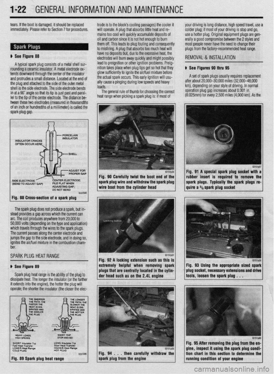
ti See Figure 88 have no deposits but, due to the excessive heat, the
,electrodes will burn away quickly and might possibly
REMOVAL &INSTALLATION
A typical spark plug consists of a metal shell sur- lead to preignition or other ignition problems. Preig-
rounding a ceramic insulator. A metal electrode ex- nition takes place when plug tips get so hot that they
ti See Figures 90 thru 95
tends downward through the center of the insulator glow sufficiently to ignite the air/fuel mixture before
and protrudes a small distance. Located at the end of the actual spark occurs. This early ignition will usu- A set of spark plugs usually requires replacement
the plug and attached to the side of the outer metal ally cause a pinging during low speeds and heavy after about 20,000-30,000 miles (32,000-48,000
shell is the side electrode. The side electrode bends loads. km), depending on your style of driving. In normal
in at a 90” angle so that its tip is just past and paral- The general rule of thumb for choosing the correct operation plug gap increases about 0.001 in.
lel to the tio of the center electrode. The distance be- heat range when picking a spark plug is: if most of (0.025mrn) for every 2,500 miles
(4,000 km). As the
tween these two electrodes (measured in thousandths
of an inch or hundredths of a millimeter) is called the
spark piug gap.
The spark plug does not produce a spark, but in-
steed provides a gap across which the current can
arc. The coil produces anywhere from 20,000 to
50,000 volts (depending on the type and application)
which travels through the wires to the spark plugs.
The current passes along the center electrode and
jumps the gap to the side electrode, and in doing so,
ignites the air/fuel mixture in the combustion charn-
ber.
SPARKPLUG HEATRANGE
ti See Figure 89
Spark plug heat range is the ability of the plug to
dissipate heat. The longer the insulator (or the farther
INSULATOR CRACKS
OFTEN OCCUR HERE
SIDE ELECTRODE ENTER ELECTRODE:
(SEND TO ADJUST GAP) FILE FLAT WHEN
ADJUSTING GAP;
DO NOT BEND
Fig. 88 Cross-section of a spark plug
it extends into the engine), the hotter the plug will
operate; the shorter the insulator (the closer the elec- Fig. 90 Carefully twist the boot end of the
I
spark plug wire and withdraw the spark plug
wire boot from the cylinder head
Fig. 92 A locking extension such as this is
extremely helpful when removing spark
plugs that are centrally located in the cyhn-
Fig. 94 . . .
then carefully withdraw the
spark plug from the engine Fig. 91 A special spark plug socket with a
rubber insert is required to remove the
spark plugs. Typically the spark plugs
re-
quire a Ya spark plug socket
Fig, 93 Using the appropriate sized spark
plug socket, necessary extensions and drive
tools, loosen the spark plug . . .
93151ptxl Fig. 95 After removing the plug from the en-
gine, inspect it using the spark plug condi-
tion chart in this section to determine the
running condition of your engine
Page 23 of 408
l-24 GENERALINFORMATIONAND MAINTENANCE
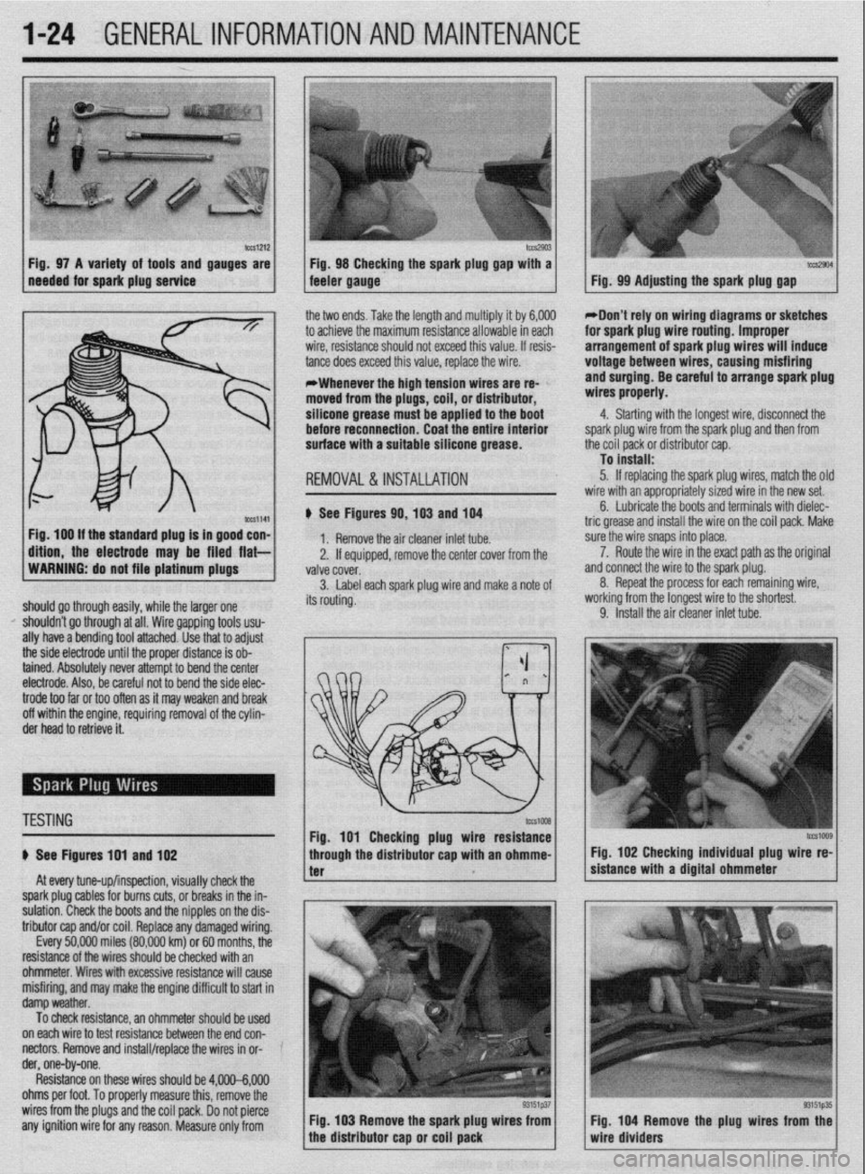
b%slZl2 Fig. 97 A variety of tools and gauges are
needed for spark plug service tm2903 Fig. 98 Checking the spark plug @au with a tccs2904 feeler gauge. - Fig. 99 Adjusting the spark plug gap
ig. 100 If the standard plug Is in good con-
ftlon, the electrode may be filed flat- the two ends. Take the length and multiply it by 6,000
to achieve the maximum resistance allowable in each
wire, resistance should not exceed this value. If resis-
tance does exceed this value, replace the wire.
*Whenever the high tension wires are re- ’
moved from the plugs, coil, or distributor,
silicone grease must be applied to the boot
before reconnection. Coat the entire Interior
surface with a suitable silicone grease.
REMOVAL &INSTALLATION
# See Figures 90,103 and 104
1. Remove the air cleaner inlet tube.
2. If eouiooed, remove the center cover from the
WARNING: do not file platinum plugs
valve covei.
3. Label each spark plug wire and make a note of
should go through easily, while the larger one its routing.
I’ shouldn’t go through at all. Wire gapping tools usu-
ally have a bending tool attached. Use that to adjust
the side electrode until the proper distance is ob-
tained. Absolutely never attempt to bend the center
electrode. Also, be careful not to bend the side elec- *Don’t rely on wiring diagrams or sketches
for spark plug wire routing. Improper
arrangement of spark plug wires will induce
voltage between wires, causing misfiring
and surging. Be careful to arrange spark plug
wires properly.
4. Starting with the longest wire, disconnect the
spark plug wire from the spark plug and then from
the coil pack or distributor cap.
To install:
5. If replacing the spark plug wires, match the olc
wire with an appropriately sized wire in the new set.
6. Lubricate the boots and terminals with dielec-
tric grease and install the wire on the coil pack. Make
sure the wire snaps into place.
a 7. Route the wire in the exact path as the original
nd connect the wire to the spark plug.
8. Repeat the process for each remaining wire,
iorking from the longest wire to the shortest.
9. Install the air cleaner inlet tube.
trode too far or too often as it may weaken and break
off within the engine, requiring removal of the cylin-
der head to retrieve it.
TESTING
# See Figures 191 and 102
At every tune-up/inspection, visually check the
spark plug cables for burns cuts, or breaks in the in-
sulation. Check the boots and the nipples on the dis-
tributor cap and/or coil. Replace any damaged wiring.
Every 50,000 miles (80,000 km) or 60 months, the
resistance of the wires should be checked with an
ohmmeter. Wires with excessive resistance will cause
misfiring, and may make the engine difficult to start in
damp weather.
To check resistance, an ohmmeter should be used ’
on each wire to test resistance between the end con-
nectors. Remove and install/replace the wires in or- ’
der, one-by-one.
Resistance on these wires should be 4,000-6,000
ohms per foot. To properly measure this, remove the
wires from the plugs and the coil pack. Do not pierce
any ignition wire for any reason. Measure only from Fig. 103 Remove the spark plug wires from
tcG1009 Fig. 102 Checking individual plug wire re-
sistance with a digital ohmmeter
Fig. 104 Remove the plug wires from the
wire dividers
Page 29 of 408
.
l-30 GENERAL'INFORMATIONAND MAINTENANCE
n Pylon@ inserts, the clip
be removed prior to siidi then the insert can be re
After installing the replacement
strip and pull up while twisting counterclockwise.
The backing strip will snap out of the retaining tab.
Do this for the remaining tabs until the refill is free of
the blade. The length of these refills is molded into
the end and they should be replaced with identical
types. cate the front end is out of alignment or that the tires
are out of balance.
TIRE ROTATION
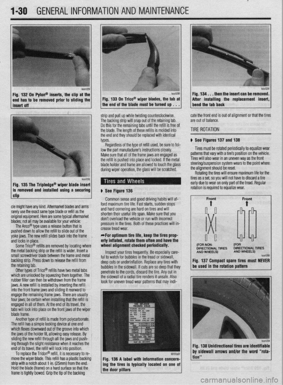
# See Figures 137 and 138
Tires must be rotated periodically to equalize wear
patterns that vary with a tire’s position on the vehicle.
Tires will also wear in an uneven way as the front
1 Fin 1% Tha Trinlarlna@
cle might have any kind. Aftermarket blades and arms
rarely use the exact same type blade or refill as the
original equipment. Here are some typiel aftermarket
blades; not all may be available for your vehicle:
The Anco@ type uses a release button that is
pushed down to allow the refill to slide out of the
yoke jaws. The new refill slides back into the frame
,
and locks in place.
Some Trico@ refills are removed by locating where
the metal backing strip or the refill is wider. Insert a
small screwdriver blade between the frame and metal
backing strip. Press down to release the refill from
the retaining tab.
Other types of Trico@’ refills have two metal tabs
which are unlocked by squeezing them together. The
rubber filler can then be withdrawn from the frame
iaws. A new refill is installed bv insertina the refill lowed to touch the olass steering/suspension system wears to the point where
the alianment should be reset.
# See Figure 138
Common sense and good driving habits will af-
ford maximum tire life. Fast starts, sudden stops
and hard cornering are hard on tires and will
shorten their useful life span. Make sure that you
don’t overload the vehicle or run with incorrect
pressure in the tires. Both of these practices will in-
crease tread wear.
*For optimum tire life, keep the fires prop
eriy inflated, rotate them often and have the
wheel alignment checked periodically.
Inspect your tires frequently. Be especially care-
ful to watch for bubbles in the tread or sidewall,
deep cuts or underinflation. Replace any tires with
bubbles in the sidewall. If cuts are so deep that they
penetrate to the cords, discard the tire. Any cut in
the sidewall of a radial tire renders it unsafe. Also
look for uneven tread wear patterns that may indi- Rotating the tires will ensure maximum life for the
tires as a set, so you will not have to discard a tire
early due to wear on only part of the tread. Regular
DIRECTIONAL TIRES DIRECTIONAL TIRES
jnto the front frame jaws and &ding it rearward to
engage the remaining frame jaws. There are usually
four jaws; be certain when installing that the refill is
engaged in all of them. At the end of its travel, the
tabs will lock into place on the front jaws of the wiper
blade frame.
Another type of refill is made from polycarbonate.
The refill has a simple locking device at one end
which flexes downward out of the groove into which
the jaws of the holder fit, allowing easy release. By
sliding the new refill through all the jaws and push-
ing through the slight resistance when it reaches the
end of its travel, the refill will lock into position.
To replace the Tridon@ refill, it is necessary to re-
move the wiper blade. This refill has a plastic backing
strip with a notch about 1 in. (25mm) from the end.
Hold the blade (frame) on a hard surface so that the
frame is tightly bowed. Grip the tip of the backing Fig. 138 A label with information concern-
ing the tires is typically located on one of
the door pillars
tion”