1900 MITSUBISHI DIAMANTE ABS
[x] Cancel search: ABSPage 40 of 408
.
GENERALINFORMATIONAND MAINTENANCE l-41
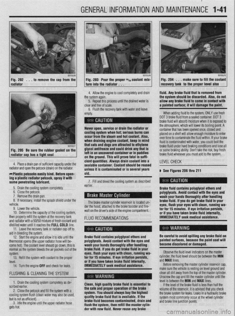
93151p18 Fig. 202 . , . to remove the cap from the
radiator
93151p17 Fig. 205 Be sure the rubber gasket on the
radiator cap has a tight seal e Fig. 203 Pour the proper *I~ coolant mix- 1 Fig. 204 . . . make sure to fill the coolant
recovery tank to the proper level also ture into the radiator . . .
.I
4. Allow the engine to cool completely and drain fluid. Any brake fluid that is removed from
ie system again.
5. Repeat this processuntil the drained water is
lear
and free of scale.
6. Flush the recovery tank with water and leave ’
mpty. the system should be discarded. Also, do not
allow any brake fluid to come in contact with
a painted surface; it will damage the paint.
When adding fluid to the system, ONLY use fresh
DOT 3 brake fluid from a sealed container. DOT 3
brake fluid will absorb moisture when it is exposed to
.a . . . , .*a. . . * .*. . .
- Never open, service or drain the radiator or
cooling system when hot; serious bums can
occur from the steam and hot coolant. Also,
when draining engine coolant, keep In mind
that cats and dogs are attracted to ethylene
glycol antifreeze and could drink any that is
left in an uncovered container or in puddles
on the ground. This will prove fatal in suffi-
4. Place a drain pan of suff i ’ 1 . . . ..I .I. 1,~ cient quantities. Always tne atmospnere, wnrcn wnr rower 1r.s oourng pomr. A
container that has been opened once, closed and
placed on a shelf will allow enough moisture to enter
over time to contaminate the fluid within. If your brake
fluid is contaminated with water, you could boil the
brake fluid under hard braking conditions and lose all
or some braking ability. Don’t take the risk, buy fresh
brake fluid whenever you must add to the system.
crenr capacrry unaer me
drain) on the radiator.
rrrasuc perwcss easuy bind; Before open-
ing a plastic radiator petcock, spray it with
some penetrating lubricant. drain coolant into a
earner. sealable container. Coolant should be reused
unless it is contaminated or is several years
old.
The brake master cylinder ~a~~~~r,~~ :A I~nnL.4 n-n 7. Fill and bleed the cooling system as described
Brake fluid contains polyglycol ethers and
polyglycols. Avoid contact with the eyes and ,LEVEL CHECK
wash your hands thoroughly after handling
brake fluid. If vou do oet brake fluid in vour
eyes, flush your eyeswith clean, runniug wa-
a-.. ‘Y-- ar -l-..n-- II -.._ I____ k See Figures 206 thru 211
.a-11-- - __-PA._ radiator and open the petcock (
- w&1--x3_ --mm.._..- . . ..-I...
5. Drain the cooling system completely.
6. Close the petcock.
7. Remove the drain pan.
If necessary, install the splash shield under the 8.
L.-l
venicie.
9. Lower the vehicle.
10. Determine the capacity of the cooling system,
then properly refill the system at the recovery tank
and radiator with a 50/50 mixture of fresh coolant and
fKm”“ll 15 IUMLC” “II- brake booster and fire- der the hood, attached to the
wall on the drivers side of the engine compartment.
FLUID RECOMMENDATIONS rer mr 13 mmures. IT eye irriIauon persim, or if you have taken brake fluid internally,
IMMEDIATELY seek medical assistance.
ala in oreerring me sysrem.
12. Start the engine and allow it to idle until the
thermostat opens (the upper radiator hose will be-
come hot). The coolant level should go down, this is
normal as the system bleeds the air pockets out of the
svstem.
IRVf!l ._._. 14. Turn the engine OFF and check for leaks. IMMEDIATELY seek medical assistance.” Brake fluid contains polyglycol ethers and
polyglycols. Avoid contact with the eyes and
wash your hands thoroughly after handling
brakefluid. If you do get brake fluid in your
eyes, flush your eyes with clean, running wa-
or if vou have taken brake fluid internallv.
Before removing the master cylinder reservoir cap,
make sure the vehicle is resting on level ground and Be careful to avoid spilling any brake fluid on
painted surfaces, because the paint coat will
become discolored or damaged.
Observe the fluid level indicators on the master
._ ._ __
‘eve1 should be between the MIN
ano
ivw unes. 13. Refill the system with coolant to the proper ter for 15 minutes; If eye irritation persists, cylinder; the tluld II
..J ..I” I....
FLUSHING & CLEANINGTHE SYSTEM
1. Drain the cooling system completely as de:
scribed earlier.
2. Close the petcock and fill the system with a
cooling system flush (clean water may also be used,
but is not as efficient).
3. Idle the engine until the upper radiator hose
gets hot. Clean, high quality brake fluid is essential to
the safe and proper operation of the brake
system. You should always buy the highest
quality brake fluid that is available. If the
brake fluid becomes contaminated, drain and
flush the system, then refill the master cylin-
der with new fluid. Never reuse any brake clean all dirt away from the top of the master cylinder.
Unscrew the cap and fill the master cylinder until the
level is between the MIN and MAX lines.
If the level of the brake fluid is less than half the
volume of the reservoir, it is advised that you check
the brake system for leaks. Leaks in a hydraulic brake
system most commonly occur at the wheel cylinder
and brake line junction points.
Page 72 of 408
.
ENGINEAND,ENGINEOVERHAUL 3-11
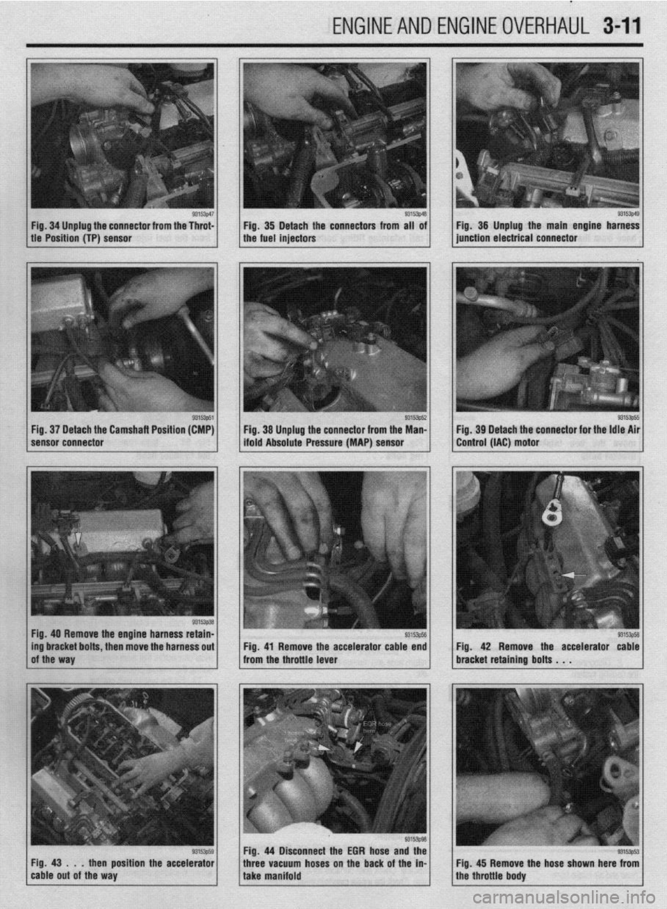
Fig. 34 Unplug the connector from the Throt-
tle Position (TP) sensor Fig. 35 Detach the connectors from all of
the fuel injectors
93wp3a Fig. 40 Remove the engine harness retain-
ing bracket bolts, then move the harness out
of the way Fig. 38 Unplug the connector from the Man-
ifold Absolute Pressure (MAP) sensor 93153p5a Fig. 41 Remove the accelerator cable end
from the throttle lever
93153p59 Fig. 43 . . . then position the accelerator
cable out of the way
93i53p9a Fig. 44 Disconnect the EGR hose and the
three vacuum hoses on the back of the in- take manifold Fig. 39 Detach the connector for the Idle Air
Control (IAC) motor
93153p5a Fig. 42 Remove the accelerator cable
bracket retaining bolts . . .
93153p53 Fig. 45 Remove the hose shown here from
the throttle body
Page 89 of 408
3-28 ENGINEANDENGINEOVERHAUL
lntsltaelde Front of engine c3
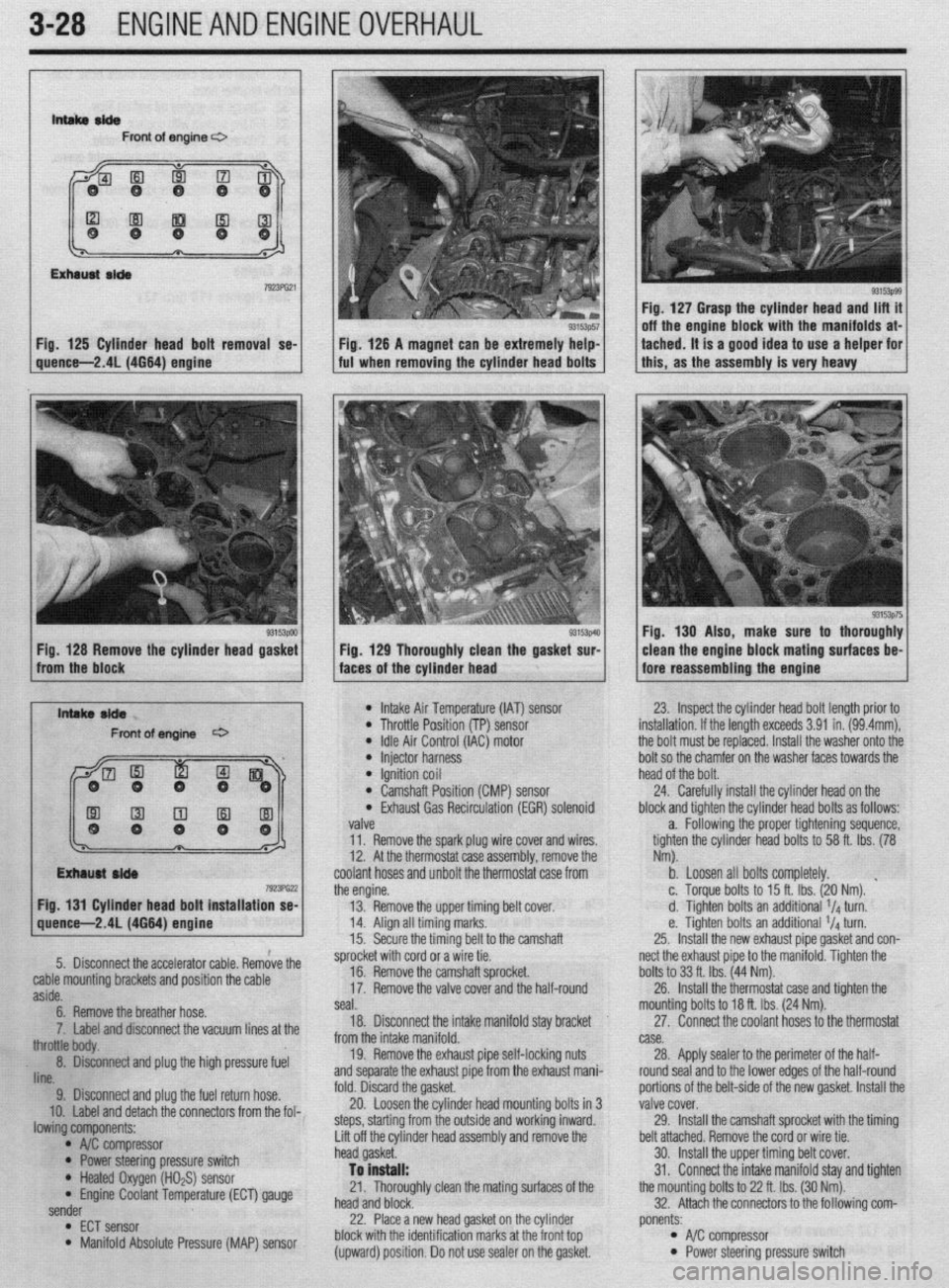
Fig. 125 Cylinder head bolt removal se- Fig. 127 Grasp the cylinder head and lift it
off the engine block with the manifolds at-
ig. 126 A magnet can be extremely help- tached. It is a good idea to use a helper for
quence-2.41(4664) engine I ful when removing the cylinder head bolts 1 1 this, as the assembly is very heavy
93153pOO Fig. 128 Remove the cylinder head gasket 33153p4!3 Fig, 129 Thoroughly clean the gasket sur- Fig. 130 Also, make sure to thoroughly
clean the engine block mating surfaces be-
from the block
faces of the cylinder head fore reassembling the engine
l Intake Air Temperature (IAT) sensor l Throttle Position (TP) sensor
: /I;%;,; rZ;Z;;(lAC) motor 23. Inspect the cylinder head bolt length prior to
installation. If the length exceeds 3.91 in. (99.4mm),
the bolt must be replaced. Install the washer onto the
bolt so the chamfer on the washer faces towards the
l Ignition coil head of the bolt. l Camshaft Position (CMP) sensor 24. Carefully install the cylinder head on the l Exhaust Gas Recirculation (EGR) solenoid block and tighten the cylinder head bolts as follows:
valve a. Following the proper tightening sequence,
11. Remove the spark plug wire cover and wires. tighten the cylinder head bolts to 58 ft. Ibs. (78
12. At the thermostat case assembly, remove the Nm).
coolant hoses and unbolt the thermostat case from b. Loosen all bolts completely.
the engine. c. Torque bolts to 15 ft. Ibs. (20 Nm). ’
Fig. 131 Cylinder head bolt installation se-
13. Remove the upper timing belt cover d. Tighten bolts an additional 1/4 turn.
14. Align all timing marks. e. Tighten bolts an additional 1/4 turn.
15. Secure the timina belt to the camshaft 25. Install the new exhaust pipe aasket and con-
iliiL.-
5.
9. Disconnect and plug the fuel return hose. Disconnect the accelerator cable. Remove the
cable mounting brackets and position the cable
10. Label and detach the connectors from the fol- aside.
lowing components: 6. Remove the breather hose.
* A$ compressor
* Power steering pressure switch ‘7. Label and disconnect the vacuum lines at the
* Heated Oxygen (HO$) sensor tree body.
* Engine Coolant Temperature (ECT) gauge . 8. D&connect and plug the high pressure fuel
sender
lint3
l
ECT sensor l Manifold Absolute Pressure (MAP) sensor sprocket with cord or a wire tie.
fold. Discard the gasket, 16. Remove the camshaft sprocket.
20. Loosen the cylinder head mounting bolts in 3 17.
steps, starting from the outside and working inward. Remove the valve cover and the half-round
seal.
Lift off the cylinder head assembly and remove the 18. Disconnect the intake manifold stay bracket
head gasket.
To install: from the intake manifold.
21. Thoroughly clean the mating surfaces of the 19. Remove the exhaust pipe self-locking nuts
head and block. and separate the exhaust pipe from the exhaust mani-
22. Place a new head gasket on the cylinder
block with the identification marks at the front top
(upward) position. Do not use sealer on the gasket. nect the exhaust pipe to the manifold. Tighten the
portions of the belt-side of the new gasket. Install thr bolts to 33 ft. Ibs. (44 Nm).
valve cover. 26.
29. Install the thermostat case and tighten the
Install the camshaft sprocket with the timing mounting bolts to 18 ft. Ibs. (24 Nm).
belt attached. Remove the cord or wire tie.
30. Install the upper timing belt cover. 27. Connect the coolant hoses to the thermostat
31. Connect the intake manifold stay and tighten case.
the mounting bolts to 22 ft. Ibs. (30 Nm). 28.
32. Attach the connectors to the following com- Apply sealer to the perimeter of the half-
round seal and to the lower edges of the half-round
ponents: l A/C compressor l Power steering pressure switch
Page 144 of 408
EMISSION CONTROLS 4-2
CRANKCASEVENTILATIONSYSTEM 4-2
OPERATION 4-2
COMPONENTTESTING 4-2
REMOVAL &INSTALLATION 4-2
EVAPORATIVEEMISSIONCONTROLS 4-2
OPERATION 4-2
COMPONENTTESTING 4-3
REMOVAL&INSTALLATION 4-4
EXHAUSTGASRECIRCULATION
SYSTEM 4-5
OPERATION 4-5
COMPONENTTESTING 4-5
REMOVAL&INSTALLATION 4-6
ELECTRONIC ENGINE CONTROLS 4-7
ENGlNECONTROLUNIT/POWERTRAIN
CONTROLMODULE(ECU/PCM) 4-7
OPERATION 4-7
REMOVAL&INSTALLATION 4-7
OXYGENSENSOR 4-8
OPERATION 4-8
TESTING 4-8
REMOVAL&INSTALLATION 4-8
IDLEAIRCONTROLMOTOR 4-9
OPERATION 4-9
TESTING 4-9
REMOVAL&INSTALLATION 4-9
ENGINECOOLANTTEMPERATURE
SENSOR 4-10
OPERATION 4-10
TESTING 4-10
REMOVAL&INSTALLATION 4-10
INTAKEAIRTEMPERATURESENSOR 4-10
OPERATION 4-10
TESTING 4-11
REMOVAL&INSTALLATION 4-11
MASSAIRFLOWSENSOR 4-11
OPERATION 4-11
TESTING 4-11
REMOVAL&INSTALLATION 4-11
MANIFOLDABSOLUTEPRESSURE
SENSOR 4-12
OPERATION 4-12
TESTING 4-12
REMOVAL&INSTALLATION 4-13
THROTTLEPOSITIONSENSOR 4-13
OPERATION 4-13
TESTING 4-13
REMOVAL&INSTALLATION 4-13
CAMSHAFT POSITIONSENSOR 4-14
OPERATION 4-14
TESTING 4-14
REMOVAL&INSTALLATION 4-14
CRANKSHAFTPOSlTlONSENSOR/CRANK
ANGLE SENSOR 4-14
OPERATION 4-14 I
TESTING 4-15 REMOVAL&INSTALLATION 4-15
COMPONENT LOCATIONS 4-16
OBD-1 TROUBLE CODES 4-26
GENERALINFORMATION 4-26
CHECKENGINVMALFUNCTION
INDICATOR LIGHT 4-26
SERVICEPRECAUTIONS 4-26
READING CODES 4-26
WITHASCANTOOL 4-26
WITHOUTASCANTOOL 4-27
CLEARINGCODES 4-27
DIAGNOSTICTROUBLECODES 4-27
OBD-II TROUBLE CODES 4-27
GENERALINFORMATION 4-27
READING CODES 4-27
WITHASCANTOOL 4-27
WITHOUTASCANTOOL 4-27
CLEARINGCODES 4-28
WITHASCANTOOL 4-28
WITHOUTASCANTOOL 4-28
DIAGNOSTICTROUBLECODES 4-28
FLASH OUTCODELIST 4-32
VACUUM DIAGRAMS 4-36
Page 145 of 408
4-2 DRIVEABILITYAND EMISSIONS CONTROLS
OPERATION
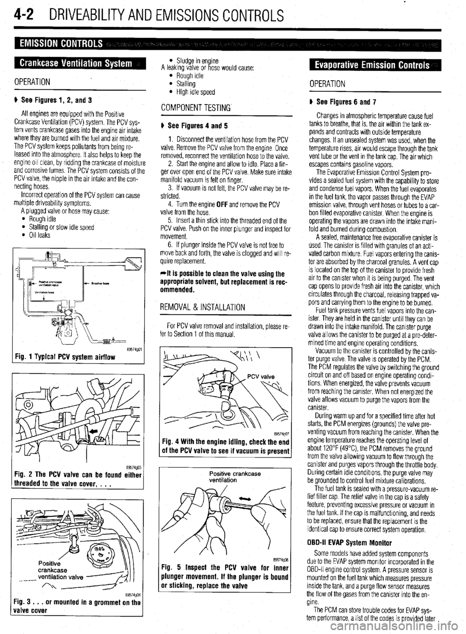
p See Figures 1, 2, and 3
All engines are equipped with the Positive
Crankcase Venhlation (PCV) system. The PCV sys-
tem vents crankcase gases into the engine air intake
where they are burned with the fuel and air mrxture.
The PCV system keeps pollutants from being re-
leased into the atmosphere It also helps to keep the
engine 011 clean, by ridding the crankcase of moisture
and corrosive fumes. The PCV system consists of the
PCV valve, the nipple in the air intake and the con-
necting hoses.
Incorrect operation of the PCV system can cause
multiple driveability symptoms.
A plugged valve or hose may cause’
l Rough Idle l Stalling or slow idle speed l Oil leaks
tT9574goi Fig. 1 Typical PCV system airflow
89574g0r5 Fig. 3 . . .
or mounted in a grommet on the
valve cover
l Sludge in en ine
A leakrng valve or ose would cause: i?
l Rough idle l Stalling l High idle speed
p See Figures 4 and 5
1. Disconnect the ventilation hose from the PCV
valve. Remove the PCV valve from the engine Once
removed, reconnect the ventilation hose to the valve.
2. Start the engine and allow to idle. Place a fin-
ger over open end of the PCV valve. Make sure intake
manifold vacuum is felt on finger.
3. If vacuum is not felt, the PCV valve may be re-
stricted.
4. Turn the engine
OFF and remove the PCV
valve from the hose.
5. Insert a thin stick into the threaded end of the
PCV valve. Push on the inner plunger and inspect for
movement.
6. If plunger inside the PCV valve is not free to
move back and forth, the valve is clogged and WIII re-
quire replacement.
*It is possible to clean the valve using the
appropriate solvent, but replacement is rec-
ommended.
REMOVAL&INSTALLATION
For PCV valve removal and installation, please re-
fer to Section 1 of this manual.
89574QO’ Fig. 4 With the engine idling, check the end
of the PCV valve to see if vacuum is present
Positive crankcase
ventilation
89574go6 Fig. 5 Inspect the PCV valve for inner
plunger movement. If the plunger is bound
or sticking, replace the valve OPERATION
p See Figures 6 and 7
Changes in atmospheric temperature cause fuel
tanks to breathe, that is, the air within the tank ex-
pands and contracts with outside temperature
changes. If an unsealed system was used, when the
temperature rises, air would escape through the tank
vent tube or the vent in the tank cap. The air which
escapes contains gasoline vapors.
The Evaporative Emission Control System pro-
vides a sealed fuel system with the capability to store
and condense fuel vapors. When the fuel evaporates
in the fuel tank, the vapor passes through the EVAP
emission valve, through vent hoses or tubes to a car-
bon filled evaporative canister. When the engine is
operahng the vapors are drawn into the intake mani-
fold and burned during combustion.
A sealed, maintenance free evaporative canister is
used The canister is filled wrth granules of an acti-
vated carbon mixture. Fuel vapors entering the canis-
ter are absorbed by the charcoal granules. A vent cap
is located on the top of the canister to provide fresh
air to the canister when it is being purged. The vent
cap opens to provide fresh air into the canister, which
circulates through the charcoal, releasing trapped va-
pors and carrying them to the engine to be burned.
Fuel tank pressure vents fuel vapors into the can-
ister. They are held in the canister until they can be
drawn into the intake manifold. The canister purge
valve allows the canister to be purged at a pre-deter-
mined time and engine operating conditions.
Vacuum to the canister is controlled by the canis-
ter purge valve. The valve IS operated by the PCM.
The PCM regulates the valve by switching the ground
circuit on and off based on engine operating condi-
tions When energized, the valve prevents vacuum
from reaching the canister. When not energized the
valve allows vacuum to purge the vapors from the
canister.
During warm up and for a specified time after hot
starts, the PCM energizes (grounds) the valve pre-
venting vacuum from reaching the canrster. When the
engine temperature reaches the operating level of
about 120°F (49°C) the PCM removes the ground
from the valve allowing vacuum to flow through the
canister and purges vapors through the throttle body.
During certain Idle conditions, the purge valve may
be grounded to control fuel mixture calibrations.
The fuel tank is sealed with a pressure-vacuum re-
lief filler cap. The relief valve in the cap is a safety
feature, preventing excessive pressure or vacuum in
the fuel tank. If the cap is malfunctioning, and needs
to be replaced, ensure that the replacement is the
identical cap to ensure correct system operation,
OBD-II EVAP System Monitor
Some models have added system components
due to the EVAP system monitor incorporated in the
OBD-II engrne control system. A pressure sensor is
mounted on the fuel tank which measures pressure
inside the tank, and a purge flow sensor measures
the flow of the gases from the canister into the en-
gine.
The PCM can store trouble codes for EVAP sys-
tem performance, a list of the codes is provided later
Page 155 of 408
4112 DRIVEABILITYAND EMISSIONS CONTROLS
.
REMOVAL&INSTALLATION
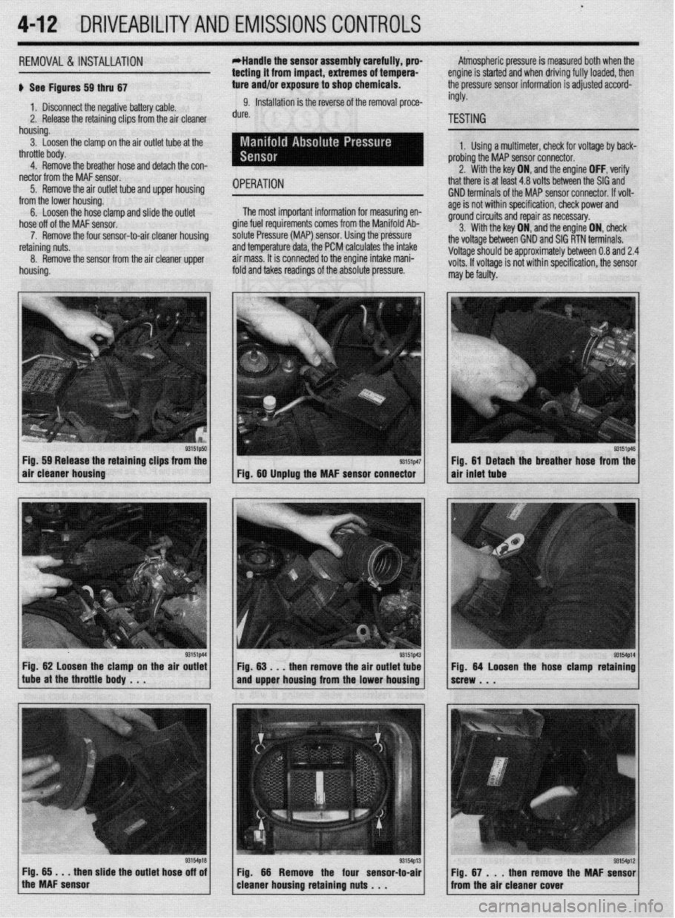
+ See Figures 59 thru 67
1, Disconnect the negative battery cable.
2. Release the retaining clips from the air cleaner
housing.
3. Loosen the clamp on the air outlet tube at the
throttle body.
4. Remove the breather hose and detach the con-
nector from the MAF sensor.
5. Remove the air outlet tube and upper housing
from the lower housing.
6. Loosen the hose clamp and slide the outlet
hose off of the MAF sensor.
7. Remove the four sensor-to-air cleaner housing
retaining nuts.
8. Remove the sensor from the air cleaner upper
housing. Atmospheric pressure is measured both when the
engine is started and when driving fully loaded, then
the oressure sensor information is adiusted accord- *Handle the sensor assembly carefully, pro-
tecting it from impact, extremes of tempera-
ture and/or exposure to shop chemicals.
9. Installation is the reverse of the removal proce-
dure.
OPERATION
The most important information for measuring en-
gine fuel requirements comes from the Manifold Ab-
solute Pressure (MAP) sensor. Using the pressure
and temperature data, the PCM calculates the intake
air mass. It is connected to the engine intake mani-
fold and takes readings of the absolute pressure. ingly.
TESTING
1. Using a multimeter, check for voltage by back-
probing the MAP sensor connector.
2. With the key ON, and the engine OFF, verify
that there is at least 4.8 volts between the SIG and
GND terminals of the MAP sensor connector. If volt-
age is not within specification, check power and
ground circuits and repair as necessary.
3. With the key ON, and the engine ON, check
the voltage between GND and SIG RTN terminals.
Voltage should be approximately between 0.8 and 2.4
volts. If voltage is not within specification, the sensor
r nay be faulty.
Fig. 59 Release the retaining clips from the
air cleaner housing
Fig. 62 loosen the clamp on the air outlet
tube at the throttle body . . .
then slide the outlet hose off of Fig. 61 Detach the breather hose from the
air inlet tube
53154p12 Fig. 67 . . . then remove the MAF sensor
from the air cleaner cover
Page 159 of 408
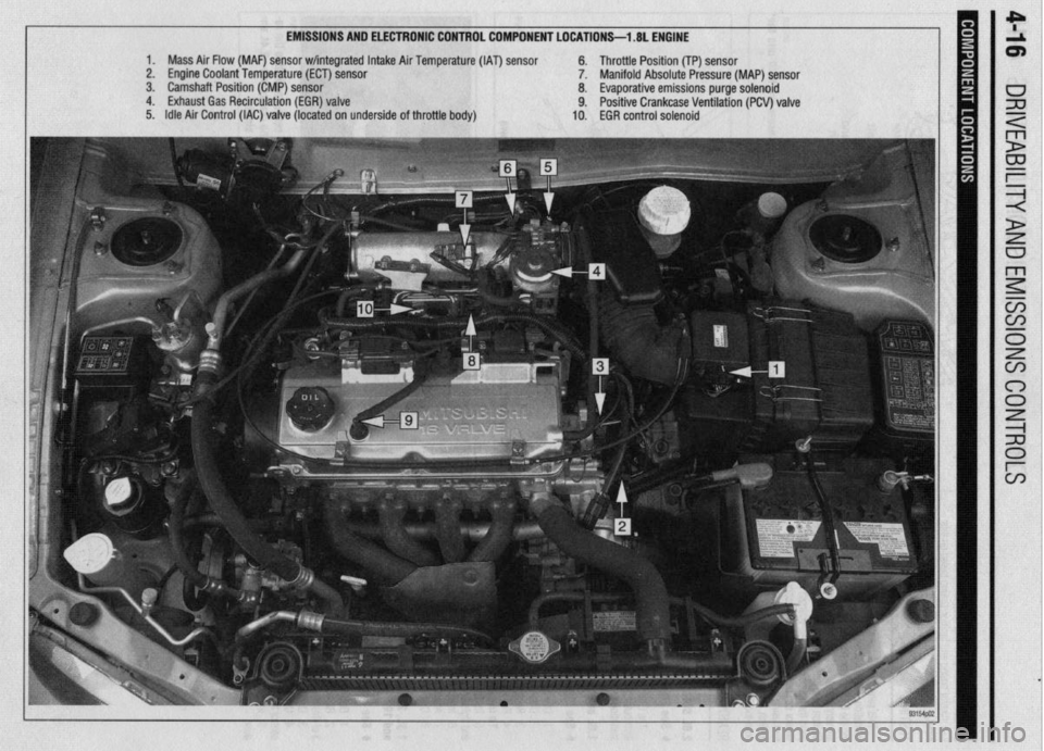
EMISSIONS AND ELECTRONIC CONTROL COMPONENT LOCATIONS-l .8L ENGINE
1. Mass Air Flow (MAF) sensor w/integrated Intake Air Temperature (IAT) sensor 6. Throttle Position (TP) sensor
2. Engine Coolant Temperature (ECT) sensor 7. Manifold Absolute Pressure (MAP) sensor
3. Camshaft Position (CMP) sensor 8. Evaporative emissions purge solenoid
4. Exhaust Gas Recirculation (EGR) valve 9. Positive Crankcase Ventilation (PCV) valve
5. Idle Air Control (IAC) valve (located on underside of throttle body) 10. EGR control solenoid
Page 160 of 408
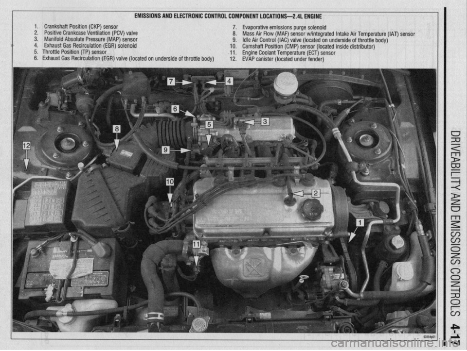
EMISSIONS AND ELECTRONIC CONTROL COMPONENT LOCATIONS-2.4L ENGINE
1. Crankshaft Position (CKP) sensor
7. Evaporative emissions purge solenoid
2. Positive Crankcase Ventilation (PCV) valve
8. Mass Air Flow (MAF) sensor w/integrated Intake Air Temperature (IAT) sensor
3. Manifold Absolute Pressure (MAP) sensor
9. Idle Air Control (IAC) valve (located on underside of throttle body)
4. Exhaust Gas Recirculation (EGR) solenoid
10. Camshaft Position (CMP) sensor (located inside distributor)
5. Throttle Position (TP) sensor
~11. Engine Coolant Temperature (ECT) sensor
6. Exhaust Gas Recirculation (EGR) valve (located on underside of throttle body)
12. EVAP canister (located under fender)