1900 MITSUBISHI DIAMANTE transmission oil
[x] Cancel search: transmission oilPage 35 of 408
.
l-36 GENERALINFORMATIONAND MAINTENANCE
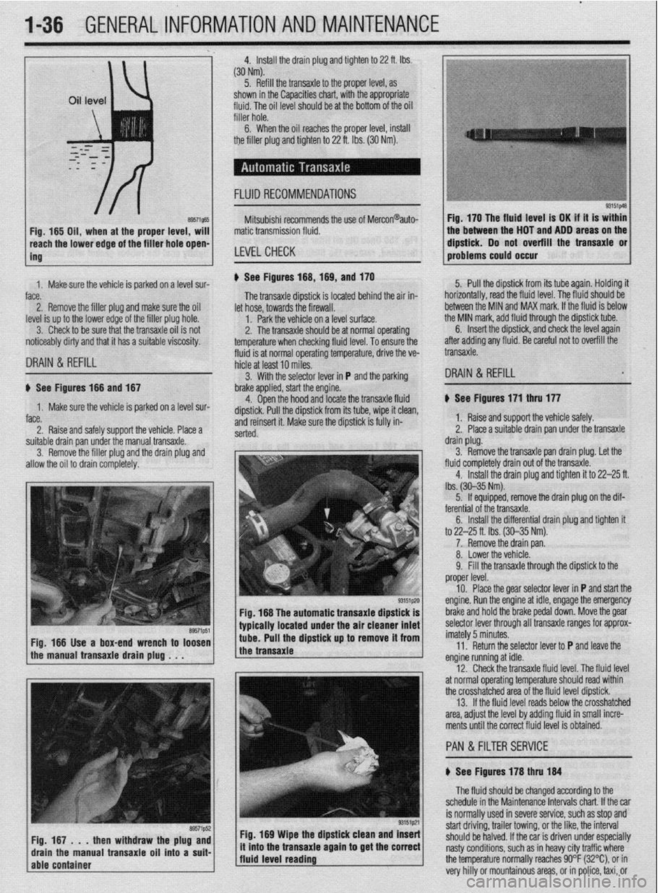
Install the drain plug and tighten to 22 ft. Ibs.
(304Nm)
5. Refill the transaxle to the proper level, as
shown in the Capacities chart, with the appropriate
fluid. The oil level should be at the bottom of the oil
filler hole. I
6. When the oil reaches the orooer level, install
the filler plug and tighten to 22 ft. Ibs. (30 Nm).
FLUID RECOMMENDATIONS
8957i565 Fig, 165 Oil, when at the proper level, will
reach the lower edge of tC=+ frfr*r u*rn -non-
ing Mitsubishi recommends the use of Mercon@auto-
matic transmission fluid.
LEVELCHECK
Fig. 170 The fluid level is OK if it is within
the between the HOT and ADD areas on the
&&i& Do not overfill the transaxle or
-.*".."... -- .*"- problems could o ccur
1. Makesure the vehicle is oarked on a level sur-
face.
2. Remove the filler plug and make sure the oil
level is up to the lower edge of the filler plug hole.
3. Check to be sure that the transaxle oil is not
noticeably dirty and that it has a suitable viscosity. u See Figures 168,169, and 170
fluid is at normal operating temperature, drive the ve- The transaxle dipstick is located behind the air in-
hicle at least 10 miles. let hose, towards the firewall.
1. Park the vehicle on a level surface.
2. The transaxle should be at normal operating
temperature when checking fluid level. To ensure the 5. Pull the dipstick from its tube again. Holding it
horizontally, road the fluid level. The fkrid should be
between the MIN and MAX mark. If the fluid is below
the MIN mark, add fluid through the dipstick tube.
DRAIN & REFILL
6. Insert the dipstick, and check the level again
after adding any fluid. Be careful not to overfill the
transaxle.
3. With the selector lever in P and the parking
DRAIN & REFILL u See Figures 166 and 167
1. Make sure the vehicle is parked on a level sur-
face.
2. Raise and safely support the vehicle. Place a brake applied, start the engine.
4. Open the hood and locate the transaxle fluid
dipstick. Pull the dipstick from its tube, wipe it clean,
and reinsert it. Make sure the dipstick is fully in-
serted.
suitable drain pan under the manual transaxle.
3. Remove the filler plug and the drain plug and
allow the oil to drain completely.
Fig. 166 The automatic transaxle dipstick is
typically located under the air cleaner inlet
Fig. 166 Use a box-end wrench to loosen
the manual transaxle drain plug . . . tube. Pull the dipstick up to remove it from
the transaxle
Fig. 169 Wipe the dipstick clean and Insert
/fluid level reading ., it mto the transaxle agam to get the correct
j The fluid should be changed according to the
schedule in the Maintenance Intervals chart. If the car
is normally used in severe service, such as stop and
start driving, trailer towing, or the like, the interval
should be halved. If the car is driven under especially
nasty conditions, such as in heavy city traffic where
the temperature normally reaches 90°F (32%), or in
very hilly or mountainous areas, or in police, taxi, or b See Figures 171 thru 177
1. Raise and support the vehicle safely.
2. Place a suitable drain pan under the transaxle
drain plug.
3. Remove the transaxle pan drain plug. Let the
fluid completely drain out of the transaxle.
4. Install the drain plug and tighten it to 22-25 ft.
lbs. (30-35 Nm).
5. If equipped, remove the drain plug on the dif-
ferential of the transaxle.
6. Install the differential drain plug and tighten ft
to 22-25 ft. Ibs. (30-35 Nm).
7. Remove the drain pan.
8. Lower the vehicle.
9. Fill the transaxle through the dipstick to the
proper level.
10. Place the gear selector lever in P and start the
engine. Run the engine at idle, engage the emergency
brake and hold the brake pedal down. Move the gear
selector lever through all transaxle ranges for approx-
imately 5 minutes.
11. Return the selector lever to P and leave the
engine running at idle.
12. Check the transaxle fluid level. The fluid level
at normal operating temperature should read within
the crosshatched area of the fluid level dipstick.
13. If the fluid level reads below the crosshatched
area, adjust the level by adding fluid in small incre-
ments until the correct fluid level is obtained.
PAN &FILTER SERVICE
b See Figures 178 thru 184
Page 41 of 408
1-42 GENERAL~INFORMATION AND MAINTENANCE
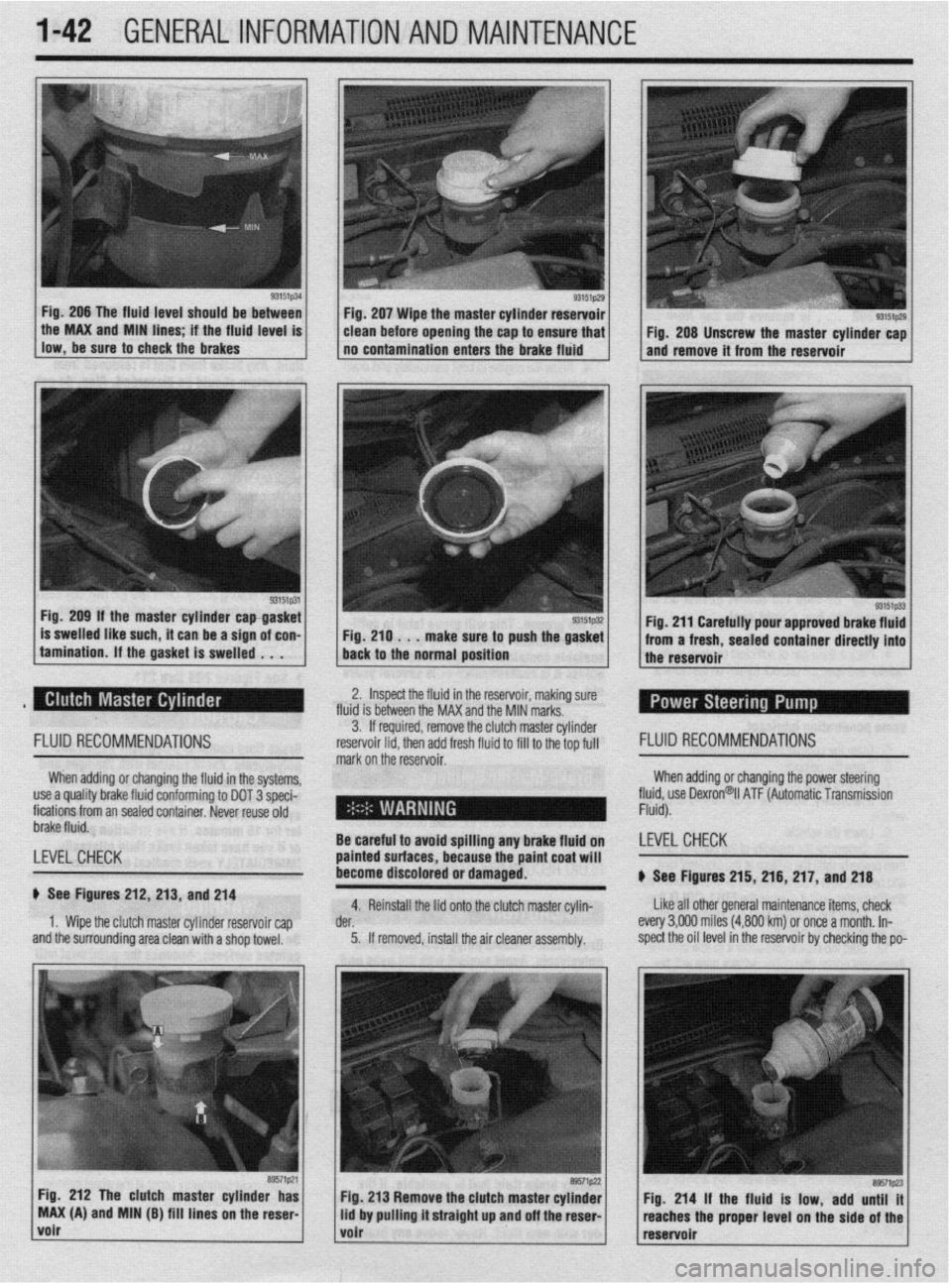
Fig. 206 The fluid level should be between
llow,be*“retoch~ckiebrake~ . the MAX and MIN hnes if the fhud level IS
93151p31 Fig. 209 If the master cylinder capgasket
is swelled like such, it can be a sign of con-
tamination. If the gasket is swelled . . . Fig. 207 Wipe the master cylinder reservoir
clean before opening the cap to ensure that
no contamination enters the brake fluid
Fig. 210 . . .
make sure to push the gasket
back to the normal position
93151p29 I Fig. 208 Unscrew the master cylinder cap
and remove it from the reservoir
Fig. 211 Carefully pour approved brake fluid
from a fresh, sealed container directly into
the reservoir
2. Inspect the fluid in the reservoir, making sure
fluid is between the MAX and the MIN marks.
FLUID RECOMMENDATIONS
When adding or changing the fluid in the systems,
use a quality brake fluid conforming to DOT 3 speci-
fications from an sealed container. Never reuse old
brake fluid.
LEVEL CHECK
b See Figures 212, 213, and 214
1. Wipe the clutch master cylinder reservoir cap
and the surrounding area clean with a shop towel. 3. If required, remove the clut ch master cylinder
reservoir lid. then add fresh fluid I FLUID RECOMMENDATIONS
mark on the’reservoir. to fill to the top full
When adding or changing the power steering
fll$,“” Dexron@il ATF (Automatic Transmission
-
- .
Be careful to avoid sf Billing any brake fluid on LEVELCHECK
painted surfaces, bet
:ause the paint coat will
become discolored or damaged.
b See Figures 215, 216, 217, and 218
4. Reinstall the lid onto the clutch master cylin- Like all other general maintenance items, check
der. every 3,OOfl miles (4,800 km) or once a month. In-
5. If removed, install the air cleaner assembly. spect the oil level in the reservoir by checking the po-
Fig. 212 The clutch master cylinder has
MAX (A) and MIN (B) fill lines on the reser
volr
Page 58 of 408
ENGINE ELECTRICAL 2-11
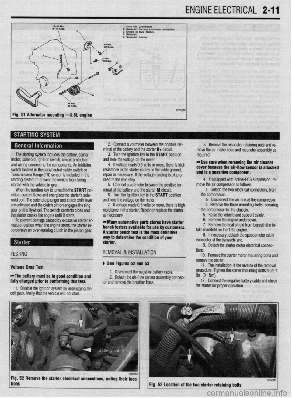
l.unVeMlil(GSflWtWJ
2.Gwwator harness con- connectk,,,
3. Engme OS, level d,pst,&
4 Generator
Fig. 51 Alternator mounting -3.51 engine
The starting system includes the battery, starter
motor, solenoid, ignition switch, circuit protection
and wiring connecting the components. An inhibitor
switch located in the park/neutral safety switch or
Transmission Range (TR) sensor is included in the
starting system to prevent the vehicle from being
started with the vehicle in gear.
When the ignition key is turned to the START po-
sition, current flows and energizes the starters sole-
noid coil. The solenoid plunger and clutch shift lever
are activated and the clutch pinion engages the ring
gear on the flywheel. The switch contacts close and
the starter cranks the engine until it starts.
To prevent damage caused by excessive starter ar-
mature rotation when the engine starts, the starter in-
corporates an over-running clutch in the pinion gear. 2. Connect a voltmeter between the positive ter-
minal of the battery and the starter B+ circuit.
3. Turn the ignition key to the START position
and note the voltage on the meter.
4. If voltage reads 0.5 volts or more, there is high
resistance in the starter cables or the cable ground,
repair as necessary. If the voltage reading is ok pro-
teed to the next step.
5. Connect a voltmeter between the positive ter-
minal of the battery and the starter M circuit,
6. Turn the ignition key to the START position
and note the voltage on the meter.
7. If voltage reads 0.5 volts or more, there is high
resistance in the starter. Repair or replace the starter
as necessary.
*Many automotive parts stores have starter
bench testers available for use by customers.
A starter bench test is the most definitive
way to determine the condition of your
starter. 3. Remove the resonator retaining nuts and re-
move the air intake hose and resonator assembly as
required.
rllse care when removing the air cleaner
cover because the air-flow sensor is attached
and is a sensitive component.
4. If equipped with Active-ECS suspension, re-
move the air compressor as follows:
a. Detach the two electrical connectors, from
the compressor.
b. Disconnect the air line at the compressor.
c. Remove the three mounting bolts, securing
the compressor to the chassis.
5. Raise the vehicle and support safely.
6. Remove the engine undercover.
7. Remove the heat shield from beneath the in-
take manifold on the 1.5L engine.
8. If necessary, detach the speedometer cable
connector at the transaxle end.
9. Detach the starter motor electrical connac-
TESTING
Voltage Drop Test
*The battery must be in good condition and
fully charged prior to performing this test. REMOVAL&INSTALLATION
# See Figures 52 and 53
1. Disconnect the negative battery cable.
2. Detach the air-flow sensor assembly connec-
tor and remove the breather hose.
1. Disable the ignition system by unplugging the
coil pack. Verify that the vehicle will not start. tions.
10. Remove the starter motor mounting bolts and
remove the starter.
11. The installation is the reverse of the removal
procedure. Tighten the starter mounting bolts to 22 ft.
Ibs. (31 Nm).
12. Connect the negative battery cable and check
the starter for proper operation.
9315zp19 Fig. 53 Location of the two starter retaining bolts
Page 126 of 408
I)
ENGINEANDENGINEOVERHAUL 3-65
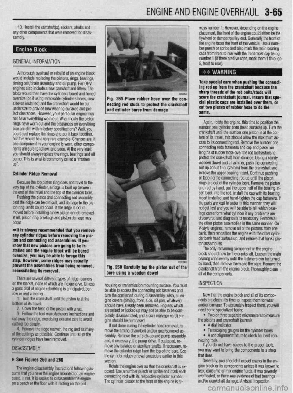
10. Install the camshaft(s), rockers, shafts and
any other components that were removed for disas-
sembly.
GENERAL INFORMATION ways number 1. However, depending on the engine
placement, the front of the engine could either be the
flywheel or damper/pulley end. Generally the front of
the engine faces the front of the vehicle. Use a num-
ber punch or scribe and also mark the main bearing
caps from front to rear with the front most cap being
number 1 (if there are five caps, mark them 1 through
5, front to rear).
A thorough overhaul or rebuild of an engine block
would include replacing the pistons, rings, bearings,
timing belt/chain assembly and oil pump. For OHV
engines also include a new camshaft and lifters. The
block would then have the cylinders bored and honed
oversize (or if using removable cylinder sleeves, new
sleeves installed) and the crankshaft would be cut
undersize to provide new wearing surfaces and per-
feet clearances. However, your particular engine may Take special care when pushing the connect-
ing rod up from the crankshaft because the
sharp threads of the rod bolts/studs will
score the crankshaft journal. Insure that spe-
cial plastic caps are installed over them, or
cut two pieces of rubber hose to do the
same.
Again, rotate the engine, this time to position the
number one cylinder bore (head surface) up. Turn the
crankshaft until the number one piston is at the bot-
tom of its travel, this should allow the maximum ac-
cess to its connecting rod. Remove the number one
connecting rods fasteners and cap and place two
lengths of rubber hose over the rod bolts/studs to
protect the crankshaft from damage. Using a sturdy
wooden dowel and a hammer, push the connecting
rod up about 1 in. (25mm) from the crankshaft and
remove the upper bearing insert. Continue pushing
or tapping the connecting rod up until the piston
rings are out of the cylinder bore. Remove the piston
and rod by hand, put the upper half of the bearing in-
sert back into the rod, install the cap with its bearing
insert installed, and hand-tighten the cap fasteners. If
the parts are kept in order in this manner, they will
not get lost and you will be able to tell which bear-
ings came form what cylinder if any problems are
discovered and diagnosis is necessary. Remove all
the other piston assemblies in the same manner. On
V-style engines, remove all of the pistons from one
bank, then reposition the engine with the other cylin-
der bank head surface up, and remove that banks nis-
prevent the assemblies from being removed,
necessitating its removal. Fig. 260 Carefully tap the piston out of the
bore using a wooden dowel
There are several different types of ridge reamers
on the market, none of which are inexpensive, Unless
.3 “me.+ ,-ins, rdnnn;nn mh~lil.-linn ;I nn+:n:nnL.* l.^W
a ylwx “Gal “I cllylllc Ir;““ll”llly 13 dllLILlpxC”, ““I- row or rent a reamer.
1. Turn the crankshaft until the piston is at the
bottom of its travel.
2. Cover the head of the piston with a rag.
3. Follow the tool manufacturers instructions and housing or transmission mounting surface. You must
1 as many
II of the
~1SA~E~BLY
b See Figures 259 and 260
The engine disassembly instructions following as-
sume that you have the engine mounted on an engine
stand. If not, it is easiest to disassemble the engine
on a bench or the floor with it resting on the bell be able to access the connecting rod fasteners and
turn the crankshaft during disassembly. Also, all en-
gine covers (timing, front, side, oil pan, whatever)
should
are sei2
nletelv have already been removed. Engines which
,ed or locked up may not be able to be com-
r’-‘-‘, disassembled, and a core (salvage yard) en-
gine sh ould be purchased.
If no
t done during the cylinder head removal, re-
move the timing chain/belt and/or gear/sprocket as-
sembly. Remove the oil pick-up and pump assembly
and, if necessary, the pump drive. If equipped, re-
move any balance or auxiliary shafts. If necessary, re-
move the cylinder ridge from the top of the bore. See
the cylinder ridge removal procedure earlier in this
section.
Rotate the engine over so that the crankshaft is ex-
posed. Use a number punch or scribe and mark each
connecting rod with its respective cylinder number.
The cylinder closest to the front of the engine is al- cut away the ridge, exercising extreme care to avoid
~ ioo deepfy.
4. Remove the ridge reamer, the rag and
armings as possible. Continue until a
biter ridges have been removed. ton assemblies.
The only remaining component in the engine
block should now be the crankshaft. Loosen the main
bearing caps evenly until the fasteners can be turned
by hand, then remove them and the caps. Remove the
crankshaft from the engine block. Thoroughly clean
all of the components.
INSPECTION
Now that the engine block and all of its compo-
nents are clean, it’s time to inspect them for wear
and/or damage. To accurately inspect them, you will
need some specialized tools:
l Two or three separate micrometers to measure
the prstons and crankshaft journals
l A dial indicator l Telescoping gauges for the cylinder bores l A rod alignment fixture to check for bent con-
netting rods
If you do not have access to the proper tools,
you may want to bring the components to a shop
that does.
Generally, you shouldn’t expect cracks in the en-
gine block or its components unless it was known to
leak, consume or mix engine fluids, it was severely
overheated, or there was evidence of bad bearings
and/or crankshaft damage. A visual inspection
Page 170 of 408
DRIVEABILITYAND EMISSIONS CONTROLS 4-27
WITHOUTASCANTOOL
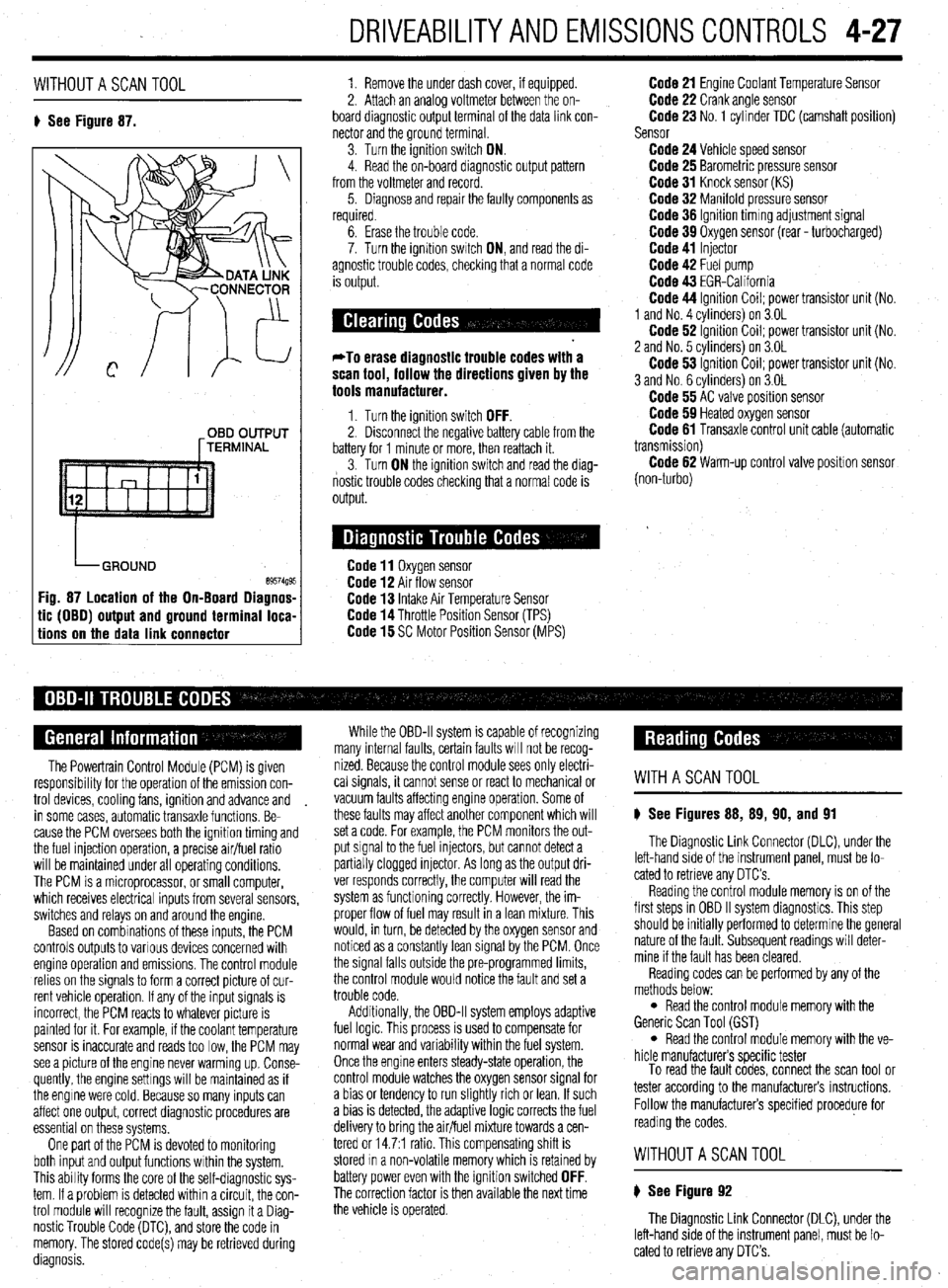
8 See Figure 87. 1. Remove the under dash cover, if equipped.
2. Attach an analoa voltmeter between the on-
board diagnostic outpit terminal of the data link con-
nector and the ground terminal
3. Turn the ignition switch ON.
4. Read the on-board diagnostic output pattern
from the voltmeter and record.
5. Diagnose and repair the faulty components as
required.
OBD OUTPUT
[TERMINAL
tic (OBO) output and ground terminal loca-
tions on the data link connector
6. Erase the trouble code.
7. Turn the ignition swatch ON, and read the di-
agnostic trouble codes, checking that a normal code
is output.
*To erase diagnostic trouble codes with a
scan tool, follow the directions given by the
tools manufacturer.
1. Turn the ignition switch OFF. 2. Disconnect the negative battery cable from the
battery for 1 minute or more, then reattach it.
3. Turn ON the ignition switch and read the diag-
nostic trouble codes checking that a normal code is
output.
Code 11 Oxygen sensor Code 12 Air flow sensor Code 13 Intake Air Temperature Sensor Code 14 Throttle Position Sensor (TPS) Code 15 SC Motor Position Sensor (MPS)
Code 21 Engine Coolant Temperature Sensor Code 22 Crank angle sensor Code 23 No. 1 cylinder TDC (camshaft position)
Sensor
Code 24 Vehicle speed sensor Code 25 Barometric pressure sensor Code 31 Knock sensor (KS) Code 32 Manifold pressure sensor Code 36 Ignition timmg adjustment signal Code 39 Oxygen sensor (rear - turbocharged) Code 41 Injector Code 42 Fuel pump Code 43 EGR-California Code 44 Ignition Coil; power transistor unit (No.
1 and No. 4 cvlinders) on 3.OL
Code 62 ignition Coil; power transistor unit (No.
2 and No. 5 cvlinders) on 3.OL
Code 53 ignition Coil; power transistor unit (No.
3 and No. 6 cylinders) on 3.OL
Code 55 AC valve position sensor Code 59 Heated oxygen sensor Code 61 Transaxle control unit cable (automatic
transmission)
Code 62 Warm-up control valve position sensor
(non-turbo)
The Powertrain Control Module (PCM) is given
responsibrlity for the operation of the emission con-
trol devices, cooling fans, ignition and advance and
in some cases, automatic transaxle functions. Be-
cause the PCM oversees both the ignition timing and
the fuel injection operation, a precise air/fuel ratio
will be maintained under all operating conditions,
The PCM is a microprocessor, or small computer,
which receives electrical inputs from several sensors,
switches and relays on and around the engine.
Based on combinations of these inputs, the PCM
controls outputs to various devices concerned with
engine operation and emissions. The control module
relies on the signals to form a correct picture of cur-
rent vehicle operation. If any of the input signals is
incorrect, the PCM reacts to whatever picture is
painted for it. For example, if the coolant temperature
sensor is inaccurate and reads too low, the PCM may
see a picture of the engine never warming up. Conse-
quently, the engine settings will be maintained as if
the engine were cold. Because so many inputs can
affect one output, correct diagnostic procedures are
essential on these systems,
One part of the PCM is devoted to monitoring
both input and output functions within the system.
This ability forms the core of the self-diagnostic sys-
tem. If a problem is detected within a circuit, the con-
trol module will recognize the fault, assign it a Diag-
nostic Trouble Code (DTC), and store the code in
memory. The stored code(s) may be retrieved during
diagnosis. While the OBD-II system is capable of recognizing
many internal faults, certain faults WIII not be recog-
nized. Because the control module sees only electri-
cal signals, it cannot sense or react to mechanical or
vacuum faults affecting engine operation. Some of
these faults may affect another component which will
set a code. For example, the PCM monitors the out-
put signal to the fuel injectors, but cannot detect a
partially clogged injector. As long as the output dri-
ver responds correctly, the computer will read the
system as functioning correctly. However, the im-
proper flow of fuel may result in a lean mixture. This
would, in turn, be detected by the oxygen sensor and
noticed as a constantly lean signal by the PCM. Once
the signal falls outside the pre-programmed limits,
the control module would notice the fault and set a
trouble code.
Additionally, the OBD-II system employs adaptive
fuel logic. This process is used to compensate for
normal wear and variability within the fuel system.
Once the engine enters steady-state operation, the
control module watches the oxygen sensor signal for
a bias or tendency to run slightly rich or lean. If such
a bias is detected, the adaptive logic corrects the fuel
delivery to bring the air/fuel mixture towards a cen-
tered or 14.7:1 ratio. This compensating shift is
stored In a non-volatile memory which is retained by
battery power even with the ignition switched
OFF. The correction factor is then available the next time
the vehicle is operated.
WITHASCANTOOL
8 See Figures 88, 89, 90, and 91
The Diagnostic Link Connector (DLC), under the
left-hand side of the instrument panel, must be lo-
cated to retrieve any OTC’s
Reading the control module memory is on of the
first steps in OBD II system diagnostics. This step
should be initially performed to determine the general
nature of the fault. Subsequent readings will deter-
mine if the fault has been cleared.
Reading codes can be performed by any of the
methods below:
l Read the control module memory with the
Generic Scan Tool (GST)
l Read the control module memory with the ve-
hicle manufacturers specific tester
To read the fault codes, connect the scan tool or
tester according to the manufacturers instructions.
Follow the manufacturers specified procedure for
reading the codes.
WITHOUTASCANTOOL
8 See Figure 92
The Diagnostic Link Connector (DLC), under the
left-hand side of the instrument panel, must be lo-
cated to retrieve any DTC’s.
Page 172 of 408
DRIVEABILITYAND EMISSIONS CONTROLS 4-29
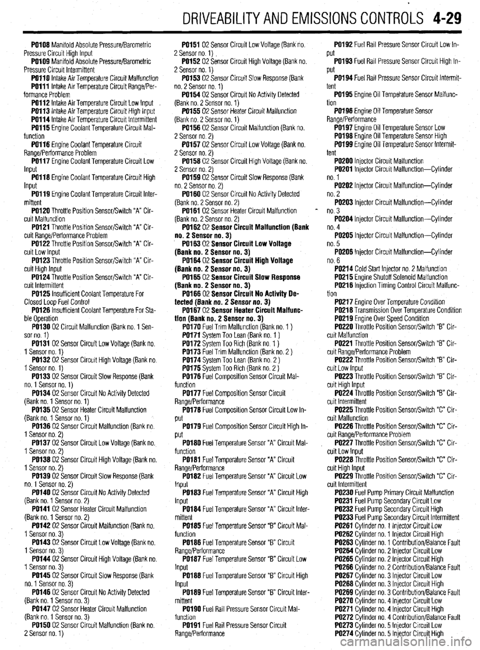
PO108 Manifold Absolute Pressure/Barometric
Pressure Circuit High Input
PO109 Manifold Absolute Pressure/Barometric
Pressure Circuit Intermittent
PO110 intake Air Temperature Circuit Malfunction
PO111 Intake Air Temperature Circuit Range/Per-
formance Problem
PO112 Intake Air Temperature Circuit Low Input
PO113 Intake Air Temoerature Circuit Hiah lnout
PO114 Intake Air Temberature Circuit lnt&miitent
PO115 Engine Coolant Temperature Circuit Mal-
function -
PO116 Engine Coolant Temperature Circuit
Range/Performance Problem
PO117 Engine Coolant Temperature Circuit Low
Input
PO118 Engine Coolant Temperature Circuit High
Input
PO119 Engine Coolant Temperature Circuit Inter-
mittent
PO120 Throttle Position Sensor/Switch “A” Cir-
cuit Malfunction
PO121 Throttle Position Sensor/Switch “A” Cir-
cuit Range/Performance Problem
PO122 Throttle Position Sensor/Switch “A” Cir-
cuit Low Input
PO123 Throttle Position Sensor/Switch “A” Cir-
cuit High Input
PO124 Throttle Position Sensor/Switch “A” Cir-
cuit Intermittent
PO125 Insufficient Coolant Temperature For
Closed Loop Fuel Control
PO126 Insufficient Coolant Temperature For Sta-
ble Operation
PO130 02 Circuit Malfunction (Bank no. 1 Sen-
sor no. 1)
PO131 02 Sensor Circuit Low Voltage (Bank no.
1 Sensor no. 1)
PO132 02 Sensor Circuit High Voltage (Bank no.
1 Sensor no. 1)
PO133 02 Sensor Circuit Slow Response (Bank
no. 1 Sensor no. 1)
PO134 02 Sensor Circuit No Activity Detected
(Bank no. 1 Sensor no. 1)
PO135 02 Sensor Heater Circuit Malfunction
(Bank no. 1 Sensor no. 1)
PO136 02 Sensor Circuit Malfunction (Bank no.
1 Sensor no. 2)
PO137 02 Sensor Circuit Low Voltage (Bank no.
1 Sensor no. 2)
PO138 02 Sensor Circuit High Voltage (Bank no.
1 Sensor no. 2)
PO139 02 Sensor Circuit Slow Response (Bank
no. 1 Sensor no. 2)
PO140 02 Sensor Circuit No Activity Detected
(Bank no. 1 Sensor no. 2)
PO141 02 Sensor Heater Circuit Malfunction
(Bank no. 1 Sensor no. 2)
PO142 02 Sensor Circuit Malfunction (Bank no.
1 Sensor no. 3)
PO143 02 Sensor Circuit Low Voltage (Bank no.
1 Sensor no. 3)
PO144 02 Sensor Circuit High Voltage (Bank no.
1 Sensor no. 3)
PO145 02 Sensor Circuit Slow Response (Bank
no. 1 Sensor no. 3)
PO146 02 Sensor Circuit No Activity Detected
(Bank no. 1 Sensor no. 3)
PO147 02 Sensor Heater Circuit Malfunction
(Bank no. 1 Sensor no. 3)
PO150 02 Sensor Circuit Malfunction (Bank no.
2 Sensor no. 1) PO151 02 Sensor Circuit Low Voltage (Bank no.
2 Sensor no. 1)
PO152 02 Sensor Circuit High Voltage (Bank no.
2 Sensor no. 1)
PO153 02 Sensor Circuit Slow Response (Bank
no. 2 Sensor no. 1)
PO154 02 Sensor Circuit No Activity Detected
(Bank no. 2 Sensor no. 1)
PO155 02 Sensor Heater Circuit Malfunction
(Bank no. 2 Sensor no. 1)
PO156 02 Sensor Circuit Malfunction (Bank no.
2 Sensor no. 2)
PO157 02 Sensor Circuit Low Voltage (Bank no.
2 Sensor no. 2)
PO158 02 Sensor Circuit High Voltage (Bank no.
2 Sensor no. 2)
PO159 02 Sensor Circuit Slow Response (Bank
no. 2 Sensor no. 2)
PO160 02 Sensor Circuit No Activity Detected
(Bank no. 2 Sensor no. 2)
PO161 02 Sensor Heater Circuit Malfunction
(Bank no. 2 Sensor no. 2)
PO162 02 Sensor CircuitMalfunction(8ank
no.2 Sensorno.3)
PO16302 Sensor Circuit Low Voltage
(Bankno. Sensorno.3)
PO16402 Sensor Circuit HighVoltage
(Bankno. Sensorno.3)
PO16502 Sensor Circuit Slow Response
(Bankno. Sensorno.3)
PO166 02 Sensor Circuit No Activity De-
tected(Bankno.2 Sensorno.3)
PO16702 SensorHeaterCircuitMalfunc-
tion(Bank no.2 Sensorno.3)
PO170 Fuel Trim Malfunction (Bank no. 1 )
PO171 System Too Lean (Bank no. 1 )
PO172 Svstem Too Rich (Bank no 1 )
PO173 F;el Trim Malfundtion (Bank io. 2 )
PO174 System Too Lean (Bank no 2 )
PO175 System Too Rich (Bank no. 2 )
PO176 Fuel Composition Sensor Circuit Mal-
function
PO177 Fuel Composition Sensor Circuit
Range/Performance
PO178 Fuel Composition Sensor Circuit Low In-
put
PO179 Fuel Composition Sensor Circuit High In-
put
PO180 Fuel Temperature Sensor “A” Circuit Mal-
function
PO181 Fuel Temperature Sensor “A” Circuit
Range/Performance
PO182 Fuel Temperature Sensor “A” Circuit Low
Input
PO183 Fuel Temperature Sensor “A” Circuit High
Input
PO184 Fuel Temperature Sensor “A” Circuit Inter-
mittent
PO185 Fuel Temperature Sensor “B” Circuit Mal-
function
PO186 Fuel Temperature Sensor “B” Circuit
Range/Performance
PO187 Fuel Temperature Sensor “B” Circuit Low
Input
PO188 Fuel Temperature Sensor “B” Circuit High
Input
PO189 Fuel Temperature Sensor “B” Circuit Inter-
mittent
PO190 Fuel Rail Pressure Sensor Circuit Mal-
funchon
PO191 Fuel Rail Pressure Sensor Circuit
Range/Performance PO192 Fuel Rail Pressure Sensor Circuit Low In-
put
PO193 Fuel Rail Pressure Sensor Circuit High In-
put
PO194 Fuel Rail Pressure Sensor Circuit Intermit-
tent
PO195 Engine Oil Tempetature Sensor Malfunc-
tion
PO198 Engine Oil Temperature Sensor
Range/Performance
PO197 Engine Oil Temperature Sensor Low
PO198 Engine Oil Temperature Sensor High
W199 Engine Oil Temperature Sensor Intermit-
tent
PO200 Injector Circuit Malfunction
PO201 Injector Circuit Malfunction-Cylinder
no. 1
PO202 Injector Circuit Malfunction-Cylinder
no. 2
PO203 Injector Circuit Malfunction-Cylinder
no. 3
PO204 Injector Circuit Malfunction-Cylinder
no. 4
PO205 Injector Circuit Malfunction-Cylinder
no. 5
PO206 Injector Circuit Malfunction-Cylinder
no. 6
PO214 Cold Start Injector no. 2 Malfunction
PO215 Engine Shutoff Solenoid Malfunction
PO218 Injection Timing Control Circuit Malfunc-
tion
PO217 Engine Over Temperature Condition
PO218 Transmission Over Temperature Condition
PO219 Engine Over Speed Condition
PO220 Throttle Position Sensor/Switch ‘9” Cir-
cuit Malfunction
PO221 Throttle Position Sensor/Switch “B” Cir-
cuit Range/Performance Problem
PO222 Throttle Position Sensor/Switch “B” Cir-
cuit Low Input
PO223 Throttle Position Sensor/Switch “B” Cir-
cuit High Input
PO224 Throttle Position Sensor/Switch “B” Cir-
cuit Intermittent
PO225 Throttle Position Sensor/Switch “C” Cir-
cuit Malfunction
PO226 Throttle Position Sensor/Switch “C” Cir-
cuit Range/Performance Problem
PO227 Throttle Position Sensor/Switch “c” Cir-
cuit Low Input
PO228 Throttle Position Sensor/Switch “C” Cir-
cuit High Input
PO229 Throttle Position Sensor/Switch “C” Cir-
cuit Intermittent
PO230 Fuel Pump Primary Circuit Malfunction
PO231 Fuel Pump Secondary Circuit Low
PO232 Fuel Pump Secondary Circuit High
PO233 Fuel Pump Secondary Circuit Intermittent
PO261 Cylinder no. 1 Injector Circuit Low
PO262 Cylinder no. 1 Injector Circuit High
PO263 Cylinder no. 1 Contribution/Balance Fault
PO264 Cvlinder no. 2 lniector Circuit Low
PO265 Cylinder no. 2 Injector Circuit High
PO266 Cylinder no. 2 Contribution/Balance Fault
PO267 Cylinder no. 3 Injector Circuit Low
PO268 Cylinder no. 3 Injector Circuit High
PO269 Cylinder no. 3 Contribution/Balance Fault
PO270 Cylinder no. 4 Injector Circuit Low
PO271 Cvlinder no. 4 lniector Circuit Hiah
PO272 Cylinder no. 4 CbntributionlBalaice Fault
PO273 Cylinder no. 5 Injector Circuit Low
PO274 Cylinder no. 5 Injector Circuit High
Page 174 of 408
DRIVEABILITYAND EMISSIONSCONTROL-S 4-31
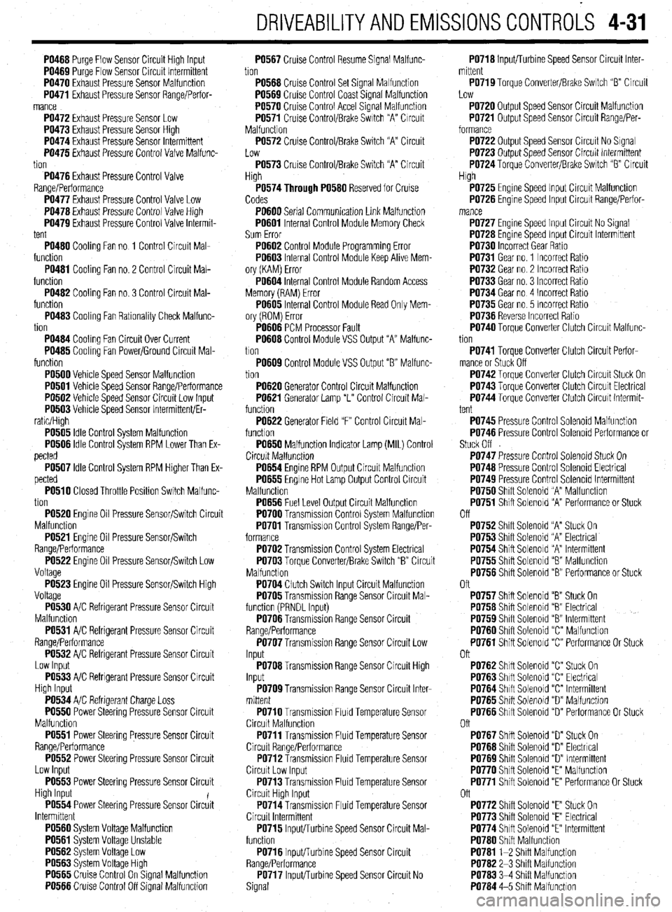
PO466 Purge Flow Sensor Circuit High Input
PO469 Purqe Flow Sensor Circuit Intermittent
PO470 Exhaust Pressure Sensor Malfunction
PO471 Exhaust Pressure Sensor Range/Perfor-
mance
PO472 Exhaust Pressure Sensor Low
PO473 Exhaust Pressure Sensor Hiah
PO474 Exhaust Pressure Sensor lnirmittent
PO475 Exhaust Pressure Control Valve Malfunc-
tion
PO476 Exhaust Pressure Control Valve
Range/Performance
PO477 Exhaust Pressure Control Valve Low
PO476 Exhaust Pressure Control Valve High
PO479 Exhaust Pressure Control Valve Intermit-
tent
PO460 Cooling Fan no 1 Control Circuit Mal-
function
PO461 Cooling Fan no. 2 Control Circuit Mal-
function
PO462 Cooling Fan no. 3 Control Circuit Mal-
function
PO463 Cooling Fan Rationality Check Malfunc-
tion
PO464 Cooling Fan Circuit Over Current
PO465 Cooling Fan Power/Ground Circuit Mal-
function
PO500 Vehicle Speed Sensor Malfunction
PO501 Vehicle Speed Sensor Range/Performance
PO502 Vehicle Speed Sensor Circuit Low Input
PO503 Vehicle Speed Sensor Intermittent/Er-
ratic/High
PO505 Idle Control System Malfunction
PO506 Idle Control System RPM Lower Than Ex-
pected
PO507 Idle Control System RPM Higher Than Ex-
pected
PO510 Closed Throttle Position Switch Malfunc-
tion
PO520 Engine Oil Pressure Sensor/Switch Circuit
Malfunction
PO521 Engine Oil Pressure Sensor/Switch
Range/Performance
PO522 Engine Oil Pressure Sensor/Switch Low
Voltage
PO523 Engine Oil Pressure Sensor/Switch High
Voltage
PO530 A/C Refrigerant Pressure Sensor Circuit
Malfunction
PO531 A/C Refrigerant Pressure Sensor Circuit
Range/Performance
PO532 A/C Refrigerant Pressure Sensor Circuit
Low Input
PO533 A/C Refrigerant Pressure Sensor Circuit
High Input
PO534 A/C Refrigerant Charge Loss
PO550 Power Steering Pressure Sensor Circuit
Malfunction
PO551 Power Steering Pressure Sensor Circuit
Range/Performance
PO552 Power Steering Pressure Sensor Circuit
Low Input
PO553 Power Steering Pressure Sensor Circuit
High Input
PO554 Power Steering Pressure Sensor Circiit
Intermittent
PO560 System Voltage Malfunction
PO561 System Voltage Unstable
PO562 System Voltage Low
PO563 Svstem Voltaoe Hlah
PO565 Ciuise Control On%ignal Malfunction
PO566 Cruise Control Off Signal Malfunction PO567 Cruise Control Resume Signal Malfunc-
tion
PO566 Cruise Control Set Signal Malfunction
PO569 Cruise Control Coast Signal Malfunction
PO570 Cruise Control Accel Signal Malfunction
PO571 Cruise Control/Brake Switch “A” Circuit
Malfunction
PO572 Cruise Control/Brake Switch “A” Circuit
Low
PO573 Cruise Control/Brake Switch “A” Circuit
High
P0574Through PO560 Reserved for Cruise
Codes
PO600 Serial Communication Link Malfunction
PO601 Internal Control Module Memory Check
Sum Error
PO602 Control Module Programming Error
PO603 Internal Control Module Keep Alive Mem-
ory (KAM) Error
PO604 Internal Control Module Random Access
Memory (RAM) Error
PO605 Internal Control Module Read Only Mem-
ory (ROM) Error
PO606 PCM Processor Fault
PO606 Control Module VSS Output “A” Malfunc-
tion
PO609 Control Module VSS Output “6” Malfunc-
tion
PO620 Generator Control Circuit Malfunction
PO621 Generator Lamp “L” Control Circuit Mal-
function
PO622 Generator Field “F” Control Circuit Mal-
function
PO650 Malfunction Indicator Lamp (MIL) Control
Circuit Malfunctron
PO654 Engine RPM Output Circuit Malfunction
PO655 Engine Hot Lamp Output Control Circuit
Malfunction
PO656 Fuel Level Output Circuit Malfunction
PO700 Transmission Control System Malfunction
PO701 Transmission Control System Range/Per-
formance
PO702 Transmission Control System Electrical
PO703 Torque Converter/Brake Switch “B” Circuit
Malfunction
PO704 Clutch Switch Input Circuit Malfunction
PO705 Transmission Range Sensor Circuit Mal-
function (PRNDL Input)
PO706 Transmission Range Sensor Circuit
Range/Performance
PO707 Transmission Range Sensor Circuit Low
Input
PO706 Transmission Range Sensor Circuit High
Input
PO709 Transmission Range Sensor Circuit Inter-
mittent
PO710 Transmission FluId Temperature Sensor
Circuit Malfunction
PO711 Transmission Fluid Temperature Sensor
Circuit Range/Performance
PO712 Transmission Fluid Temperature Sensor
Circuit Low Input
PO713 Transmission Fluid Temperature Sensor
Circuit High Input
PO714 Transmission Fluid Temperature Sensor
Circuit Intermittent
PO715 Input/Turbine Speed Sensor Circuit Mal-
function
PO716 Input/Turbine Speed Sensor Circuit
Range/Performance
PO717 InpWurbine Speed Sensor Circuit No
Signal PO716 Inputflurbine Speed Sensor Circuit Inter-
mittent
PO719 Torque Converter/Brake Switch “B” Circuit
Low
PO720 Output Speed Sensor Circuit Malfunction
PO721 Output Speed Sensor Circuit Range/Per-
formance
PO722 Output Speed Sensor Circuit No Signal
PO723 Output Speed Sensor Circuit Intermittent
PO724 Toraue Converter/Brake Switch “B” Circuit
High
PO725 Engine Speed Input Circuit Malfunction
PO726 Engine Speed Input Circuit Range/Perfor-
PO727 Engine Speed Input Circuit No Signal
PO726 Engine Speed Input Circuit Intermittent
PO730 Incorrect Gear Ratio
PO731 Gear no. 1 Incorrect Ratio
PO732 Gear no. 2 Incorrect Ratio
PO733 Gear no. 3 Incorrect Ratio
PO734 Gear no 4 Incorrect Ratio
PO735 Gear no. 5 Incorrect Ratio
PO736 Reverse Incorrect Ratio
PO740 Torque Converter Clutch Circuit Malfunc-
tion
PO741 Torque Converter Clutch Circuit Perfor-
mance or Stuck Off
PO742 Torque Converter Clutch Circuit Stuck On
PO743 Torque Converter Clutch Circuit Electrical
PO744 Torque Converter Clutch Circuit Intermit-
tent
PO745 Pressure Control Solenoid Malfunction
PO746 Pressure Control Solenoid Performance or
Stuck Off
PO747 Pressure Control Solenoid Stuck On
PO746 Pressure Control Solenoid Electrical
PO749 Pressure Control Solenoid Intermittent
PO750 Shift Solenoid “A” Malfunction
PO751 Shift Solenoid “A” Performance or Stuck
Off
PO752 Shift Solenoid “A” Stuck On
PO753 Shift Solenoid “A” Electrical
PO754 Shift Solenoid “A” Intermittent
PO755 Shift Solenoid “8 Malfunction
PO756 Shift Solenoid “B” Performance or Stuck
Oft
PO757 Shift Solenoid “B” Stuck On
PO756 Shift Solenoid “6” Electrical
PO759 Shift Solenoid “8” Intermittent
PO760 Shift Solenoid “C” Malfunction
PO761 Shift Solenoid “C” Performance Or Stuck
Oft
PO762 Shift Solenoid “C” Stuck On
PO763 Shift Solenoid “C” Electrical
PO764 Shift Solenoid “C” Intermittent
PO765 Shift Solenoid “D” Malfunction
PO766 Shift Solenoid “D” Performance Or Stuck
Oft
PO767 Shift Solenoid “D” Stuck On
PO766 Shift Solenoid “D” Electrical
PO769 Shift Solenoid “D” Intermittent
PO770 Shift Solenoid “E” Malfunction
PO771 Shift Solenoid “E” Performance Or Stuck
Off
PO772 Shift Solenoid “E” Stuck On
PO773 Shift Solenoid “E” Electrical
PO774 Shift Solenoid “E” Intermittent
PO760 Shift Malfunction
PO761 l-2 Shift Malfunction
PO762 2-3 Shift Malfunction
PO763 3-4 Shift Malfunction
PO764 4-5 Shift Malfunction
Page 282 of 408
DRIVETRAIN 7-3
7. Remove the connection for the clutch release
38. Install the battery.
bolt to 54 ft. Ibs. (73 Nm). Install the front engine roll
cylinder and without disconnecting the hydraulic line,
39. If equipped with Active-ECS, connect the air
stopper through-bolt and hand-tighten. Once the full
and secure it aside.
compressor.
weight of the engine is on the mounts, tighten the
8. Disconnect the backup light switch harness
40. Make sure the vehicle is level when refilling
bolt to 42 ft. Ibs. (57 Nm).
and position aside.
the transaxle. Use Hypoid gear oil or equivalent, GL-
30.
Install the triangular stay bracket and tighten
9. Detach the starter electrical connections, if
4 or higher.
the mounting bolts to 65 ft. Ibs. (88 Nm).
necessary, remove the starter motor and position
41. Check the transaxle and transfer case for
31. Connect the clutch release cylinder.
aside.
proper operation. Make sure the reverse lights come
32. Install the halfshafts, using new circlips on
10. Remove the transaxle mount bracket.
on when in reverse.
the axle ends.
11. Remove the upper transaxle mounting bolts.
12.
Raise the vehicle and support safely on jack-
1!I94-Ol? MODELS
stands.
13. Remove the undercover and the front wheels. 1. Disconnect the negative battery cable and When histalling the axleshaft, keep the in-
14.
Remove the cotter pin and disconnect the tie wait at least 90 seconds before performing any work. board joint straight in relation to the axle, so
rod end from the steering knuckle. 2. Remove the air cleaner and intake hoses. not to damage the oil seal lip of the
15. Remove the self-locking nut from the half- 3. Drain the transaxle into a suitable waste con- transaxle, with the serrated part of the half-
ShaftS. tainer. shaft.
16.
Disconnect the lower arm ball joint from the 4. Remove the cotter pins and clips securing the
steering knuckle. select and shift cables and remove the cable ends 33. Connect the tie rod and ball joints to the steer-
17. Remove the halfshafts from the transaxle. from the transaxle. ing knuckle. Tighten the ball joint self-locking nuts to
18. On AWD models, disconnect the front ex- 5. If equipped with Active-ECS, disconnect the 48 ft. Ibs. (65 Nm). Tighten the tie rod end nut to 21 ft.
haust pipe. air compressor. Ibs. (28 Nm) and secure with a new cotter pin.
19.
On AWD ‘models, remove the transfer case by 6. Disconnect the backup light switch harness 34.
Connect the damper fork to the lower control
removing the attaching bolts, moving the transfer and position aside. arm and tighten the through-bolt to 65 ft. Ibs. (88 Nm).
case to the left and lowering the front side. Remove it 7. Disconnect the speedometer electrical con- 35.
Connect the stabilizer link to the damper fork,
from the rear driveshaft. Be careful of the oil seal. Do nectar, from the transaxle assembly. and tighten the self-locking nut to 29 ft. Ibs. (39 Nm).
not allow the driveshaft to hang; once the front is re- 8. Remove the starter motor and position aside. 36. Install the underpan.
moved from the transfer, tie it up. Cover the transfer 9. Using special tool M2203827 or equivalent, 37. Install wheels and lower vehicle.
case openings to keep out dirt. support the engine assembly. 38. Install the transaxle mount bracket to the
20.
Remove the cover from the transaxle bell- 10. Remove the rear roll stopper mounting transaxle, and tighten the mounting nuts to 32 ft. Ibs.
housing. bracket. (43 Nm).
21. On AWD models, remove the crossmember 11. Remove the transaxle mount bracket. 39. install the rear roll stopper mounting bracket.
and the triangular gusset. 12. Remove the upper transaxle mounting bolts. 40.
Remove the engine support. Tighten the
22. Remove the transaxle lower coupling bolt. It 13. Raise and safely support the vehicle. transaxle mount through-bolt to 51 ft. Ibs. (69 Nm)
is just above the halfshaft opening on FWD or trans- 14. Remove the front wheel assemblies. and tighten the front engine roll stopper through-bolt.
fer case opening on AWD. 15. Remove the right hand undercover. 41. Install the upper transaxle mounting bolts
23.
Support the weight of the engine from above 16. Remove the cotter pin and disconnect the tie and tighten to 35 ft. Ibs. (48 Nm).
(chain hoist). Support the transaxle using a transmis- rod end, from the steering knuckle. 42. Install the starter motor.
sion jack and remove the remaining lower mounting 17. Disconnect the stabilizer bar link, from the 43. Attach the backup light switch and the
bolts. damper fork. speedometer connector.
24. On turbocharged vehicle, be careful not to 18. Disconnect the damper fork, from the lateral 44.
Connect the select and shift cables and install
damage the lower radiator hose with the transaxle lower control arm. new cotter pins.
housing during removal. Wrap tape on both the lower 19. Disconnect the later lower arm, and the com- 45.
Install the air cleaner and the air intake hose.
hose and the transaxle housing to prevent damage. pression arm, lower ball joints, from the steering 46. Connect the negative battery cable.
Move the transaxle assembly to the right and care- knuckle. 47. Make sure the vehicle is level, and refill the
fully lower it from the vehicle. 20. Pry the halfshafts from the transaxle, and se- transaxle.
To install: cure aside. 48.
Check the transaxle for proper operation. Make
25.
Install the transaxle to the engine and install 21. Remove the connection for the clutch release sure the reverse lights come on when in reverse.
the mounting bolts, Tighten the bolts to 35 ft. Ibs. (48 cylinder and without disconnecting the hydraulic line,
Nm). Install the transaxle lower coupling bolt. secure aside.
26.
Install the underpan, crossmember and the 22. Remove the cover from the transaxle bell-
triangular gusset. housing.
27.
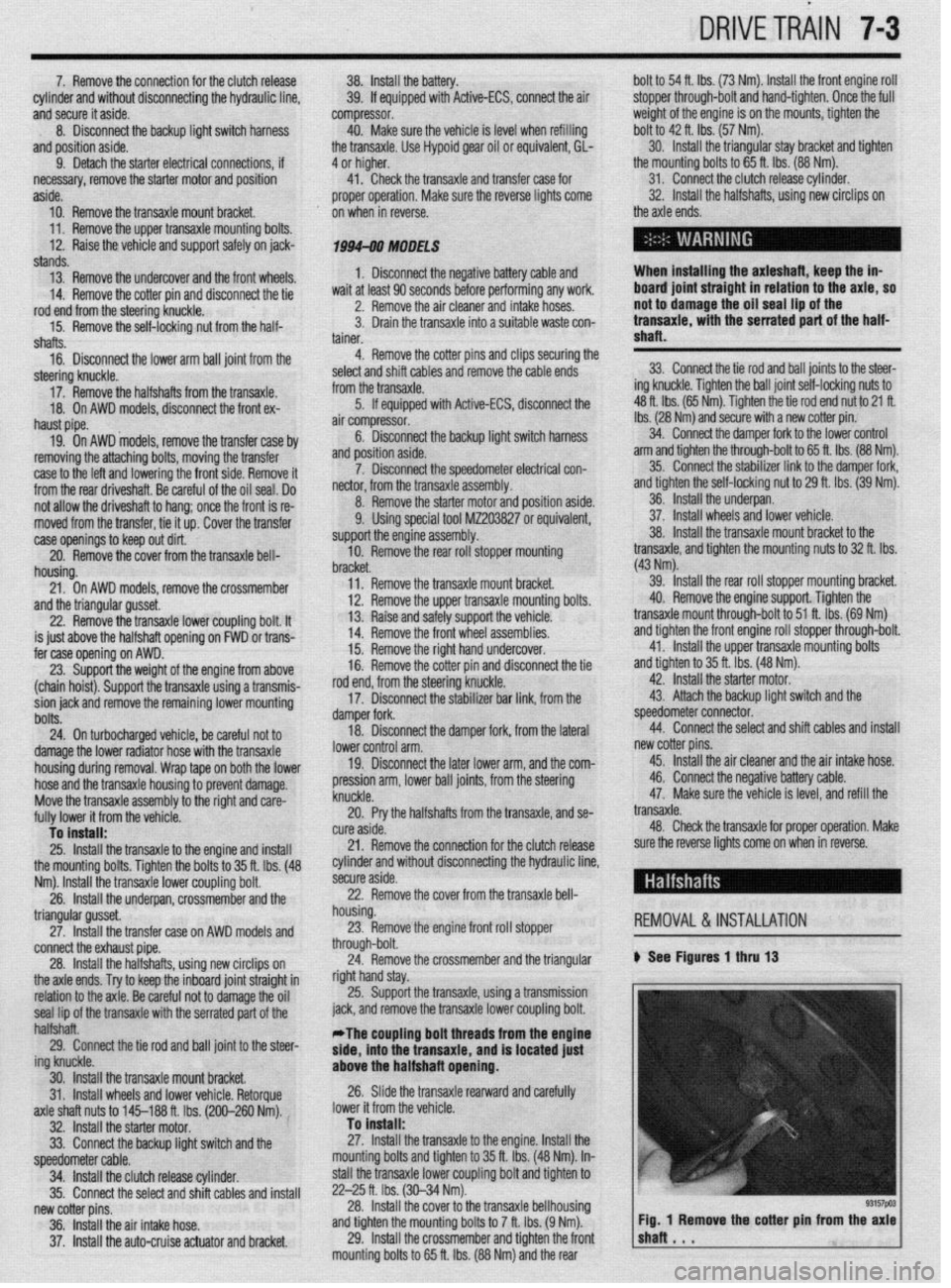
Install the transfer case on AWD models and 23. Remove the engine front roll stopper REMOVAL&INSTALLATION
connect the exhaust pipe. through-bolt.
28.
Install the halfshafts, using new circlips on 24. Remove the crossmember and the triangular ) See Figures 1 thru 13
the axle ends. Try to keep the inboard joint straight in right hand stay.
relation to the axle. Be careful not to damage the oil 25. Support the transaxle, using a transmission
seal lip of the transaxle with the serrated part of the jack, and remove the transaxle lower coupling bolt.
halfshaft.
29. Connect the tie rod and ball joint to the steer- *The coupling bolt threads from the englne
side, into the transaxle, and is located just
ing knuckle.
30. Install the transaxle mount bracket. above the halfshaft opening.
31. Install wheels and lower vehicle. Retorque 26. Slide the transaxle rearward and carefully
axle shaft nuts to 145-188 ft. Ibs. (200-260 Nm). lower it from the vehicle.
32. Install the starter motor. To install:
33. Connect the backup light switch and the 27. Install the transaxle to the engine. Install the
speedometer cable. mounting bolts and tighten to 35 ft. Ibs. (48 Nm). In-
34. Install the clutch release cylinder. stall the transaxle lower coupling bolt and tighten to
35.
Connect the select and shift cables and install 22-25 ft. Ibs. (30-34 Nm).
new cotter pins. 28. Install the cover to the transaxle bellhousing
36. Install the air intake hose. and tighten the mounting bolts to 7 ft. Ibs. (9 Nm).
37. Install the auto-cruise actuator and bracket. 29. Install the crossmember and tighten the front
mounting bolts to 65 ft. Ibs. (88 Nm) and the rear