1900 MITSUBISHI DIAMANTE dead battery
[x] Cancel search: dead batteryPage 5 of 408
1-6 GENERALINFORMATIONAND MAINTENANCE
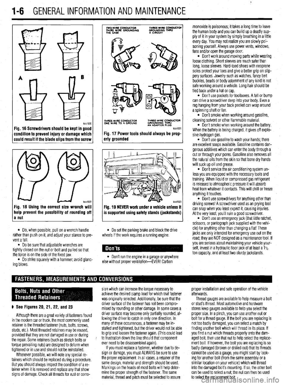
Fig. 16 Screwdrivers should be kept in good
:ondition to prevent injury or damage which
:ould result it the blade slips from the screw
0
0
PP tccs1022 Fig. 16 Using the correct size wrench will
help prevent the possibility of rounding off
a nut
7
lwo.WIRE CouDuClOR TMREE-WIRE CONO”CTOI
MIRD WIRE GROUNDING GROUNDING TNRU
THE CASE A CmxlIT
.
i$Y$$pQ
p-+
TNHREE-WIRE CONDUCTOR THREE-WIRE CONDUCTOR
ONE WIRE TO 4 GROUND GROUNOlNG TMRU
AN ADAPTER PLUG
tccm21
Fig. 17 Power tools should always be prop-
erly grounded
Fig. 19 NEVER work under a vehicle unless it
is supported using safety stands (jackstands)
l Do, when possible, pull on a wrench handle l Do set the parking brake and block the drive
rather than push on it, and adjust your stance to pre-
vent a fall. wheels if the work requires a running engine.
l Do be sure that adjustable wrenches are
tightly closed on the nut or bolt and pulled so that
the force is on the side of the fixed jaw.
l Do strike squarely with a hammer; avoid glanc-
ing blows. l Don’t run the engine in a garage or anywhere
else without proper ventilation-EVER! Carbon monoxide is poisonous; it takes a long time to leave
the human body and you can build up a deadly sup-
ply of it in your system by simply breathing in a !ittle
every day. You may not realize you are slowly poi-
soning yourself. Always use power vents, windows,
fans and/or open the garage door.
l Don’t work around moving parts while wearing
loose clothing. Short sleeves are much safer than
long, loose sleeves. Hard-toed shoes with neoprene
soles protect your toes and give a better grip on slip-
pery surfaces. Jewelry such as watches, fancy belt
buckles, beads or body adornment of any kind is not
safe working around a vehicle. Long hair should be
tied back under a hat or cap.
l Don’t use pockets for toolboxes. A fall or bump
can drive a screwdriver deep into your body. Even a
rag hanging from your back pocket can wrap around
a spinning shaft or fan.
l Don’t smoke when working around gasoline,
cleaning solvent or other flammable material.
l Don’t smoke when workrng around the battery.
When the battery is being charged, it gives off explo-
sive hydrogen gas.
l Don’t use gasoline to wash your hands; there
are excellent soaps available. Gasoline contains dan-
gerous additives which can enter the body through a
cut or through your pores. Gasoline also removes all
the natural oils from the skin so that bone dry hands
will suck up oil and grease.
l Don’t service the air conditioning system un-
less you are equipped with the necessary tools and
trainmg. When liquid or compressed gas refrigerant
is released to atmospheric pressure it will absorb
heat from whatever it contacts. This will chill or freeze
anything it touches.
l Don’t use screwdrivers for anything other than
driving screws! A screwdriver used as an prying tool
can snap when you least expect it, causing injuries.
At the very least, you’ll ruin a good screwdriver.
. Don’t use an emergency jack (that little ratchet,
scissors, or pantograph jack supplied with the vehi-
cle) for anything other than changing a flat! These
jacks are only Intended for emergency use out on the
road; they are NOT designed as a maintenance tool. If
you are serious about mamtaining your vehicle your-
self, invest in a hydraulic floor jack of at least a 1%
ton capacity, and at least two sturdy jackstands.
sion which can increase the torque necessary to proper installation and safe operation of the vehicle
achieve the desired clamp load for which that fastener afterwards.
was originally selected. Additionally, be sure that the Thread gauges are available to help measure a bolt
p See Figures 20, 21, 22, and 23 driver surface of the fastener has not been compro- or stud’s thread. Most automotive and hardware
mised by rounding or other damage. In some cases a stores keep gauges available to help you select the
Although there are a great variety of fasteners found driver surface may become only partially rounded, al- proper size. In a pinch, you can use another nut or
in the modern car or truck, the most commonly used lowing the driver to catch in only one direction. In bolt for a thread gauge. If the bolt you are replacing is
retainer is the threaded fastener (nuts, bolts, screws, many of these occurrences, a fastener may be in- not too badly damaged, you can select a match by
studs, etc.). Most threaded retainers may be reused, stalled and tightened, but the driver would not be able finding another bolt which will thread in its place. If
provided that they are not damaged in use or during to grip and loosen the fastener again. (This could lead you find a nut which threads properly onto the dam-
the repair. Some retainers (such as stretch bolts or J to frustration down the line should that component aged bolt, then use that nut to help select the replace-
torque prevailing nuts) are designed to deform when ever need to be disassembled again). ment bolt If however, the bolt you are replacing is so
tightened or in use and should not be reinstalled. If you must replace a fastener, whether due to de- badly damaged (broken or drilled out) that its threads
Whenever possible, we will note any special re- sign or damage, you must ALWAYS be sure to use cannot be used as a gauge, you might start by look-
tainers which should be replaced during a procedure. the proper replacement In all cases, a retainer of the ing for another bolt (from the same assembly or a
But you should always inspect the condition of a re- same design, material and strength should be used. similar location on your vehicle) which will thread
tainer when It is removed and replace any that show Markings on the heads of most bolts will help deter- into the damaged bolt’s mounting. If so, the other bolt
signs of damage. Check all threads for rust or corro- mine the proper strength of the fastener. The same
can be used to select a nut; the nut can then be used
material, thread and pitch must be selected to assure
to select the replacement bolt.
Page 17 of 408
l
1-18 GENERALINFORMATIONAND MAINTENANCE
the clamps and remove the cables, negative cable
first. On batteries with posts on top, the use of a
puller specially made for this purpose is recom-
mended. These are inexoensive and available in most alternator or turn the adjusting bolt to adjust belt ten-
sion. Once the desired value is reached, secure the
bolt or locknut and recheck tension.
d”t” lJdlL> X”lt;>. 31°C LtXlllllldl lJdllt2)’ MLJIC, dlt’ X- cured with a small bolt. ST& I REMOVAL &INSTALLATION
Clean the cable clamps and the battery terminal I
with a wire brush, until all corrosion, grease, etc., is
removed and the metal is shinv. It is esneciallv imnnr-
tant to c
knife is useful nere), since a smart
material or oxidation there will pre Clean the cable clamps and the battery terminal
with a wire brush, until all corrosion, grease, etc., is
removed and the metal is shiny. It is especially impor-
tant to clean the inside of the clamp thoroughly (an old
knife is useful here), since a small deposit of foreign
material or oxidation there will prevent a sound electri-
cal connection and inhibit either starting or charging.
Special tools are available for cleaning these parts,
one type for conventional top post batteries and an-
other type for side terminal batteries. It is also a good
idea to apply some dielectric grease to the terminal, as
this will aid in the prevention of corrosion,
After the clamps and terminals are clean, reinstall
the cables, negative cable last; DO NOT hammer the
clamps onto battery posts. Tighten the clamps se-
curely, but do not distort them. Give the clamps and
terminals a thin external coating of grease after in-
stallation, to retard corrosion.
Check the cables at the same time that the terminals
are cleaned. If the cable insulation is cracked or bro-
ken, or if the ends are frayed, the cable should be re-
placed with a new cable of the same length and gauge.
CHARGING
the cables, negative cable last; DO NOT hammer the
curely, but do not distort them. Give the clamps and
terminals a thin external coating of grease after in-
stallation, to retard corrosion.
Check the cables at the same time that the terminals
are cleaned. If the cable insulation is cracked or bro-
ken, or if the ends are frayed, the cable should be re-
placed with a new cable of the same length and aauae.
CHARGING
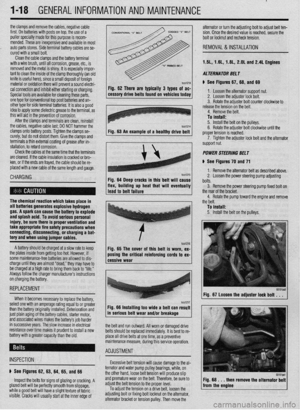
Fig. 62 mere are typically 3 types of ac-
cessory drive belts found on vehicles today 1. Loosen the alternator support nut.
2. Loosen the adjuster lock bolt.
3. Rotate the adjuster bolt counter clockwise to
I .I , . . . * . .
I Tn i”et*ll* Fig. 62 There are typically 3 types of ac-
Fig. 64 Deep cracks in this belt will cause
flex, building up heat that will eventually 11, 1.8L, 2.OL and 2.4L Engines
cal connection and inhibit either starting or charging.
Special tools are available for cleaning these parts,
one type for conventional top post batteries and an-
other type for side terminal batterin, I+ if QI@* 3 nnnd
idea to apply some dielectric grr
this will aid in the prevention of ,,vIIuaIUII.
After the clamps and terminals are clean, reinstall 1.5L, 1.6
AL TERNA TOR BE1 T
e See Figures 67,68, and 69
1. Loosen the alternator support nut.
2. Loosen the adjuster lock bolt.
3. Rotate the adjuster bolt counter clockwise to
release the tension on the belt.
4. Remove the belt.
To install:
5. Install the belt on the pulleys.
6. Rotate the adjuster bolt clockwise until the
proper tension is reached.
7. Tighten the adjuster lock bolt and the alternator
support nut.
POWER STEERING BELT
8 See Figures 70 and 71
1. Remove the alternator belt as described above.
2. Loosen the power steering pump adjusting
bolts.
3. Remove the power steering oumo fixed bolt on
R Rntatn the cxiillrtm hnit A&+,& until the r -r- .- .- ._.. ._ .______
7. Tighten the adjuster lock bolt and the alternator
support nut.
POWER STEERING BELT
1 ..“‘.I ““..Y...Y up II”“. ..IU. ..m.*
1 lead to belt failure V.
I
I
The chemical reaction which takes place in - 1 the rear of the bracket.
4. Rotate the pump toward the engine and remove
the belt.
all batteries generates explosive hydrogen
gas. A spark can cause the battery to explode
and splash acid. To avoid serious personal
injury, be sure there is proper ventilation and
take appropriate fire safety precautions when
connecting, disconnecting, or charging a bat-
tery and when using jumper cables. To fnstall:
5. Install the belt on the pulleys.
A battery should be charged at a slow rate to keep
the plates inside from getting too hot. However, if
some maintenance-free batteries are allowed to dis-
charge until they are almost “dead,” they may have to
be charged at a high rate to bring them back to “life.”
Always follow the charger manufacturers instructions
on charging the battery. 85 The cover of this belt ex-
Fig. is worn,
REPLACEMENT
When it becomes necessary to reolace thn haeoN
‘” yyL’“‘J’ I or oreMer
select one with an amperage rating equal tc .
a ----
than the battery originally installed. Deterioration and
just plain aging of the battery cables, starter motor,
and associated wires makes the battery’s job harder
in successive years. The slow increase in electrical
resistance over time makes it prudent to install a new
battery with a greater capacity than the old. 1 Fig. 67 Loosen the adjuster lock bolt . . .
I ‘-
I -. -_ tm1217 Fig. 66 Installing too wide a belt can resylt
in serious belt wear and/or breakage
the belt and run outward. All worn or damaged drive
belts should be replaced immediately. It is best to re-
place all drive belts at one time, as a preventive
uring this service operation. maintenance measure, d
- ADJUSTMENT : *
INSPECTION Excessive belt tension will cause damage to the al-
e See Figures 62, 83, 64, 65, and 88
Inspect the belts for signs of glazing or cracking. A
glazed belt will be perfectly smooth from slippage,
while a good belt will have a slight texture of fabric
visible. Cracks will usually start at the inner edge of pulley bearings, while, on
It tension will
Droduce slin ternator and water pump
the other hand, loose be
r ------ r
and premature wear on the belt. Therefore, be sure to
adjust the belt tension to the proper level.
To
adjust the tension ’ ’ ’ ” ’ ‘* adjusting bolt or fixing b
alternator bracket or tens on a onve Den. loosen me I Fig. 68 . . . then
from the engine remove the alternator
bolt locknut on the alternator,
iion pulley. Then move the
Page 24 of 408
GENERALINFORMATIONAND MAlNTENANdE 1-25
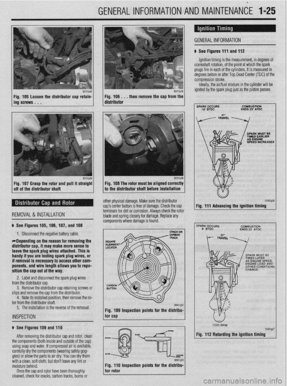
osen the distributor cap retain-
Fig. 106. . . then remove the cap from the
distributor
Fig. 107 Grasp the rotor and pull it straight
off of the distributor shaft
REMOVAL &INSTALLATION
1. Disconnect the negative battery cable.
*Depending on the reason for removing the
distributor cap, it may make more sense to Fig. 108 The rotor must be aligned correctly
to the distributor shaft before installation
other physical damage. Make sure the distributor
cap’s center button is free of damage. Check the cap
terminals for dirt or corrosion. Always check the rotor
blade and spring closely for damage. Replace any
comoonents where damaae is found.
smmE
ALGNME
LOCATOR
b See Figures 105,106,107, and 108 GENERAL INFORMATION
b See Figures 111 and 112
Ignition timing is the measurement, in degrees of
crankshaft rotation, of the point at which the spark
plugs fire in each of the cylinders. It is measured in
degrees before or after Top Dead Center (TDC) of the
compression stroke.
Ideally, the air/fuel mixture in the cylinder will be
ignited by the spark plug just as the piston passes
I 1 COMBUSTION
ENDS 23’ ATDC
SPEED INCREASES
9ir&1$?6
Fig. 111 Advancing the ignition timing
’
CCURS
COMBUSTION
DC
ENDS 23 ATDC
3. Remove the distributor cap retaining screws or
clips and remove the cap from the distributor.
4. Note its installed position, then remove the ro-
tor from the distributor shaft. leave the spark plug wires attached. This is
handy if you are testing spark plug wires, or
if removal is necessary to access other com-
ponents, and wire length allows you to repo-
sition the cap out of the way.
2. Label and disconnect the spark plug wires
from the distributor cao.
5. The installation is the reverse of the removal.
INSPECTION
u See Figures 109 and 110
9mg27
After removing the distributor cap and rotor, clean
the components (both inside and outside of the cap)
using soap and water. If compressed air is available,
carefully dry the components (wearing safety gog-
gles) or allow the parts to air dry. You can dry them
with a clean, soft cloth, but don’t leave any lint or
moisture behind.
Once the cap and rotor have been thoroughly Inspection points for the dis Fig. 112 Retarding the tgnttion timing
cleaned, check for cracks, carbon tracks, burns or
Page 26 of 408
GENERALINFORMATIONAND MAlNTENANdE I-27
ADJUSTMENT
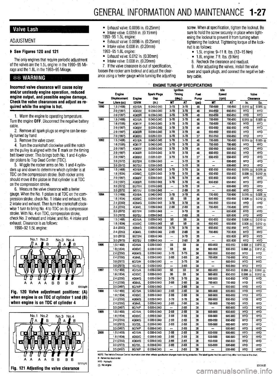
u See Figures 120 and 121
The only engines that require periodic adjustment
of the valves are the 1.5L engine in the 1990-95 Mi-
rage and the 1.8L in the 1993-95 Mirage.
Incorrect valve clearance will cause noisy
and/or unsteady engine operation, reduced
engine output, and possible engine damage.
Check the valve clearances and adjust as re-
quired while the engine is hot.
1. Warm the engine to operating temperature.
Turn the engine OFF. Disconnect the negative battery
cable.
2. Remove all spark plugs so engine can be eas-
ily turned by hand
3. Remove the valve cover.
4. Turn the crankshaft clockwise until the notch
on the pulley is aligned with the
T mark on the timing
belt lower cover. This brings both No. 1 and 4 cylin-
der pistons to Top Dead Center (TDC).
5. Wiggle the rocker arms on No. 1 and 4 cylin-
ders up and down to determine which cylinder is at
TDC on the compression stroke. Both rocker arms
should move if the piston in that cylinder is at TDC
on the compression stroke.
6. Measure the valve clearance with a feeler
gauge. When the No. 1 piston is at TDC on the com-
pression stroke, check No. 1 intake and
exhaust; No.
2 intake and exhaust. Then turn the crankshaft clock-
wise 1 turn to bring No. 4 to TDC on its compression
stroke. With No. 4 on TDC, compression stroke,
check No. 2 exhaust and intake; and No. 4 intake and
exhaust. Clearance is as follows:
1990-92 1.5L engine:
No.1 No.2
No.3 No.4
when engine is on TDC of cylinder 1 and (B) when engine is on TDC of cylinder 4
No.1 No.2
No.3 No.4
AA AA BB BB
93151g10 Fig. 121 Adjusting the valve clearance
l Exhaust valve: 0.0098 in. (0.25mm) screw. When at specification, tighten the locknut. Be l Intake valve: 0.0059 in. (0.15mm)
1993-95 1.5L engine: sure to hold the screw securely in place when tight-
l Exhaust valve: 0.0098 in. (0.25mm) ening the locknut to prevent it from turning when
* Intake valve: 0.008 in. (0.20mm) tightening the locknut. Tightening torque of the lock-
nut is as follows:
1993-95 1.8L engine:
l Exhaust valve: 0.012 in. (0.30mm) l 1.5L engine: 9-11 ft. Ibs. (12-15 Nm)
l Intake valve: 0.008 in. (0.20mm) l 1.8L engine: 7 ft. Ibs. (9 Nm)
8. Recheck the clearance and readjust.
7. If the valve clearance is out of specification,
9. After adjusting the valves, install the valve
loosen the rocker arm locknut and adjust the clear-
ante using a feeler gauge while turning the adjusting cover and spark plugs, and connect the negative bat-
tery cable.
Engine
ENGINE TUNE-UP SPECIFICATIONS Ignition
Spark Plugs liming
Fuel Idle
Speed Valve
Displacement
Engine
Gap (as.) Pump (rpm)
Clearance
Page 45 of 408
.
I-46 GENERALINFORMATIONAND MAINTENANCE
2. Pull the jumping vehicle (with the good bat-
tery) into a position so the jumper cables can reach
the dead battery and that vehicle’s engine. Make sure
that the vehicles do NOT touch.
3. Place the transmissions/transaxles of both ve-
hicles in Neutral (MT) or P (AT), as applicable, then
firmly set their parking brakes.
*ff necessary for safety reasons, the hazard
lights on both vehicles may be operated
throughout the entire procedure without sig-
nificantiy increasing the diff icuity of jumping
the dead battery.
4. Turn all lights and accessories OFF on both
vehicles. Make sure the ignition switches on both ve-
hicles are turned to the OFF position.
5. Cover the battery cell caps with a rag, but do
not cover the terminals.
6. Make sure the terminals on both batteries are
clean and free of corrosion or proper electrical con-
nection will be impeded. If necessary, clean the bat-
tery terminals before proceeding.
7. Identify the positive (+) and negative (-) termi-
nals on both batteries.
8. Connect the first jumper cable to the positive
(t) terminal of the dead battery, then connect the
other end of that cable to the positive (t) terminal of
the booster (good) battery.
9. Connect one end of the other jumper cable to
the negative (−) terminal on the booster bat-
tery and the final cable clamp to an engine bolt head,
alternator bracket or other solid, metallic point on the
engine with the dead battery. Try to pick a ground on
the engine that is positioned away from the battery in
order to minimize the possibility of the 2 clamps
touching should one loosen during the procedure.
DO NOT connect this clamp to the negative (-) termi-
nal of the bad battery. cable on the donor battery. Disconnect the positive
cable from the donor battery and finally, disconnect
the positive cable from the formerly dead battery. Be
careful when disconnecting the cables from the posi-
tive terminals not to allow the alligator clips to touch
any metal on either vehicle or a short and sparks will
occur.
I
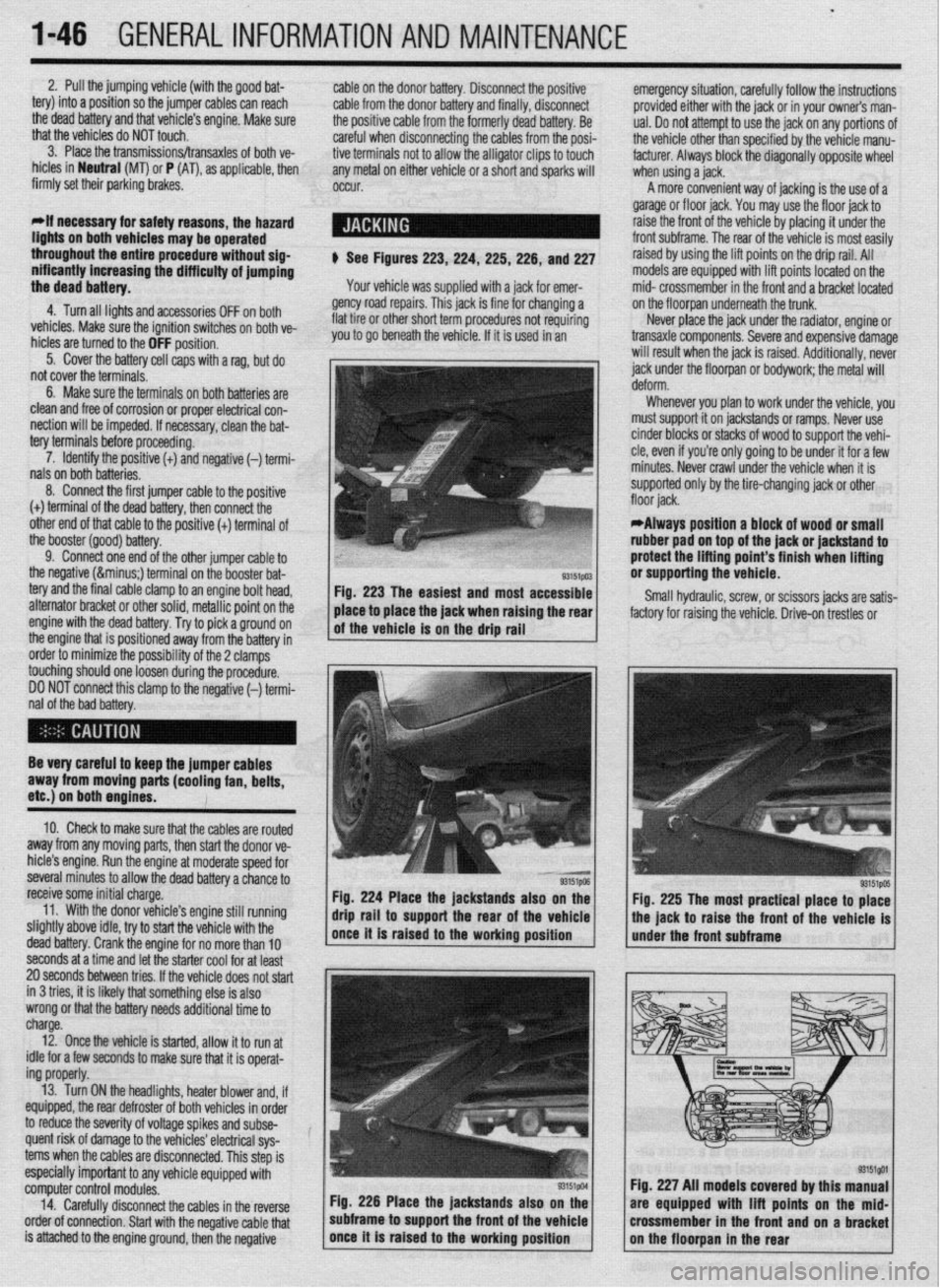
$ See Figures 223,224, 225,226, and 227
Your vehicle was supplied with a jack for emer-
gency road repairs. This jack is fine for changing a
flat tire or other short term procedures not requiring
you to go beneath the vehicle. If it is used in an emergency situation, carefully follow the instructions
provided either with the jack or in your owners man-
ual. Do not attempt to use the jack on any portions of
the vehicle other than specified by the vehicle manu-
facturer. Always block the diagonally opposite wheel
when using a jack.
A more convenient way of jacking is the use of a
garage or floor jack. You may use the floor jack to
raise the front of the vehicle by placing it under the
front subframe. The rear of the vehicle is most easily
raised by using the lift points on the drip rail. All
models are equipped with lift points located on the
mid- crossmember in the front and a bracket located
on the floorpan underneath the trunk.
Never place the jack under the radiator, engine or
transaxle components. Severe and expensive damage
will result when the jack is raised. Additionally, never
jack under the floorpan or
bodywork; the
metal will
Whenever you plan to work under the vehicle, you
must support it on jackstands or ramps. Never use
cinder blocks or stacks of wood to support the vehi-
cle, even if you’re only going to be under it for a few
minutes. Never crawl under the vehicle when it is
supported only by the tire-changing jack or other
*Always position a block of wood or small
rubber pad on top of the jack or jackstand to
protect the lifting point’s finish when lifting
or supporting the vehicle.
Small hydraulic, screw, or scissors jacks are satis-
factory for raising the vehicle. Drive-on trestles or
Be very careful to keep the jumper cables
away from moving parts (cooling fan, belts,
etc.) on both engines.
10. Check to make sure that the cables are routed
away from any moving parts, then start the donor ve-
hicle’s engine. Run the engine at moderate speed for
several minutes to allow the dead battery a chance to
receive some initial charge.
11. With the donor vehicle’s engine still running
slightly above idle, try to start the vehicle with the
dead battery. Crank the engine for no more than 10 &stands also on the
Fig. 225 The most practical place to place
front of the vehicle is
seconds at a time and let the starter cool for at least
20 seconds between tries. If the vehicle does not start
in 3 tries, it is likely thatsomething else is also
wrong or that the battery needs additional time to
charge.
12. Once the vehicle is started, allow it to run at
idle for a few seconds to make sure that it is operat-
ing properly.
13. Turn ON the headlights, heater blower and, if
equipped, the rear defroster of both vehicles in order
to reduce the severity of voltage spikes and subse-
quent risk of damage to the vehicles’ electrical sys-
tems when the cables are disconnected. This step is
especially important to any vehicle equipped with
computer control modules.
14. Carefully disconnect the cables in the’reverse
order of connection. Start with the negative cable that
is attached to the engine ground, then the negative Fig. 226 Place the jackstands also
subframe to support the front of the Fig. 227 All models covered by this
are equipped with lift points on t
crossmember in the front and on a
Page 51 of 408
2-4 ENGINEELECTRICAL
2. Install the distributor in the engine so the rotor
is aligned with the matchmark on the housing and the
housing is aligned with the matchmark on the engine.
4.‘ Remove the retaining screws and coil from en-
gine.
5. Installation is the reverse of the removal proce-
dure. Before removing the distributor, position No. 1
‘cylinder at Top Dead Center (TDC) on the compres-
sion stroke and align the timing marks.
1. Disconnect the negative battery cable.
2. Remove the ignition wire cover, if equipped.
3. Detach the distributor harness connector.
4. Remove the distributor cap with all ignition wires
still connected. Remove the coil wire, if necessary.
5. Matchmark the rotor to the distributor housing
and the distributor housing to the engine.
6. Remove the hold-down nut.
7. Carefully remove the distributor from the engine.
INSTALLATION
6 See Figures 19 and 2g
Timing Not Disturbed
1, Install a new distributor housing O-ring and 4. Attach the distributor harness connectors.
5. Install the distributor cap.
6. Connect the negative battery cable.
7. Adjust the ignition timing and tighten the hold-
down nut to 6 ft. Ibs. (11 Nm).
Timing Dlsturbed
1. Install a new distributor housing O-ring and
lubricate with clean oil.
2. Position the engine so the No. 1 piston is at
Top Dead Center (TDC) of its compression stroke
and the mark on the vibration damper is aligned with
REMOVALS& INSTALLATION lubricate with clean oil. 0 on the timing indicator.
3. Align the distributor housing and gear mating
marks. Install the distributor in the engine so the slot
or groove of the distributor’s installation flange aligns
with the distributor installation stud in the engine
block. Be sure the distributor is fully seated. Inspect
alignment of the distributor rotor making sure the ro- tnr ic dinnnd with thn qn,c$nn of the Nn innitinn
ISL, 1 AIL, 2.4L, and 3.5L Engines
The power transistor (ignition module) is an inte-
gral part of the distributor.
2.gL SDHC and 3.OL SOHC Engines
# See Figure 14
1 x Disconnect the negative battery cable.
Remove the retaining screws and power tran-
Detach the connectors from the dis- Fig. 16 Remove the bolt holding the wire
harness and capacitor, then move the har-
ness and capacitor to the side
Fig. 18 . . . then slide the distributor from
the engine
/ tion’s-3.gL SOHC engine g3is~@ 1 Fig 14 Ignition system component loca-
Page 52 of 408
ENGlNEELECTRliAL 2-5
Fig. 19 Adjusting the distributor-1.5L en-
gine shown, others similar
4. Install the hold-down nut.
5. Attach the distributor harness connectors.
6. Install the distributor cap.
7. Connect the negative battery cable.
8. Adjust the ignition timing and tighten the hold-
down nut to 8 ft. Ibs. (11 Nm).
For procedures on the position sensors, please re-
fer to Section 4 in this manual.
The ignition system found on the 1.6L, 1997-60
1.8L, 2.OL DOHC, 1999-00 2.4L SOHC, 2.4L DOHC,
and 3.OL DOHC engines is a distributorless type.
The advance of this system, like the distributor type
ignition, is controlled by the Engine Control Unit
(ECU) or Powertrain Control Module (PCM). The
distributorless ignition system contains a crank an-
gle/position sensor which detects the crank angle or
position to each cylinder and converts this data into
pulse signals. These signals are sent to the
ECLVPCM, which calculates the engine rpm and
regulates the fuel injection and ignition timing ac-
cordingly. The system also contains a top dead cen-
ter sensor which detects the top dead center position
of each cylinder and converts this data into pulse
signals. These signals are then sent to the
ECU/PCM, which calculates the sequence of fuel in-
jection and engine rpm.
When the ignition switch is turned ON, battery
voltage is applied to the ignition coil primary wind-
ing. As the crank angle sensor shaft rotates, ignition
signals are transmitted from the multi port injection
control unit to the power transistor. These signals
activate the power transistor to cause ignition coil
primary winding current to flow from the ignition
coil negative terminal through the power transistor
to ground or be interrupted, repeatedly. This action
induces high voltage in the secondary winding of
the ignition coil. From the ignitron coil, the sec-
ondary winding current produced flows through the
spark plug to ground, thus causing ignition in each
cylinder.
Refer to Diagnosis and Testing under Distributor
Ignition in this section,
There are no adjustments to the distributorless ig-
nition system other than the ignition timing adjust-
ment. Refer to section 1 for ignition timing adjust-
ment.
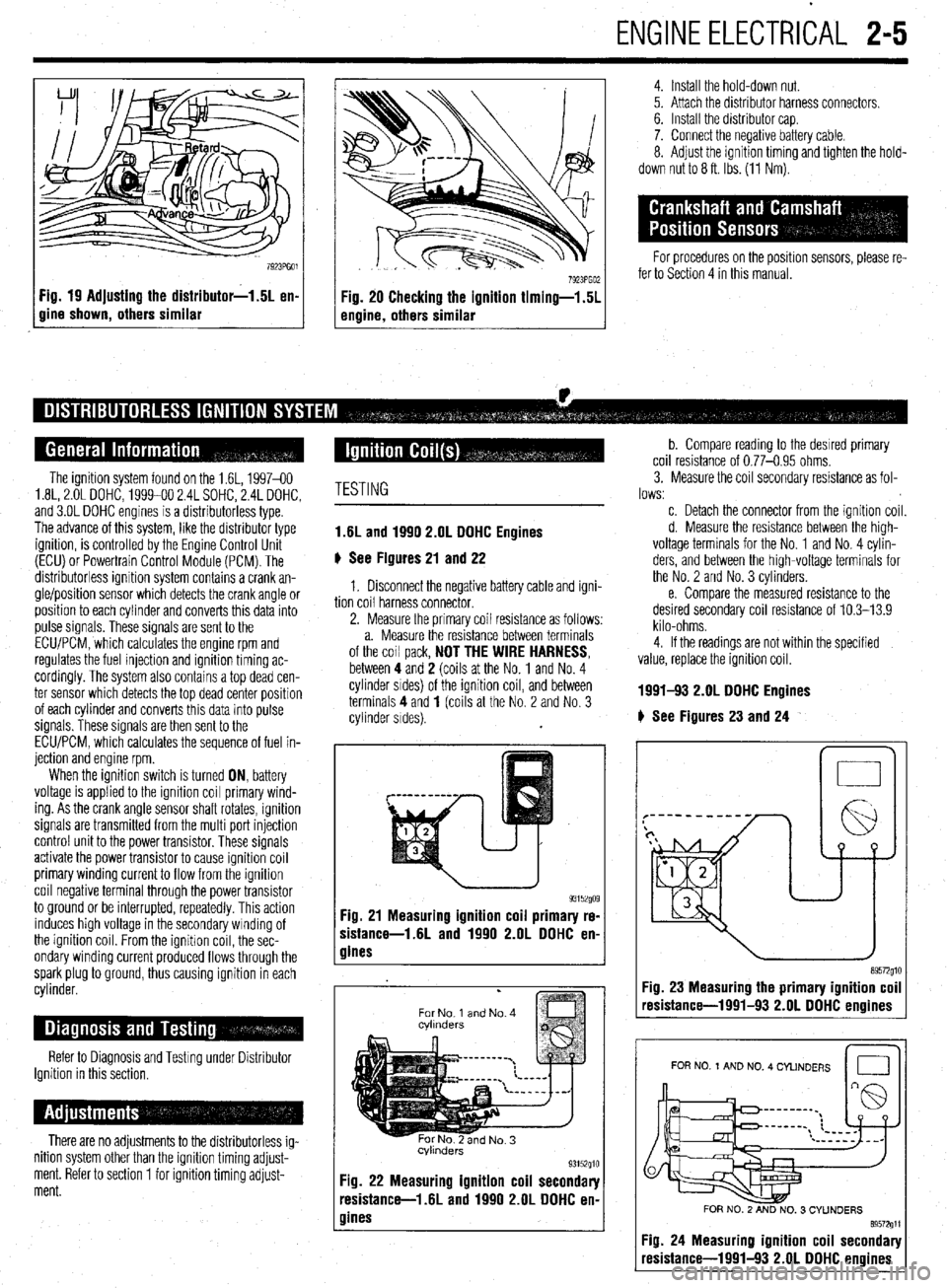
TESTING
1.6L and 1990 2.OL DOHC Engines
6 See Figures 21 and 22
1. Disconnect the negative battery cable and igni-
tion coil harness connector.
2. Measure the primary coil resistance as follows:
a. Measure the resistance between terminals
of the coil pack,
NOT THE WIRE HARNESS, between 4 and 2 (coils at the No. 1 and No. 4
cylinder srdes) of the ignition coil, and between
terminals 4 and
1 (coils at the No. 2 and No. 3
cylinder sides).
93152go9 Fig. 21 Measuring ignition coil primary re-
sistance-1.6L and 1990 2.OL DDHC en-
gines
.
For No 1 and No. 4
cvlmders
Fig. 22 Measuring ignition coil secondary
resistance-l .6L and 1990 2.OL DOHC en-
gines
b. Compare reading to the desrred primary
coil resistance of 0.77-0.95 ohms.
3. Measure the coil secondary resistance as fol-
lows:
c. Detach the connector from the ignition coil.
d. Measure the resistance between the high-
voltage terminals for the No. 1 and No. 4 cylin-
ders, and between the high-voltage terminals for
the No. 2 and No. 3 cylinders.
e. Compare the measured resistance to the
desired secondary coil resistance of 10.3-13.9
kilo-ohms.
4. If the readings are not within the specified
value, replace the ignition coil.
1991-!I3 2.OL DDHC Engines
# See Figures 23 and 24
n 0
Fig. 23 Measuring the primary ignition coil
resistance-1991-93 2.OL DOHC enoines
I I
FOR NO 1 AND NO. 4 CYLINDERS
Id
FOR NO. 2 AND NO. 3 CYUNDERS
89572611
Fig. 24 Measuring ignition coil secondary
resistance-1991-93 2.OL DOHC engines
Page 95 of 408
3-34 ENGINEANDENGINEOVERHAUL
9. Remove the front cover mounting bolts. Note
the lengths of the mounting bolts as they are re-
moved for proper installation.
10. Remove the front case assembly and oil
pump assembly.
11. Remove the oil pump cover.
12. Remove the inner and outer gears from the
front case.
To install 13. Remove all gasket material from the mating
surfaces and clean all parts.
14. Thoroughly coat both oil pump gears with
clean engine oil and install them in the correct direc-
tion of rotation.
15. Install the pump cover and tighten the bolts to
84 inch Ibs. (10 Nm).
16. Coat the relief valve and spring with clean en-
gine oil. Install them and tighten the plug to 33 ft.
Ibs. (45 Nm).
17. Install a new front crankshaft seal and coat
the lips of the seal with clean engine oil.
18. Install the front case and oil pump assembly
to the engine block using a new gasket. Tighten the
bolts to loft. Ibs. (14 Nm)
19. Install the oil screen with new gasket. Torque
the screen bolts to 14 ft. Ibs. (19 Nm).
20. Install the oil pan.
21. Install the crankshaft sprocket and timing
belt. Refer to the timing belt procedure in this sec-
tion.
22. Fill the crankcase to the proper level.
Operating the engine without the proper
amount and type of engine oil will result in
severe enoine damaae.
23. Connect the negative battery cable.
1.6L, 2.OL and 2.4L Engines
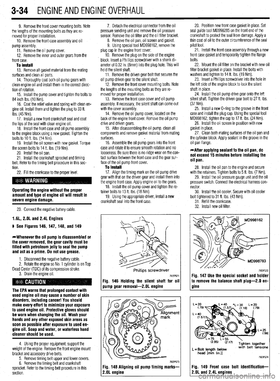
p See Figures 146, 147, 148, and 149
*Whenever the oil pump is disassembled or
the cover removed, the gear cavity must be
filled with petroleum jelly to seal the pump
and act as a prime. Do not use grease.
1. Disconnect the negative battery cable.
2. Rotate the engine so No. 1 cylinder is on Top
Dead Center (TDC) of its compression stroke.
3. Drain the engine oil.
The EPA warns that prolonged contact with
used engine oil may cause a number of skin
disorders, including cancer! You should
make every effort to minimize your exposure
to used engine oil. Protective gloves should
be worn when changing the oil. Wash your
hands and any other exposed skin areas as
soon as possible afler exposure to used en-
gine oil. Soap and water, or waterless hand
cleaner should be used.
4 Using the proper equipment, support the
weight of the engine Remove the front engine mount
bracket and accessory drive belts.
5 Remove timing belt upper and lower covers.
6. Remove the timing belt and crankshaft
sprocket. Refer to the timing belt procedure in this
section. 7. Detach the electrical connector from the oil
pressure sending unit and remove the oil pressure
sensor. Remove the oil filter and the oil filter bracket.
8. Remove the oil pan, oil screen and gasket.
9. Using special tool MD998162, remove the
plug cap in the engine front cover.
10. Remove the plug on the side of the engine
block. Insert a Phrllips screwdriver with a shank di-
ameter of 0.32 in. (8mm) into the plug hole. This will
hold the silent shaft.
11. Remove the driven gear bolt that secures the
oil pump driven gear to the silent shaft.
12. Remove the front cover mounting bolts. Note
the lengths of the mounting bolts as they are re-
moved for proper installation.
13. Remove the front case cover and oil pump
assembly. If necessary, the silent shaft can come out
with the cover assembly.
14. Remove the oil pump cover, located on the
back of the engine front cover. Remove the oil pump
drive and driven gears.
15. After disassembling the oil pump, clean all
components and remove gasket material from mating
surfaces.
16. Assemble the oil pump gears into the front
case and rotate it to ensure smooth rotation and no
looseness. Be sure there is no ridge wear on the con-
tact surface between the front case and the gear sur-
face of the oil pump front cover.
To install 17. Align the timing mark on the oil pump drive
gear with that on the driven gear and install them into
the engine front case. Apply engine 011 to the gears.
18. Install the oil pump cover and tighten the re-
tainer bolts to 13 ft. Ibs. (18 Nm).
19. Using the appropriate driver, install a new
crankshaft seal into the front case.
Phrllips screwdrrver
7923PG71 Fig. 146 Holding the silent shaft for oil
pump gear removal-2.01 engine
7923PG73 Fig. 148 Aligning oil pump timing marks-
2.OL ermine
20. Position new front case gasket in place. Set
seal guide tool MD998285 on the front end of the
crankshaft to protect the seal from damage. Apply a
thin coat of oil to the outer circumference of the seal
pilot tool.
21. Install the front case assembly through a new
front case gasket and temporarily tighten the flange
bolts.
22. Mount the oil filter on the bracket with new oil
filter bracket gasket in place. Install the bolts with
washers and tighten to 14 ft. Ibs. (19 Nm).
23. Insert a Phillips screwdriver into the hole in
the left side of the engine block to lock the silent
shaft in place.
24. Install the oil pump drive gear onto the left
silent shaft. Tighten the driven gear bolt to 27 ft. Ibs.
(37 Nm).
25. Install a new O-ring to the groove in the front
case and install the plug cap. Using the special tool
MD998162, tighten the cap to 17 ft. Ibs. (24 Nm).
26. Install the oil screen in position with new
gasket in place.
27. Clean both mating surfaces of the oil pan and
the cylinder block. Apply sealant In the groove in the
oil pan flange.
*After applying sealant to the oil pan, do
not exceed 15 minutes before installing the
oil pan.
28. Install the oil pan to the engine and secure
with the retainers. Tighten bolts to 5 ft. Ibs. (7 Nm).
29. install the oil pressure gauge unit and the oil
pressure switch. Connect the electrical harness con-
nector.
30. Install the oil cooler. Secure with oil cooler
bolt tightened to 31 ft. Ibs (43 Nm).
31. Refill the crankcase.
32. Install new oil filter.
7923PG72 Fig. 147 Use the special socket and holder
:o remove the balance shaft plug-2.0 en-
7ine
L= Bolt length below
head /mm (cn.)]
Fig. 149 Front case bolt identification-
?.OL and 2.4L engines