1900 MITSUBISHI DIAMANTE dead battery
[x] Cancel search: dead batteryPage 108 of 408
ENGINEANDENGINEOVERHAUL 3-47
DO NOT rotate or turn the camshafts when re-
moving the sprockets or severe engine dam-
age will result from internal component in-
terference.
22. Align the mark on the crankshaft sprocket
with the mark on the front case. Then, move the
crankshaft sprocket 1 tooth counterclockwise.
23. Align the timing marks of the camshafts with
the marks on the rear covers.
24. Using large paper clips to secure the timing
belt to the sprockets, install the timing belt in the fol-
lowing order. Be sure camshafts-to-cylinder heads
and crankshaft-to-front cover timing marks are
aligned. Install the timing belt around the pulleys in
the following order:
a. Exhaust camshaft sprocket (front bank).
b. Intake camshaft sprocket (front bank).
c. Water pump pulley.
d. Intake camshaft sprocket (rear bank).
e. Exhaust camshaft sprocket (rear bank).
f. Tensioner pulley.
g. Crankshaft pulley.
h. Idler pulley.
*Since the camshaft sprockets turn easily,
secure them with box wrenches when in-
stalling the timing belt.
25. Align all timing marks on the crankshaft and
raise the tensioner pulley against the belt to remove
slack, snug tensioner bolt.
26. Check the alignment of all the timing marks
and remove the clips that secure the timing belt to the
camshaft sprockets.
27. Rotate the engine 1/4 turn counterclockwise,
then rotate the engine clockwise to align the timing
marks. Check that all the timing marks are in align-
ment.
28. Loosen the center bolt on the tensioner pul-
ley.
29. Using tool MD998752 or equivalent and a
torque wrench, apply 84 inch Ibs. (10 Nm) to the tool
on the tensioner. Tighten the tensioner bolt to 35 ft.
Ibs. (49 Nm) and be sure the tensioner does not ro-
tate with the bolt. 30. Rotate the crankshaft two complete turns
clockwise and let it sit for approximately five minutes.
Then, check that the set pin can easily be inserted
and removed from the hole in the auto-tensioner.
31. Remove the set wire attached to the auto-ten-
sioner
32. Measure the auto-tensioner protrusion (the
distance between the tensioner arm and auto-ten-
sioner body) to ensure that it is within 0.15-0.18 in.
(3.8-4.5mm). If out of specification, repeat adjust-
ment procedure until the specified value is obtained.
33. Check again that the timing marks on all
sprockets are in proper alignment.
34. Install the timing belt covers and all other ap-
plicable components.
3.51 Engine
p See Figure 187
1. Disconnect the negative battery cable.
2. Drain the cooling system.
Never open, service or drain the radiator or
cooling system when hot; serious burns can
occur from the steam and hot coolant. Also,
when draining engine coolant, keep in mind
that cats and dogs are attracted to ethylene
giycoi antifreeze and could drink any that is
left in an uncovered container or in puddles
on the ground. This will prove fatal in suffi-
cient quantities. Always drain coolant into a
sealable container. Coolant should be reused
unless it is contaminated or is several years
old.
3. Remove the drive belts.
4. Remove the upper radiator shroud.
5. Remove the fan and fan pulley.
6. Without disconnecting the lines, remove the
power steering pump from its bracket and position it
to the side Remove the pump brackets.
7. Remove the belt tensioner pulley bracket.
8. Without releasing the refrigerant, remove the
air conditioning compressor from its bracket and po-
sition it to the side.
9. Remove the bracket.
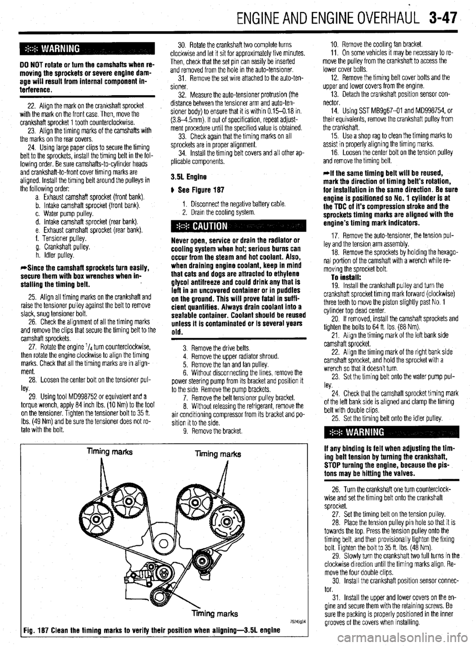
Timing marks
liming marks
Tinning marks
79245934 Fig. 187 Clean the timing marks to verify their position when aligning-3.51 engine
10. Remove the cooling fan bracket.
11, On some vehicles It may be necessary to re-
move the pulley from the crankshaft to access the
lower cover bolts.
12. Remove the timing belt cover bolts and the
upper and lower covers from the engme.
13. Detach the crankshaft position sensor con-
nector
14. Using SST MB9g67-01 and MD998754, or
their equivalents, remove the crankshaft pulley from
the crankshaft.
15. Use a shop rag to clean the timing marks to
assist in properly aligning the timing marks.
16. Loosen the center bolt on the tension pulley
and remove the timing belt.
@if the same timing belt will be reused,
mark the direction of timing belt’s rotation,
for installation in the same direction. Be sure
engine is positioned so No. 1 cylinder is at
the TDC of it’s compression stroke and the
sprockets timing marks are aligned with the
engine’s timing mark indicators.
17. Remove the auto-tensioner, the tension pul-
ley and the tension arm assembly.
18. Remove the sprockets by holding the hexago-
nal portion of the camshaft with a wrench while re-
moving the sprocket bolt.
To install: 19. Install the crankshaft pulley and turn the
crankshaft sprocket timing mark forward (clockwise)
three teeth to move the piston slightly past No. 1
cylinder top dead center.
20. If removed, install the camshaft sprockets and
tighten the bolts to 64 ft. Ibs. (88 Nm).
21, Align the timing mark of the left bank side
camshaft sprocket.
22. Align the timing mark of the right bank side
camshaft sprocket, and hold the sprocket with a
wrench so that it doesn’t turn.
23. Set the timing belt onto the water pump pul-
ley.
24. Check that the camshaft sprocket timing mark
of the left bank side is aligned and clamp the timing
belt with double clips.
25. Set the timing belt onto the idler pulley.
if any binding is felt when adjusting the tim-
ing belt tension by turning the crankshaft,
STOP turning the engine, because the pis-
tons may be hitting the valves.
26. Turn the crankshaft one turn counterclock-
wise and set the timing belt onto the crankshaft
sprocket.
27. Set the timing belt on the tension pulley.
28. Place the tension pulley pin hole so that it is
towards the top. Press the tension pulley onto the
timing belt, and then provisionally tighten the fixing
bolt. Tighten the bolt to 35 ft. Ibs. (48 Nm).
29. Slowly turn the crankshaft two full turns in the
clockwise direction until the timing marks align. Re-
move the four double clips.
30. Install the crankshaft position sensor connec-
tor.
31. Install the upper and lower covers on the en-
gine and secure them with the retaining screws. Be
sure the packing is properly positioned in the inner
grooves of the covers when installing.
Page 208 of 408
CHASSIS ELECTRiCAL 6-5
them. It is used for voltage and ground tests. To use voltmeter has a positive and a negative lead. To avoid
a 12 volt test light, connect the ground clip to a good damage to the meter, always connect the negative
ground and probe wherever necessary with the pick. lead to the negative (-) side of the circuit (to ground
The test light will illuminate when voltage is detected. or nearest the ground side of the circuit) and connect
This
does not necessarily mean that 12 volts (or any the positive lead to the positive(t) side of the circuit When diagnosing a specific problem, organized
troubleshooting is a must. The complexity of a mod-
particular amount of voltage) is present; it only (to the power source or the nearest power source).
means that some voltage is present. It is advisable Note that the negative voltmeter lead will always be ern automotive vehicle demands that you approach
before using the test light to touch its ground clip black and that the positive voltmeter will always be any problem in a logical, organized manner. There
and probe across the battery posts or terminals to some color other than black (usually red). are certain troubleshooting techniques, however,
which are standard:
make sure the light is operating properly.
l Ohmmeter-the ohmmeter is designed to read l Establish when the problem occurs. Does the
resistance (measured in ohms) in a circuit or compo-
nent. Most ohmmeters will have a selector switch problem appear only under certain conditions? Were
there any noises, odors or other unusual symptoms?
Do not use a test light to probe electronic ig- which permits the measurement of different ranges of
Isolate the problem area. To do this, make some sim-
nition, spark plug or coil wires. Never use a resistance (usually the selector switch allows the
multiplication of the meter reading by 10,100,1,000 ple tests and observations, then eliminate the sys-
pick-type test light to probe wiring on com- terns that are working properly. Check for obvious
puter controlled systems unless specifically and 10,000). Some ohmmeters are “auto-ranging”
which means the meter itself will determine which problems, such as broken wires and loose or dirty
instructed to do so. Any wire insulation that
scale to use. Since the meters are powered by an in- connections. Always check the obvious before as-
is pierced by the test light probe should be
ternal battery, the ohmmeter can be used like a self- suming something complicated is the cause.
taped and sealed with silicone after testing.
l Test for problems systematically to determine
powered test light. When the ohmmeter is connected,
the cause once the problem area is isolated. Are all
Like the jumper wire, the 12 volt test light is used current from the ohmmeter flows through the circuit
the components functioning properly? Is there power
to isolate opens in circuits. But, whereas the jumper or component being tested. Since the ohmmeter’s in-
ternal resistance and voltage are known values, the going to electrical switches and motors. Performing
wire is used to bypass the open to operate the load,
amount of current flow through the meter depends on careful, systematic checks will often turn up most
the 12 volt test light is used to locate the presence of
the resistance of the circuit or component being causes on the first inspection, without wasting time
voltage in a circuit. If the test light illuminates, there
tested. The ohmmeter can also be used to perform a checking components that have little or no relation-
is power up to that point in the circuit; if the test light ship to the problem.
does not illuminate, there is an open circuit (no continuity test for suspected open circuits. In using
the meter for making continuity checks, do not be
l Test all repairs after the work is done to make
power). Move the test light in successive steps back
concerned with the
actual resistance readings. Zero sure that the problem is fixed. Some causes can be
toward the power source until the light in the handle traced to more than one component, so a careful veri-
illuminates. The open is between the probe and a resistance, or any ohm reading, indicates continuity
fication of repair work is important in order to pick up
point which was previously probed. in the circuit, Infinite resistance indicates an opening
in the circuit. A high resistance reading where there additional malfunctions that may cause a problem to
The self-powered test light is similar in design to
should be none indicates a problem in the circuit. reappear or a different problem to arise. A blown
the 12 volt test light, but contains a 1.5 volt penlight
Checks for short circuits are made in the same man- fuse, for example, is a simple problem that may re-
battery in the handle. It is most often used in place of
ner as checks for open circuits, except that the circuit quire more than another fuse to repair. If you don’t
a multimeter to check for open or short circuits when look for a problem that caused a fuse to blow, a
power is isolated from the circuit (continuity test). must be isolated from both power and normal
ground. Infinite resistance indicates no continuity, shorted wire (for example) may go undetected.
The battery in a self-powered test light does not Experience has shown that most problems tend
provide much current. A weak battery may not pro- while zero resistance indicates a dead short.
to be the result of a fairly simple and obvious
vide enough power to illuminate the test light even I ’ cause, such as loose or corroded connectors, bad
when a complete circuit is made (especially if there is grounds or damaged wire insulation which causes a
high resistance in the circuit). Always make sure that Never use an ohmmeter to check the resis- short. This makes careful visual inspection of com-
the test battery is strong. To check the battery, briefly tance of a component or wire while there is ponents during testing essential to quick and accu-
touch the ground clip to the probe; if the light glows voltage applied to the circuit. rate troubleshooting.
brightly, the battery is strong enough for testing.
*A self-powered test light should not be
l Ammeter-an ammeter measures the amount
- I
used on any computer controlled system or of current flowing through a circuit in units called
component. The small amount of electricity amperes or amps. At normal operating voltage, most
circuits have a characteristic amount of amperes, OPEN CIRCUITS
transmitted by the test light is enough to
damage many electronic automotive compo- called “current draw” which can be measured using
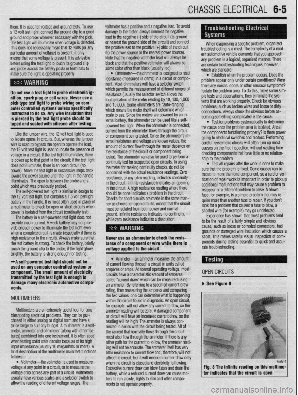
an ammeter. By referring to a specified current draw # See Figure 8
nents.
rating, then measuring the amperes and comparing
MULTIMETERS the two values, one can determine what is happening
within the circuit to aid in diagnosis. An open circuit,
for example, will not allow any current to flow, so the
Multimeters are an extremely useful tool for trou-
bleshooting electrical problems. They can be pur- ammeter reading will be zero. A damaged component
or circuit will have an increased current draw, so the
chased in either analog or digital form and have a
reading will be high. The ammeter is always con-
price range to suit any budget. A multimeter is a volt-
netted in series with the circuit being tested. All of
meter, ammeter and ohmmeter (along with other fea-
the current that normally flows through the circuit
tures) combined into one instrument. It is often used
must also flow through the ammeter; if there is any
when testing solid state circuits because of its high
other path for the current to follow, the ammeter read-
input impedance (usually 10 megaohms or more). A
ing will not be accurate. The ammeter itself has very
brief description of the multiieter main test functions
follows: little resistance to current flow and, therefore, will not
affect the circuit, but it will measure current draw only
l Voltmeter--the voltmeter is used to measure
when the circuit is closed and electricity is flowing.
voltage at any point in a circuit, or to measure the
Excessive current draw can blow fuses and drain the
voltage drop across any part of a circuit. Voltmeters
battery, while a reduced current draw can cause mo-
usually have various scales and a selector switch to
tors to run slowly, lights to dim and other compo-
allow the reading of different voltage ranges. The
nents to not operate properly.
Page 230 of 408
CHASSIS ELECTRICAL 6-27
1. Remove the fuse box cover.
2. lnsoect the fuses to determine which is faulty.
REPLACEMENT 3. Grasp the fuse and remove it from the fuse
box. Never exceed the amperage rating of a blown
4. Inspect the box terminals and clean if cor- fuse. If the replacement fuse also blows,
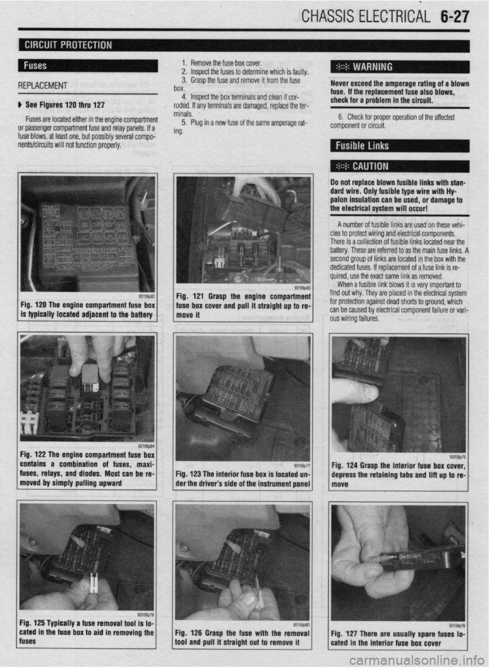
It See Figures 120 thru 127 check for a problem in the circuit.
roded. If any terminals are damaged, replace the ter-
Fuses are located either in the engine Compartment minals. ’
5. Plug in a new fuse of the same amperage rat- 6. Check for proper operation of the affected
or passenger compartment fuse and relay panels. If a component or circuit.
fuse blows, at least one, but possibly several compo- ing.
ients/circuits will not function properly.
Fig, 120 The engine compartment fuse box
is typically located adjacent to the
battery
Fig. 122 The engine compartment fuse box
contains a combination of fuses, maxi-
fuses, relays, and diodes. Most can be re-
moved by simply pulling upward
I Do not replace blown fusible links with stan-
dard wire. Only fusible type wire with Hy
palon insulation can be
used, or damage to
the electrical system will occur!
A number of fusible links are used on these vehi-
cles to protect wiring and electrical components.
There is a collection of fusible links located near the
battery. These are referred to as the main fuse links. A
second group of links are located in the box with the
dedicated fuses. If replacement of a fuse link is re-
quired, use the exact same link as removed.
When a fusible link blows it is very important to
Fig. 121 Grasp the engine compartment find out why. They are placed in the electrical system
. ’ ‘“‘,+“” 1 ous wiring failures. fuse box cover and pull It straight up to re- for protection against dead shorts to ground, which
move it can be caused by electrical component failure or vari-
Fig. 123 The interior fuse box is located un-
der the driver’s side of the instrument panel
Fig. 125 Typically a fuse removal tool is lo-
cated in the fuse box to aid in removing the
fuses Fig. 126 Grasp the fuse with the removal
tool and pull it straight out to remove it Fig. 124 Grasp the interior fuse box cover,
depress the retaining
tabs and lift up to re-
Page 384 of 408
11-2 TROUBLESHOOTING
Condition
Section/Item Number
The following troubleshooting charts are divided into 7 sections covering engine, drive train, brakes, wheels/tires/steering/suspension, electrical accessories, instruments and gauges,
and climate control. The first portion (or index) consists of a list of symptoms, along with section and item numbers. After selecting the appropriate condition, refer to the corresponding
diagnostic procedure in the second portion’s specified location.
INDEX
Gasoline Engines Engine turns over, but will not start
Engine does not turn over when attempting to start
Engine stalls immediately when started
Starter motor spins, but does not engage
Engine is difficult to start when cold
Engine is difficult to start when hot
Diesel Engines Engine turns over but won’t start
Engine does not turn over when attempting to start
Engine stalls after starting
Starter motor spins, but does not engage
Engine is difficult to start I-A, 1
l-A, 2
I-A, 3
I-A, 4
I-A, 5
I-A, 6
I-A, 1
l-A, 2
I-A, 3
I-A, 4
l-A, 5
Gasoline Engines Engine runs poorly, hesitates
Engine lacks power
Engine has poorfuel economy
Engine runs on (diesels) when turned off
Engine knocks and pings during heavy acceleration, and on steep hills
Engine accelerates but vehicle does not gain speed
Diesel Engines Engine runs poorly
Engine lacks power l-B, 1
I-B, 2
l-B, 3
I-B, 4
l-B, 5
I-B, 6
l-B,-1
l-B, 2
Engine makes a knocking or pinging noise when accelerating
Starter motor grinds when used
Engine makes a screeching noise
Engine makes a growling noise
Engine makes a ticking or tapping noise
Engine makes a heavy knocking noise
Vehicle has a fuel odor when driven
Vehicle has a rotten egg odor when driven
Vehicle has a sweet odor when driven
Engine vibrates when idling
Engine vibrates during acceleration
Battery goes dead while driving
Battery goes dead overnight
Engine overheats
Engine loses coolant
Engine temperature remains cold when driving
Engine runs hot
Exhaust rattles at idle speed
Exhaust system vibrates when driving
Exhaust system seems too low
Exhaust seems loud l-C, 1
l-C, 2
l-C, 3
I-C, 4
l-C, 5
I-C, 6
l-C, 7
l-C, 8
I-C, 9
I-C, 10
l-C, 11
l-C, 1
I-C, 2
I-D, 1
I-D, 2
I-D, 3
I-D, 4
l-F, 1
l-F, 2
I-F, 3
I-F, 4
Page 390 of 408
11-8 TROUBLESHOOTING
Ignition systems may be controlled by, or linked to, the engine fuel management sys-
tem. Similar to the fuel injection system, these ignition systems rely on electronic sen-
sors for information to determine the optimum ignition timing for a given engine speed
and load. Some ignition systems no longer allow the ignition timing to be adjusted.
Feedback from low voltage electrical sensors provide information to the control unit to
determine the amount of ignition advance. On these systems, if a failure occurs the failed
component must be replaced. Before replacing suspected failed electrical components,
carefully inspect the wiring and electrical connectors to the related components. Make
sure the electrical connectors are fully connected, clean and not physically damaged. If
necessary, clean the electrical contacts using electrical contact cleaner. The use of clean-
ing agents not specifically designed for electrical contacts should be avoided, as they
could leave a surface film or damage the insulation of the wiring.
1. Engine makes a knocking or pinging noise when accelerating
a. Check the octane rating of the fuel being used. Depending on the type of driving or
driving conditions, it may be necessary to use a higher octane fuel.
b. Verify the ignition system settings and operation. Improperly adjusted ignition timing
or a failed component, such as a knock sensor, may cause the ignition timing to ad-
vance excessively or prematurely. Check the ignition system operation and adjust, or
replace components as needed.
c. Check the spark plug gap, heat range and condition. If the vehicle is operated in se-
vere operating conditions or at continuous high speeds, use a colder heat range spark
plug. Adjust the spark plug gap to the manufacturer’s recommended specification and
replace worn or damaged spark plugs.
2. Sfarter motor grinds when used
a. Examine the starter pinion gear and the engine ring gear for damage, and replace dam-
aged parts.
b. Check the starter mounting bolts and housing. If the housing is cracked or damaged
replace the starter motor and check the mounting bolts for tightness.
3. Engine makes a screeching noise
a. Check the accessory drive belts for looseness and adjust as necessary.
b. Check the accessory drive belt tensioners for seizing or excessive bearing noises and
replace if loose, binding, or excessively noisy.
c. Check for a seizing water pump. The pump may not be leaking; however, the bearing
may be faulty or the impeller loose and jammed. Replace the water pump.
4. Engine makes a growling noise
a. Check for a loose or failing water pump. Replace the pump and engine coolant.
b. Check the accessory drive belt tensioners for excessive bearing noises and replace if
loose or excessively noisy.
5. Engine makes a ticking or tapping noise
a. On vehicles with hydraulic lash adjusters, check for low or dirty engine oil and top off
or replace the engine oil and filter.
b. On vehicles with hydraulic lash adjusters, check for collapsed lifters and replace failed
components.
c. On vehicles with hydraulic lash adjusters, check for low oil pressure caused by a re-
stricted oil filter, worn engine oil pump, or oil pressure relief valve.
d. On vehicles with manually adjusted valves, check for excessive valve clearance or
worn valve train parts. Adjust the valves to specification or replace worn and defective
parts.
e. Check for a loose or improperly tensioned timing belt or timing chain and adjust or re-
place parts as necessary.
f. Check for a bent or sticking exhaust or intake valve. Remove the engine cylinder head
to access and replace.
6. Engine makes a heavy knocking noise
a. Check for a loose crankshaft pulley or flywheel; replace and torque the mounting
bolt(s) to specification.
b. Check for a bent connecting rod caused by a hydro-lock condition. Engine disassem-
bly is necessary to inspect for damaged and needed replacement parts.
c. Check for excessive engine rod bearing wear or damage. This condition is also asso-
ciated with low engine oil pressure and will require engine disassembly to inspect for
damaged and needed replacement parts,
7. Vehicle has a fuel odor when driven ’ a. Check the fuel gauge level. If the fuel gauge registers full, it is possible that the odor is
caused by being filled beyond capacity, or some spillage occurred during refueling.
The odor should clear after driving an hour, or twenty miles, allowing the vapor canis-
ter to purge.
b. Check the fuel filler cap for looseness or seepage. Check the cap tightness and, if
loose, properly secure. If seepage is noted, replace the filler cap.
c. Check for loose hose clamps, cracked or damaged fuel delivery and return lines, or
leaking components or seals, and replace or repair as necessary. d. Check the vehicle’s fuel economy. If fuel consumption has increased due to a failed
component, or if the fuel is not properly ignited due to an ignition related failure, the
catalytic converter may become contaminated. This condition may also trigger the
check engine warning light. Check the spark plugs for a dark, rich condition or verify
the condition by testing the vehicle’s emissions. Replace fuel fouled spark plugs, and
test and replace failed components as necessary.
5. Vehicle has a rotten egg odor when driven
a. Check for a leaking intake gasket or vacuum leak causing a lean running condition. A
lean mixture may result in increased exhaust temperatures, causing the catalytic con-
verter to run hotter than normal. This condition may also trigger the check engine
warning light. Check and repair the vacuum leaks as necessary.
b. Check the vehicle’s alternator and battery condition. If the alternator is overcharging,
the battery electrolyte can be boiled from the battery, and the battery casing may begin
to crack, swell or bulge, damaging or shorting the battery internally. If this has oc-
curred, neutralize the battery mounting area with a suitable baking soda and water
mixture or equivalent, and replace the alternator or voltage regulator. Inspect, service,
and load test the battery, and replace if necessary.
9. Vehicle has a sweet odor when driven
a. Check for an engine coolant leak caused by a seeping radiator cap, loose hose clamp,
weeping cooling system seal, gasket or cooling system hose and replace or repair as
needed.
b. Check for a coolant leak from the radiator, coolant reservoir, heater control valve or
under the dashboard from the heater core, and replace the failed part as necessary.
c. Check the engine’s exhaust for white smoke in addition to a sweet odor. The presence
of white, steamy smoke with a sweet odor indicates coolant leaking into the combus-
tion chamber. Possible causes include a failed head gasket, cracked engine block or
cylinder head. Other symptoms of this condition include a white paste build-up on the
inside of the oil filler cap, and softened, deformed or bulging radiator hoses.
19. Engine vibraies when idling
a. Check for loose, collapsed, or damaged engine or transmission mounts and repair or
replace as necessary.
b. Check for loose or damaged engine covers or shields and secure or replace as neces-
sary.
11. Engine vibrates during acceleration
a. Check for missing, loose or damaged exhaust system hangers and mounts; replace or
repair as necessary.
b. Check the exhaust system routing and fit for adequate clearance or potential rubbing;
repair or adjust as necessary.
7. Battery goes dead while driving
a. Check the battery condition. Replace the battery if the battery will not hold a charge or
fails a battery load test. If the battery loses fluid while driving, check for an overcharg-
ing condition. If the alternator is overcharging, replace the alternator or voltage regula-
tor. (A voltage regulator is typically built into the alternator, necessitating alternator re-
placement or overhaul.)
b. Check the battery cable condition. Clean or replace corroded cables and clean the bat-
tery terminals.
c. Check the alternator and voltage regulator operation. If the charging system is over or
undercharging, replace the alternator or voltage regulator, or both.
d. Inspect the wiring and wire connectors at the alternator for looseness, a missing .
ground or defective terminal, and repair as necessary.
e. Inspect the alternator drive belt tension, tensioners and condition. Properly tension the
drive belt, replace weak or broken tensioners, and replace the drive belt if worn or
cracked.
2. Battery goes dead overnight
a. Check the battery condition. Replace the battery if the battery will not hold a charge or
fails a battery load test.
b. Check for a voltage draw, such as a trunk light, interior light or glove box light staying
on. Check light switch position and operation, and replace if defective.
c. Check the alternator for an internally failed diode, and replace the alternator if defec-
tive.
1. Engine overheats
a. Check the coolant level. Set the heater temperature to full hot and check for internal air
pockets, bleed the cooling system and inspect for leakage. Top off the cooling system
with the correct coolant mixture.
b. Pressure test the cooling system and radiator cap for leaks. Check for seepage caused
by loose hose clamps, failed coolant hoses, and cooling system components such as
the heater control valve, heater core, radiator, radiator cap, and water pump. Replace
defective parts and fill the cooling system with the recommended coolant mixture.
Page 406 of 408
l
II-24 MASTER INDEX
ADJUSTMENT 8-25
REMOVAL &INSTALLATION 8-25
HYDRAULIC CONTROL UNIT 9-25
REMOVAL & INSTALLATION 9-25
IDLE AIR CONTROLMOTOR 4-9
OPERATION 4-9
REMOVAL&INSTALLATION 4-9
TESTING 4-9
IDLESPEED 1-28
PREVENTIVEMAINTENANCE 1-28
SYSTEM INSPECTION 1-29
SYSTEMSERVlCE&REPAlR 1-28
IGNITION LOCK CYLINDER 8-29
REMOVAL & INSTALLATION 8-29
IGNITION SWITCH 8-30
REMOVAL & INSTALLATION 8-30
IGNITION COIL(s) 2-5
REMOVAL&INSTALLATION 2-6
TESTING . 2-5
IGNITION COIL 2-3
REMOVAL&INSTALLATION 2-3
TESTING 2-3
IGNITION TIMING l-25
GENERALINFORAMTION l-25
INSPECTION&ADJUSTMENT l-26
INSIDE REAR VIEW MIRROR
IO-IO
REPLACEMENT IO-IO
INSPECTION 3-55
REPLACEMENT 3-56
INSTRUMENT CLUSTER 6-17
REMOVAL&INSTALLATION 6-I;
INSTRUMENTPANEL IO-6
REMOVAL &INSTALLATION IO-6
INSTRUMENTS AND SWITCHES 6-17
INTAKE MANIFOLD 3-7
REMOVAL &INSTALLATION 3-7
INTAKEAIRTEMPERATURESENSOR 4-10
OPERATION 4-10
REMOVAL&INSTALLATION 4-11
TESTING 4-11
INTERIOR 1 O-6
JACKING I-46
. JACKING PRECAUTIONS 1-47
JUMP STARTING A DEAD BATTERY 1-44
JUMPSTARTING PRECAUTIONS l-45
JUMPSTARTING PROCEDURE l-45
KNUCKLE,HUB, AND BEARING 8-13
REMOVAL &INSTALLATION 8-13
LIGHTING 6-19
LOWER BALLJOINT 8-10
INSPECTION 8-10
REMOVAL & INSTALLATION 8-10
LOWER CONTROLARM 8-10
REMOVAL&INSTALLATION 8-10
LOWER CONTROL ARMS 8-23
REMOVAL & INSTALLATION 8-23
MACPHERSONSTRUTAND COILSPRING
8-7
OVERHAUL 8-7
REMOVAL & INSTALLATION 8-7
MAINTENANCEORREPAIR? l-2
MANIFOLDABSOLUTEPRESSURESENSOR
4-12
OPERATION 4-12
REMOVAL&INSTALLATION 4-13
TESTING 4-12
MANUAL RACK AND PINION STEERING GEAR
8-31
REMOVAL & INSTALLATION 8-31
MANUALTRANSAXLEASSEMBLY 7-2
REMOVAL & INSTALLATION. 7-2
MANUAL TRANSAXLE 7-2 MANUALTRANSAXLE l-35
DRAIN &REFILL l-36
FLUID RECOMMENDATIONS l-35
LEVEL CHECK l-35
MASSAIRFLOWSENSOR 4-11
OPERATION 4-11
REMOVAL&INSTALLATION 4-11
TESTING 4-11
MASTER CYLINDER 9-3
BRAKE PEDALADJUSTMENTS 9-4
REMOVAL & INSTALLATION 9-3
MULTI-POINT FUEL INJECTION SYSTEM (MPI) 5-3
DBD-1 TROUBLE CODES 4-26
OBD-II TROUBLE CODES 4-27
OIL PAN 3-30
REMOVAL & INSTALLATION 3-30
OIL PUMP 3-33
REMOVAL & INSTALLATION 3-33
OIL PRESSURESENDING UNIT 2-12@T
REMOVAL&INSTALLATION 2-1.2
TESTING 2-12
OUTSIDE MIRRORS IO-3
REMOVAL&INSTALLATION IO-3
OXYGENSENSOR 4-8
OPERATION 4-8
REMOVAL&INSTALLATION 4-8
TESTING 4-8
PARK/NEUTRAL POSITIONSWITCH 7-10
ADJUSTMENT 7-10
REMOVAL & INSTALLATION 7-10
PARKING BRAKE 9-20
PCVVALVE l-15
REMOVAL&INSTALLATION I-15
PINION SEAL 7-16
REMOVAL &INSTALLATION 7-16
POWER BRAKEBOOSTER 9-5
REMOVAL &INSTALLATION 9-5
POWER RACK AND PINION STEERING GEAR 8-32
REMOVAL &INSTALLATION 8-32
POWERSEATMOTOR IO-11
REMOVAL & INSTALLATION IO-11
POWER STEERING PUMP 8-34
REMOVAL & INSTALLATION 8-34
SYSTEM BLEEDING 8-36
POWER TRANSlSTOR(IGNITION MODULE) 2-7
REMOVAL&INSTALLATION 2-7
POWERSTEERING PUMP l-42
FLUID RECOMMENDATIONS l-42
LEVELCHECK l-42
POWER TRANSlSTOR(Ignition Module) 2-4
REMOVAL&INSTALLATION 2-4
PRESSURERELIEFVALVE 5-9
REMOVAL&INSTALLATION 5-9
PROPORTIONING VALVE 9-6
REMOVAL & INSTALLATION 9-6 *
RADIATOR 3-18
REMOVAL &INSTALLATION 3-18
RADIO RECEIVER/AMPLIFIER/TAPE PLAYER/CD PLAYER 6-14
READING CODES 4-26
WITHASCANTOOL 4-26
WITHOUTASCANTOOL 4-27
READING CODES 4-27
WITHASCANTOOL 4-27
WITHOUTASCANTOOL 4-27
REAR AXLE DIFFERENTIAL 7-15
REAR HALFSHAFTAND SEAL 7-15
REMOVAL&INSTALLATION 7-15
REAR MAIN SEAL 3-54
REMOVAL & INSTALLATION 3-54