1900 MITSUBISHI DIAMANTE headlight aiming
[x] Cancel search: headlight aimingPage 204 of 408
UNDERSTANDING AND
TROUBLESHOOTING
ELECTRICAL SYSTEMS 6-2
BASIC ELECTRICALTHEORY 6-2
HOW DOES ELECTRICITY WORK:
THEWATERANALOGY 6-2
OHM'S LAW 6-2
ELECTRICALCOMPONENTS 6-2
POWERSOURCE 6-2
GROUND 6-3
PROTECTIVE DEVICES 6-3
SWITCHES&RELAYS 6-3
LOAD 6-3
WIRING & HARNESSES 6-3
CONNECTORS 6-4
TEST EQUIPMENT 6-4
JUMPER WIRES 6-4
TEST LIGHTS 6-4
MULTIMETERS 6-5
TROUBLESHOOTING ELECTRICAL
SYSTEMS 6-5
TESTING 6-5
OPEN CIRCUITS 6-5
SHORT CIRCUITS 6-6
VOLTAGE 6-6
VOLTAGE DROP 6-6
RESISTANCE 6-8
WIRE AND CONNECTORREPAIR 6-6
BATTERY CABLES 6-7
DISCONNECTING THE CABLES 6-7
AIR BAG (SUPPLEMENTAL
RESTRAINT SYSTEM) 6-7
GENERALINFORMATION 6-7
SERVICE PRECAUTIONS 6-7
DISARMING 6-7
REARMING 6-7
HEATING AND AIR
CONDITIONING 6-7
BLOWER MOTOR 6-7
REMOVAL &INSTALLATION 6-7
HEATER CORE 6-9 INSTRUMENTS AND SWITCHES 6-17
INSTRUMENTCLUSTER 6-17
REMOVAL &INSTALLATION 6-17
GAUGES 6-18
REMOVAL&INSTALLATION 6-18
WINDSHIELD WIPER SWITCH 6-19
REMOVAL&INSTALLATION 6-19
REARWINDOWWIPERSWITCH 6-19
REMOVAL &INSTALLATION 6-19
DIMMER SWITCH 6-19
REMOVAL & INSTALLATION 6-19 .
HEADLIGHT SWITCH 6-19
REMOVAL & INSTALLATION 6-19
LIGHTING 6-19
HEADLIGHTS 6-19
REMOVAL &INSTALLATION 6-19
AIMINGTHEHEADLIGHTS 6-20
SIGNAL AND MARKER LIGHTS 6-21
REMOVAL &INSTALLATION 6-21
CIRCUIT PROTECTION 6-27
FUSES 6-27
REPLACEMENT 6-27
FUSIBLE LINKS 6-27
CIRCUIT BREAKERS 6-28
RESETTING AND/OR
REPLACEMENT 6-28
FLASHERS 6-28
REPLACEMENT 6-28
WIRING DIAGRAMS 6-31
REMOVAL & INSTALLATION 6-9
AIR CONDITIONING COMPONENTS 6-11
REMOVAL & INSTALLATION 6-11
CONTROLCABLES 6-12
ADJUSTMENT 6-12
CONTROL PANEL 6-12
REMOVAL & INSTALLATION 6-12
CRUISE CONTROL 6-13
ENTERTAINMENT SYSTEMS 6-14
RADIO RECEIVER/AMPLIFIER/TAPE
PLAYER/CD PLAYER 6-14
SPEAKERS 6-14
REMOVAL & INSTALLATION 6-14
WINDSHIELD WIPERS AND
WASHERS 6-15
WINDSHIELD WIPER BLADE AND
ARM 6-15
REMOVAL & INSTALLATION 6-15
WINDSHIELD WIPER MOTOR 6-16 _
REMOVAL &INSTALLATION 6-16
WINDSHIELD WASHER PUMP 6-17
REMOVAL &INSTALLATION 6-17
Page 223 of 408
.
6-20 CHASSIS ELECTRICAL
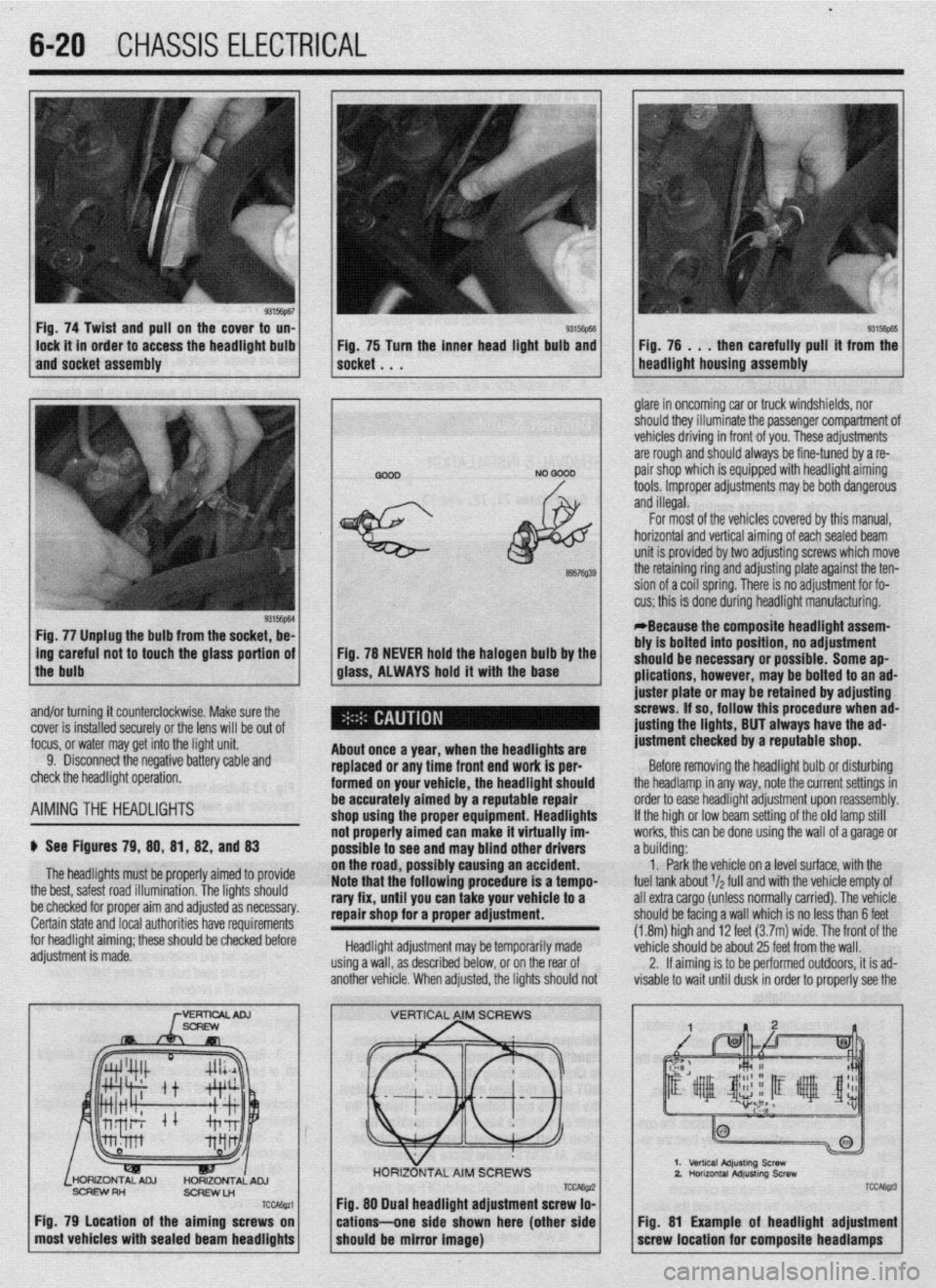
Fig. 74 Twist and pull on the cover to un-
lock it in order to access the headlight bulb
and socket assembly 93Mm Fig, 75 Turn the inner head light bulb and then carefully pull’ it from the
NO 0000 . glare in oncoming car or truck windshields, nor
should they illuminate the passenger compartment of
vehicles driving in front of you. These adjustments
are rough and should always be fine-tuned by a re-
pair shop which is equipped with headlight aiming
tools. Improper adjustments may be both dangerous
and illegal.
Fig. 77 Unplug the bulb from the socket, be-
L
ing careful not to touch the glass portion of
the bulb
I
6957Q39
Fig. 78 NEVER hold the halogen bulb by the
glass, ALWAYS hold it with the base
,
About once a year, when the headllgftts are
replaced or any time front end work is per-
formed on your vehicle, the headlight should
be accurately aimed by a reputable repair
shop uslng the proper equipment. Headlights
not properly aimed can make it virtually im-
possible to see ar Id may blind other drivers
ibly causing an accident.
Note that the’following procedure is a tempo-
rary fix, until you can take your vehicle to a
repair shop for a proper adjustment.
Headlight adjustment may be temporarily made
using a wall, as described below, or on the rear of
another vehicle. When adjusted, the lights should not For most of the vehicles covered by this manual,
horizontal and vertical aiming of eachsealed beam
unit is provided by two adjusting screws which move
the retaining ring and adjusting plate against the ten-
sion of a coil spring. There is no adjustment for fo-
cus; this is done during headlight manufacturing.
*Because the composite headlight assem-
bly is bolted into position, no adjustment
should be necessary or possible. Some ap-
plications, however, may be bolted to an ad-
juster plate or may be retained by adjusting
screws. If so, follow this procedure when ad-
@sting the lights, BUT always have the ad-
justment checked by a reputable shop.
Before removing the headlight bulb or disturbing
the headlamp in any way, note the current settings in
order to ease headlight adjustment upon reassembly.
If the high or low beam setting of the old lamp still
works, this can be done using the wall of a garage or
a building:
1. Park the vehicle on a level surface, with the
fuel tank about r/a full and with the vehicle empty of
all extra cargo (unless normally carried). The vehicle
should be facing a wall which is no less than 6 feet
(1.8m) high and 12 feet (3.7m) wide. The front of the
vehicle should be about 25 feet from the wall.
2. If aiming is to be performed outdoors, it is ad-
visable to wait until dusk in order to properly see the
% and/or turning it counterclockwise. Make sure the
cover is installed securely or the lens will be out of
focus, or water may get into the light unit.
9. Disconnect the negative battery cable and
check the headlight operation.
AIMINGTHE HEADLIGHTS
$ See Figures 79, 88, 81, 82, and 83
The headlights must be proper’ ’ ’ ’
the best, safest road illumination. ’ ’
ly armea IO provrae
The lights should
:.__1__1 __ - -___-_-. on the road, POSSI
be checked for proper aim and adfusreu as IlweSYdly. Certain state and local authorities have requirements
for headlight aiming; these should be checked before
adjustment is made.
SCFEWRH
ScFlEwLn
TCcAssa
Fig. 79 Location of the aiming screws on
most vehicles with sealed beam headlights
TCCAE@ Fig. 88 Dual headlight adjustment screw lo-
cations--one side shown here (other side
should be mirror image)
2.
TCC&z3
Fig. 81 Example of headlight adjustment
screw location for composite headlamps
Page 405 of 408
MASTER INDEX 11-23
GENERALINFORMAITON 3-65
INSPECTION 3-65
REFINISHING 3-67
ENGINE FAN 3-19
REMOVAL & INSTALLATION 3-19
ENGINE MECHANICAL 3-1
ENGINE OVERHAUL TIPS 3-58
CLEANING 3-58
OVERHAUL TIPS 3-58
REPAIRING DAMAGEDTHREADS 3-59
TOOLS 3-58
ENGINE PREPARATION 3-59
ASSEMBLY 3-64
DISASSEMBLY 3-60
INSPECTION 3-
REFINISHING & REPAIRING 3-63
ENGINE RECONDITIONING 3-57
ENGINE START-UP AND BREAK-IN
3-69
BREAKING IT IN 3-69
KEEP IT MAINTAINED 3-69
STARTING THE ENGINE 3-69
ENGINE 'l-33
OIL& FILTER CHANGE 1-34
OILLEVELCHECK 1-33
ENGINE 3-1
REMOVAL&INSTALLATION 3-l
ENGlNECONTROLUNIT/POWERTRAINCONTROLMODULE(ECU/PCM)
4-7
OPERATION 4-7
REMOVAL&INSTALLATION 4-7
ENGINECOOLANTTEMPERATURESENSOR
4-10
OPERATION 4-10
REMOVAL&INSTALLATION 4-10
TESTING 4-10
ENGINECOOLANTTEMPERATURESENDING
UNIT 2-11
REMOVAL&INSTALLATION 2-11
TESTING 2-11
ENGINE IDENTIFICATION NUMBER l-10
ENTERTAINMENT SYSTEMS 6-14
EVAPORATIVECANISTER I-16
SERVICING 1-16
' EVAPORATIVEEMISSIONCONTROLS 4-2
COMPONENTTESTING 4-3
OPERATION 4-2
REMOVAL&INSTALLATION 4-4
EXHAUST MANIFOLD 3-14
REMOVAL & INSTALLATION 3-14
EXHAUST SYSTEM 3-55
EXHAUSTGASRECIRCULATION SYSTEM
4-5
COMPONENTTESTING 4-5
OPERATION 4-5
REMOVAL&INSTALLATION 4-6
EXTERIOR 1 O-2
FASTENERS, MEASUREMENTS AND CONVERSIONS 1-6
. FENDERS 10-4
REMOVAL &INSTALLATION IO-4
FIRING ORDERS 2-7
FLASHERS 6-28
REPLACEMENT 6-28
FLOOR CONSOLE IO-6
REMOVAL& INSTALLATION IO-6 1
FLUID PAN 7-10
FLUID DISPOSAL 1-33
FLUIDS AND LUBRICANTS 1-33
FLYWHEEVDRIVEPLATE 3-55
REMOVAL & INSTALLATION 3-55
FRONT CRANKSHAFT SEAL 3-48
REMOVAL & INSTALLATION 3-48
FRONT SUSPENSION 8-4 FRONTWHEELDRIVEMODELS 1-44
FUELANDENGINEOILRECOMMENDATIONS 1-33
ENGINEOIL l-33
FUEL 1-33
OPERATION IN FOREIGN COUNTRIES
1-33
FUEL LINE FITTINGS 5-2
REMOVAL&INSTALLATION 5-2
FUEL RAIL AND INJECTORS(S)
5-4
REMOVAL &INSTALLATION 5-4
TESTING 5-8
FUELSYSTEM SERVICE PRECAUTIONS 5-3
FUELFILTER 1-15
REMOVAL&INSTALLATION l-15
FUEL LINES AND FITTINGS 5-2
FUELPRESSUREREGULATOR 5-9
REMOVAL & INSTALLATION 5-9
FUEL TANK 5-10
FUSES 6-27
REPLACEMENT 6-27
FUSIBLE LINKS 6-27 #
RESETTING AND/OR REPLACEMENT 6-28
GAUGES 6-18
REMOVAL & INSTALLATION 6-18
GENERAL INFORMATION 5-3
GENERAL INFORMATION 6-7
DISARMING 6-7
REARMING 6-7
SERVICE PRECAUTIONS 6-7
GENERAL INFORMATION 9-24
PRECAUTIONS 9-24
GENERALINFORMATION 2-10
GENERALINFORMATION 2-2
CYLINDER DROPTEST 2-2
SECONDARYSPARKTEST 2-2
GENERALINFORMATION 2-5
GENERALINFORMATION 2-8
REMOVAL &INSTALLATION 2-9'
TESTING 2-8
GENERALINFORMATION 4-26
CHECKENGlNE/MALFUNCTlONlNDlCATOR LIGHT 4-26
SERVICE PRECAUTIONS 4-26
GENERALINFORMATION 4-27
G-SENSOR 9-29
REMOVAL &INSTALLATION 9-29
HALFSHAFTS 7-13
HALFSHAFTS 7-3
CV-JOINTS OVERHAUL 7-5
REMOVAL&INSTALLATION 7-3
HATCH/TAILGATE/TRUNKLID LOCKCYLINDER lo-10
REMOVAL & INSTALLATION IO-IO
HATCH IO-3
ALIGNMENT IO-3
REMOVAL & INSTALLATION IO-3
HEADLIGHT SWITCH 6-19
REMOVAL 81 INSTALLATION 6-19
HEADLIGHTS 6-19
AIMING THE HEADLIGHTS 6-20
REMOVAL& INSTALLATION 6-19
HEATER CORE 6-9
REMOVAL&INSTALLATION 6-9
HEATING AND AIR CONDITIONING 6-7
HOOD IO-2
ALIGNMENT IO-3
REMOVAL & INSTALLATION IO-2
HOSES I-20
INSPECTION I-20
REMOVAL&INSTALLATION I-21
HOW TO USE THIS BOOK 1-2
HUB & BEARINGS 8-25