1900 MITSUBISHI DIAMANTE air filter
[x] Cancel search: air filterPage 1 of 408
HOW TO USE THIS BOOK 1-2
WHERE TOBEGIN l-2
AVOIDINGTROUBLE 1-2
MAINTENANCEORREPAIR? 1-2
AVOIDINGTHEMOSTCOMMONMISTAKES l-2
TOOLS AND EQUIPMENT 1-2
SPECIALTOOLS l-4
YOUR VEHICLE SAFELY 1-4
DON'TS l-6
FASTENERS, MEASUREMENTS AND
CONVERSIONS l-6
BOLTS,NUTSANDOTHERTHREADED
RETAINERS 1-6
TORQUE l-7
TORQUEWRENCHES l-7
TORQUEANGLEMETERS 1-9
STANDARDANDMETRIC MEASUREMENTS l-9
SERIAL NUMBER IDENTIFICATION l-10
VEHICLE IDENTIFICATION NUMBER l-10
ENGINE IDENTIFICATION NUMBER I-10
TRANSAXLEIDENTIFICATION I-10
DRlVEAXLE(AWDGALANTONLY) l-10
TRANSFERCASE(AWDGALANTONLY) l-10
ROUTINE MAINTENANCE AND TUNE-UP l-14
AIRCLEANER(ELEMENT) 1-14
REMOVAL&INSTALLATION 1-14
FUELFILTER 1-15
REMOVAL &INSTALLATION l-15
PCVVALVE l-15
REMOVAL&INSTALLATION l-15
EVAPORATIVECANISTER l-16
SERVICING 1-16
BATTERY 1-16
PRECAUTIONS I-16
GENERALMAINTENANCE 1-16
BEL BATTERYFLUID 1-16
CABLES I-17
CHARGING I-18
REPLACEMENT 1-18
TS 1-18
INSPECTiON l-18
ADJUSTMENT 1-18
REMOVAL&INSTALLATION 1-18
TIMINGBELTS l-20
INSPECTION l-20
HOSES I-20
INSPECTION l-20
REMOVAL&INSTALLATION
CV-BOOTS 1-21
INSPECTION l-21
SPARKPLUGS l-22
SPARKPLUGHEATRANGE
REMOVAL&INSTALLATION
INSPECTION &GAPPING 1.
SPARKPLUG WIRES 1-24
TESTING 1-24
REMOVAL&INSTALLATION
DISTRIBUTORCAPANDROTOR
REMOVAL&INSTALLATION
INSPECTION 1-25
IGNITIONTIMING 1-25
. GENERALINFORAMTION l-
lNSPECTlON&ADJUSTMENl
VALVE LASH l-27
ADJUSTMENT l-27
IDLESPEED 1-28 1-21
l-22
l-22
-23
1-24
l-25
l-25
.25
1-26
AIR CONDITIONING SYSTEM 1-28
SYSTEMSERVlCEiiREPAlR l-28
PREVENTIVEMAINTENANCE 1-28
SYSTEM INSPECTION l-29
WINDSHIELD WIPERS l-29
ELEMENT(REFILL)CARE&
REPLACEMENT l-29
TIRESANDWHEELS l-30
TIRE ROTATION I-30
TIRE DESIGN 1-31
TIRESTORAGE l-31
INFLATION &INSPECTION l-31
CARE OFSPECIALWHEELS l-32 OPERATION INFOREIGNCOUNTRIES l-33
ENGINE l-33
OILLEVELCHECK 1-33
OIL& FILTER CHANGE l-34
MANUALTRANSAXLE l-35
FLUIDRECOMMENDATIONS l-35
LEVELCHECK l-35
DRAIN&REFILL l-36
AUTOMATICTRANSAXLE l-36
FLUIDRECOMMENDATIONS l-36
LEVELCHECK 1-36
DRAIN&REFILL l-36
PAN & FILTERSERVICE 1-36
TRANSFERCASE(AWDGAlANT ONLY) l-38
FLUIDRECOMMENDATIONS l-38
LEVELCHECK l-38
DRAIN&REFILL l-38
REARDRlVEAXLE(AWDGALANTONLY) l-38
FLUIDRECOMMENDATIONS l-38
LEVELCHECK l-38
DRAIN&REFILL l-38
COOLINGSYSTEM l-39
FLUIDRECOMMENDATIONS l-39
iM-41
FLUIDS AND LUBRICANTS 1-33
FLUID DISPOSAL 1-33
FlJELANDENGlNEOILRECOMMENDATlONS
ENGINE OIL l-33
FUEL l-33
Page 10 of 408
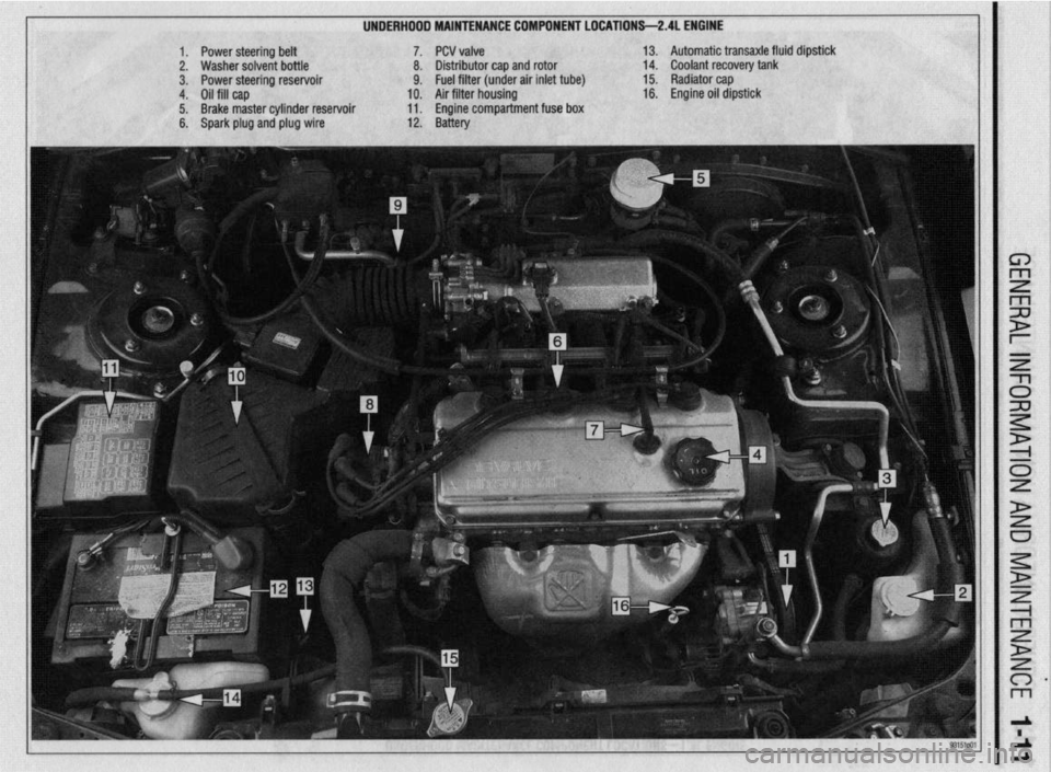
UNDERHDDD MAINTENANCE COMPONENT LOCATIONS-2AL ENGINE
II
1. Power steering belt 7. PCV valve
2. Washer solvent bottle 8. Distributor cap and rotor
3. Power steering reservoir 9. Fuel filter (under air inlet tube)
4. Oil fill cap 10. Air filter housing
5. Brake master cylinder reservoir 11. Engine compartment fuse box
6. Spark plug and plug wire 12. Battery 13. Automatic transaxle fluid dipstick
14. Coolant recovery tank
15. Radiator cap
16. Engine oil dipstick
Page 11 of 408
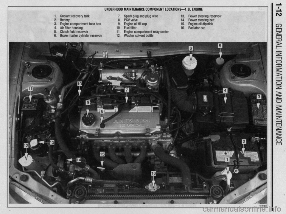
UNDERHOOD MAINTENANCE COMPONENT LOCATIONS-l .8L ENGINE
1. Coolant recovery tank
2. Battery
3. Engine compartment fuse box
4. Air filter housing
5. Clutch fluid reservoir
6. Brake master cylinder reservoir 7. Spark plug and plug wire
8. PCV valve
9. Engine oil fill cap
10. Fuel filter
11. Engine compartment relay center
12. Washer solvent bottle 13. Power steering reservoir
14. Power steering belt
15. Engine oil dipstick
16. Radiator cap
Page 13 of 408
l
l-14 GENERALINFORMATIONAND MAINTENANCE
Proper maintenance and tune-up is the key to long
and trouble-free vehicle life, and the work can yield
its own rewards. Studies have shown that a properly
tuned and maintained vehicle can achieve better gas
mileage than an out-of-tune vehicle. As a conscien-
tious owner and driver, set aside a Saturday morning,
say once a month, to check or replace items which
could cause major problems later. Keep your own
personal log to jot down which services you per-
formed, how much the parts cost you, the date, and
the exact odometer reading at the time. Keep all re-
selfer, these receipts are the only proof you have that ceipts for such items as engine oil and filters, so that
they may be referred tp in case of related problems or
to determine operating expenses. As a do-it-your- the required maintenance was performed. In the event
of a warranty problem, these receipts will be invalu-
able.
The literature provided with your vehicle when it
was originally delivered includes the factory recom-
mended maintenance schedule. If you no longer have
this literature, replacement copies are usually avail-
able from the dealer. A maintenance schedule is pro-
vided later in this section, in case you do not have
the factory literature. *
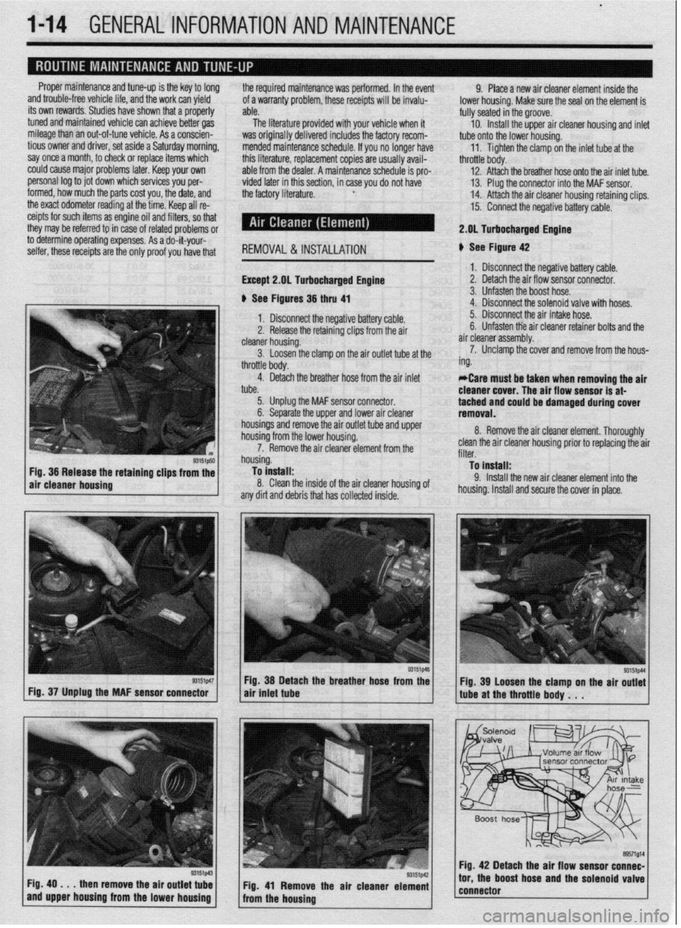
REMOVAL &INSTALLATION
Except 2.gL Turbocharged Engine
b See Figures 36 thru 41 9. Place a new air cleaner element inside the
lower housing. Make sure the seal on the element is
fully seated in the groove.
10. Install the upper air cleaner housing and inlet
tube onto the lower housing.
11. Tighten the clamp on the inlet tube at the
throttle body.
12. Attach the breather hose onto the air inlet tube.
13. Plug the connector into the MAF sensor.
14. Attach the air cleaner housing retaining clips.
15. Connect the negative battery cable.
2.DL Turbocharged Engine
b See Figure 42
1. Disconnect the negative battery cable.
2. Detach the air flow sensor connector.
3. Unfasten the boost hose.
4. Disconnect the solenoid valve with hoses.
93151p50 Fig. 36 Release the retaining clips from the
air cleaner housing
r3151p47 Fig. 37 Unplug the MAF sensor connector
Fig. 49
. . . then remove the air outlet tube
and upper housing from the lower housing 1. Disconnect the negative battery cable. 5. Disconnect the air intake hose.
2. Release the retaining clips from the air 6. Unfasten tie air cleaner retainer bolts and the
cleaner housing. air cleaner assembly.
3. Loosen the clamp on the air outlet tube at the 7. Unclamp the cover and remove from the hous-
throttle body. ing.
4. Detach the breather hose from the air inlet
tube. *Care must be taken when removing the air
cleaner cover. The air flow sensor is at-
5. Unplug the MAF sensor connector.
6. Separate the upper and lower air cleaner tached and could be damaged during cover
removal.
housings and remove the air outlet tube and upper
housing from the lower housing.
7. Remove the air cleaner element from the
housing.
To install:
8. Clean the inside of the air cleaner housing of
any dirt and debris that has collected inside. 8. Remove the air cleaner element. Thoroughly
clean the air cleaner housing prior to replacing the air
filter.
To install:
9. Install the new air cleaner element into the
housing. Install and secure the cover in place.
Fig. 38 Detach the breather hose from the
air tniet tube
Fig. 41 Remove the air cleaner element
from the housing Fig. 39 Loosen the clamp on the air outlet
tube at the throttle body . . .
Fig. 42 Detach the air flow sensor connec-
tor, the boost hose and the solenoid valve
connector
Page 14 of 408
GENERALINFORMATIONAND MAINTENANCE l-15
10. install the air cleaner assembly and the re- *Wrap shop towels around the fitting that is
tainer bolts. being dtsconnected to absorb residual fuel in
11. Connect the air intake hose. the lines. 9. While holding the fuel filter nut with aback-
up wrench, tighten the banjo bolt to 22 ft. Ibs. (30
Nm). Tighten the flare nut to 25 ft. Ibs. (35 Nm), with
12. Attach the solenoid valve.
4. Cover the hose connection with shop towels to a back-up wrench on the nut.
13. Connect the boost hose.
14. Attach the air flow sensor connector. prevent any splash of fuel that could be caused by 10. Tighten the filter mounting bolts to 10 ft. Ibs.
residual pressure in the fuel pipe line. Hold the fuel (14 Nm).
15. Connect the negative battery cable. 11.
filter nut securely with a backup wrench, then remove Connect the negative battery cable. Turn the
REMOVAL &INSTALLATION the banjo bolt on the engine feed line. Disconnect the
high-pressure fuel line from the filter. Remove and
discard the gaskets.
5. While holding the fuel filter nut securely with a
back-up wrench, loosen the filter feed pipe flare nut key to the ON position to pressurize the fuel system
and check for leaks.
12. If repairs of a leak are required, remember to
release the fuel pressure before opening the fuel sys-
tern.
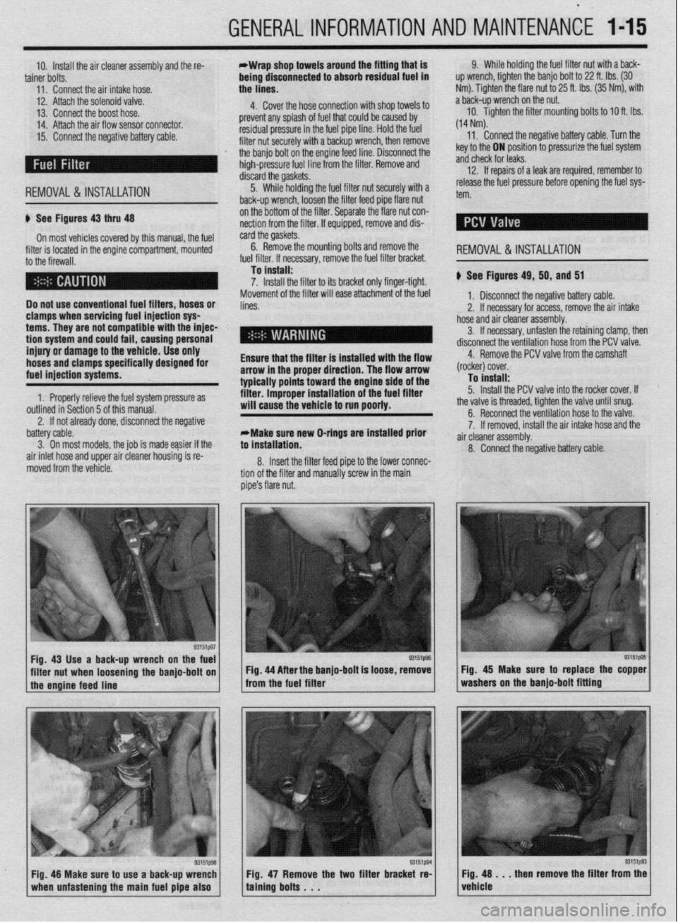
u See Figures 43 thru 48
On most vehicles covered by this manual, the fuel
filter is located in the engine compartment, mounted
to the firewall.
Do not use conventional fuel filters, hoses or
clamps when servicing fuel injection sys
terns. They are not compatible with the injec-
tion
system and could fail, causing personal
injury or damage to the vehicle. Use only
hoses and clamps specifically designed for
fuel injection systems.
1. Properly relieve the fuel system pressure as
outlined in Section 5 of this manual. on the bottom of the filter. Separate the flare nut con-
nection from the filter. If equipped, remove and dis-
card the gaskets.
6. Remove the mounting bolts and remove
. ,,,. ,.
.a r I,.,< I the
ruer rrrter. II necessary, remove me ruer rrrrer oracket.
To install:
7. Install the filter to its bracket only finger-tight.
Movement of the filter will ease attachment of the fuel
lines.
Ensure that the filter is installed with the flow
arrow in the proper direction. The flow arrow
typically points toward the engine side of the
filter. improper installation of the fuel filter
will cause the vehicle to run poorly.
2. If not already done, disconnect the negative REMOVAL&INSTALLATION
u See Figures 49, 50, and 51
1, Disconnect the negative battery cable.
2. If necessary for access, remove the air intake
hose and air cleaner assembly.
3. If necessary, unfasten the retaining clamp, then
disconnect the ventilation hose from the PCV valve.
4. Remove the PCV valve from the camshaft
(rocker) cover.
To install:
5. Install the PCV valve into the rocker cover. If
the valve is threaded, tighten the valve until snug.
battery cable.
3. On most models. the iob is made easier if the
air inlet hose and upper air cleaner housing is re-
moved from the vehicle. *Make sure new O-rings are installed prior
to installation.
8. Insert the filter feed pipe to the lower connec-
tion of the filter and manually screw in the main
pipe’s flare nut. 6. Reconnect the ventilation hose to the valve.
7. If removed, install the air intake hose and the
a .ir cleaner assembly.
8. Connect the negative battery cable.
Fig. 43 Use a back-up wrench on the fuel
I I
93151@3
filter nut when loosening the banjo-bolt on Fig. 44 After the banjo-bolt is loose, remove
I
1 the engine feed line - from the fuel filter
93151p93 Fig. 48 Make sure to use a back-up wrench
1 when unfastening the main fuel pipe also 1 Fig. 47 Remove the two filter bracket re-
taining bolts . . . Fig. 45 Make sure to replace the copper
washers on the banjo-bolt fitting
Fig. 48 . . . then remove the filter from the
vehicle
Page 35 of 408
.
l-36 GENERALINFORMATIONAND MAINTENANCE
Install the drain plug and tighten to 22 ft. Ibs.
(304Nm)
5. Refill the transaxle to the proper level, as
shown in the Capacities chart, with the appropriate
fluid. The oil level should be at the bottom of the oil
filler hole. I
6. When the oil reaches the orooer level, install
the filler plug and tighten to 22 ft. Ibs. (30 Nm).
FLUID RECOMMENDATIONS
8957i565 Fig, 165 Oil, when at the proper level, will
reach the lower edge of tC=+ frfr*r u*rn -non-
ing Mitsubishi recommends the use of Mercon@auto-
matic transmission fluid.
LEVELCHECK
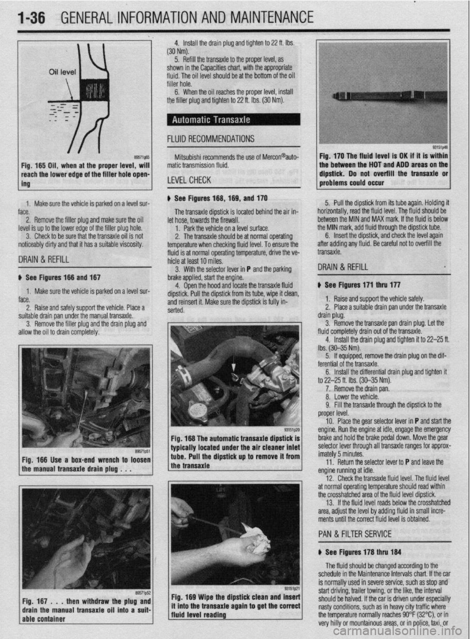
Fig. 170 The fluid level is OK if it is within
the between the HOT and ADD areas on the
&&i& Do not overfill the transaxle or
-.*".."... -- .*"- problems could o ccur
1. Makesure the vehicle is oarked on a level sur-
face.
2. Remove the filler plug and make sure the oil
level is up to the lower edge of the filler plug hole.
3. Check to be sure that the transaxle oil is not
noticeably dirty and that it has a suitable viscosity. u See Figures 168,169, and 170
fluid is at normal operating temperature, drive the ve- The transaxle dipstick is located behind the air in-
hicle at least 10 miles. let hose, towards the firewall.
1. Park the vehicle on a level surface.
2. The transaxle should be at normal operating
temperature when checking fluid level. To ensure the 5. Pull the dipstick from its tube again. Holding it
horizontally, road the fluid level. The fkrid should be
between the MIN and MAX mark. If the fluid is below
the MIN mark, add fluid through the dipstick tube.
DRAIN & REFILL
6. Insert the dipstick, and check the level again
after adding any fluid. Be careful not to overfill the
transaxle.
3. With the selector lever in P and the parking
DRAIN & REFILL u See Figures 166 and 167
1. Make sure the vehicle is parked on a level sur-
face.
2. Raise and safely support the vehicle. Place a brake applied, start the engine.
4. Open the hood and locate the transaxle fluid
dipstick. Pull the dipstick from its tube, wipe it clean,
and reinsert it. Make sure the dipstick is fully in-
serted.
suitable drain pan under the manual transaxle.
3. Remove the filler plug and the drain plug and
allow the oil to drain completely.
Fig. 166 The automatic transaxle dipstick is
typically located under the air cleaner inlet
Fig. 166 Use a box-end wrench to loosen
the manual transaxle drain plug . . . tube. Pull the dipstick up to remove it from
the transaxle
Fig. 169 Wipe the dipstick clean and Insert
/fluid level reading ., it mto the transaxle agam to get the correct
j The fluid should be changed according to the
schedule in the Maintenance Intervals chart. If the car
is normally used in severe service, such as stop and
start driving, trailer towing, or the like, the interval
should be halved. If the car is driven under especially
nasty conditions, such as in heavy city traffic where
the temperature normally reaches 90°F (32%), or in
very hilly or mountainous areas, or in police, taxi, or b See Figures 171 thru 177
1. Raise and support the vehicle safely.
2. Place a suitable drain pan under the transaxle
drain plug.
3. Remove the transaxle pan drain plug. Let the
fluid completely drain out of the transaxle.
4. Install the drain plug and tighten it to 22-25 ft.
lbs. (30-35 Nm).
5. If equipped, remove the drain plug on the dif-
ferential of the transaxle.
6. Install the differential drain plug and tighten ft
to 22-25 ft. Ibs. (30-35 Nm).
7. Remove the drain pan.
8. Lower the vehicle.
9. Fill the transaxle through the dipstick to the
proper level.
10. Place the gear selector lever in P and start the
engine. Run the engine at idle, engage the emergency
brake and hold the brake pedal down. Move the gear
selector lever through all transaxle ranges for approx-
imately 5 minutes.
11. Return the selector lever to P and leave the
engine running at idle.
12. Check the transaxle fluid level. The fluid level
at normal operating temperature should read within
the crosshatched area of the fluid level dipstick.
13. If the fluid level reads below the crosshatched
area, adjust the level by adding fluid in small incre-
ments until the correct fluid level is obtained.
PAN &FILTER SERVICE
b See Figures 178 thru 184
Page 37 of 408
t
1-38 GENERALINFORMATIONAND MAINTENANCE
11 I Add the recommended automatic transaxle
fluid to the transaxle through the dipstick tube. You
will need a long necked funnel, or a funnel and tube
to do this. A quick check of the capacities chart later
in this Section will reveal the capacity of the transaxle
in your vehicle. On a first fill after removing the pan
and filter, this number should be cut into a ‘hand
checked on the dipstick before refilling.
12. With the transaxle in P, put on the parking
brake, block the front wheels, start the engine and let
it idle. DO NOT RACE THE ENGINE. DO NOT MOVE
THE LEVER THROUGH ITS RANGES.
13. With the lever in Park, check the fluid level. If
it’s OK, take the car out for a short drive, park on a
level surface, and check the level again, as outlined
earlier in this section. Add more fluid if necessary. Be
careful not to overfill, which will cause foaming and
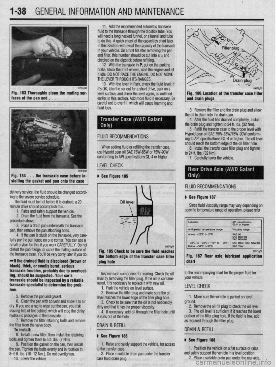
w fluid loss. n of the transfer case filler
3. Remove the filler and the drain plug and allow
the oil to drain into the drain pan.
4. After the fluid has drained completely, install
the drain plug and tighten to 24 ft. Ibs. (32 Nm).
5. Refill the transfer case to the proper level with
Fig. 184 . . .
the transaxle case before in-
stalling the gasket
and pan onto the case FLUID RECOMMENDATIONS Hypoid gear oil SAE 75W-85W/75W-9OW conform-
ing to API specifications GL-4 or higher. The oil level
-‘-,*I’ -nnnh +‘* “%om edge of the oil filler hole.
nxfer raw filler nlm and tinhtm When adding fluid or refilling the transfer case,
use Hypoid gear oil SAE 75W-85W or 75W-9OW
conforming to API specifications 61-4 or higher.
LEVELCHECK 6. Install the tra .._._. ____ .._. T.-J _.._ .lJ . .._..
to 24 ft. lbs. (32 Nm).
7. Carefully lower the vehicle.
u See Figure 185
, 1 FLUID RECOMMENDATIONS
delivery service, the fluid should be changed accord-
ing to the severe service schedule.
The fluid must be hot before it is drained; a 20 u See Figure 187
Since fluid viscosity range may
vary depending on
specific temperature range of operation, please refer
~~
tne transaxle case.
You’ll be very sorry later if you do. bottom edge of the transfer case filler 1 1 Fig. 187 Rear axle lubricant application I
*If the drained fluld is discolored (brown or
1 plug hole chart black), thick, or pmmll~ hmmt nnrinmm I transaxle trouble .llln3llU ““III., url,““P s, probably due to overheat-
,r..rr,rA “#.a.- rrdr
trig, should be susp~~lr;u. lvUl vLlr J
transaxle should be inspected by a reliable
transaxle specialist to determine the prob-
lem.
5. Remove the pan and gasket.
6. Clean the pan with solvent and allow it to air
dry. If you use a rag to wipe out the pan, you risk
leaving bits of lint behind, which will clog the dinky
hydraulic passages in the bansaxle.
7. Remove the filter retaining bolts and remove
the filter from the valve bodv. lnsoect each component for leaking. Check the oil
he filler plug. If the oil is contami-
ry to replace it with new oil.
if% nn IPVPI z11rf2r~
level by removing t
nated, it is necessa
1. Park the vehi,., -.. ,-.“, __. ,“-_.
2. Remove the filler plug and make sure the oil
level reaches the lower edge of the filler plug hole.
3. Check to be sure that the oil is not noticeably
dirty and that it has the proper viscosity.
4. If necessary, add oil through the filler hole until
is runs out of the hole. to the accompanying chart for the proper fluid for
your vehicle.
LEVEL CHECK
1. Make sure the vehicle is parked on level
ground.
2. Remove the oil fill plug to check the oil level.
3. The oil level is sufficient if it reaches the lower
portion of the filler plug hole. If the fluid is low, add
as required through the filler plug.
To install: .
8. Install a new filter, then install the retaining
bolts and tighten them to 5 ft. Ibs. (7 Nm).
9. Position the gasket on the pan, then install
the pan. Tighten the bolts evenly and in rotation to
8-9ft. Ibs. (10-12 Nm.). Do not overtighten.
IO. Lower the vehicle. DRAIN & REFILL
I8 DRAIN & REFILL
u See Figure 188 ) See Figure- 14
1. Raise and safely support the vehicle, for access
to the transfer case.
2. Place a suitable drain pan under the transfer
case fluid drain plug. 1. Position the vehicle on a flat surface or raise
and safely support the vehicle in a level position.
2. Place a suitable drain pan under the rear axle.
Page 46 of 408
GENERAL INFORMATION AND MAINTENANCE 1-47
ramps are also a handy and safe way to both raise l When the drive wheels are to remain on the
and support the vehicle. Be careful though, some ground, leave the vehicle in gear to help prevent it
ramps may be too steep to drive your vehicle onto
The following safety points cannot be overempha- from rolling.
without scraping the front bottom panels. Never sup-
sized:
l Always use jackstands to support the vehicle
port the vehicle on any suspension member (unless l Always block the opposite wheel or wheels to when you are working underneath. Place the stands
specifically instructed to do so by a repair manual) or
keep the vehicle from rolling off the jack. beneath the vehrcle’s jacking brackets Before climb-
by an underbody panel.
l When raising the front of the vehicle, firmly ap- ing underneath, rock the vehicle a bit to make sure it
ply the parking brake. is firmly supported.
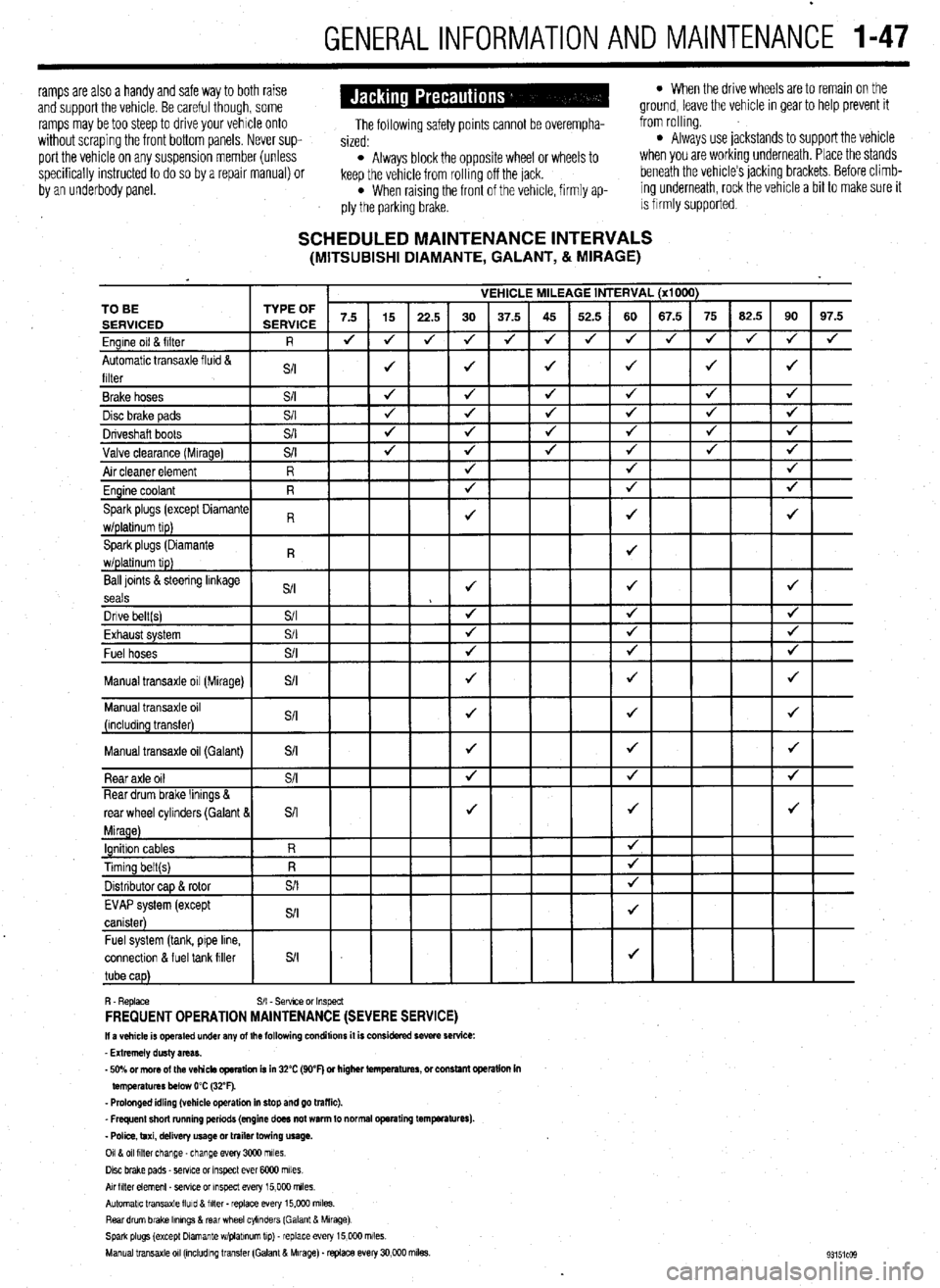
SCHEDULED MAINTENANCE INTERVALS (MITSUBISHI DIAMANTE, GALANT, & MIRAGE)
VEHICLE MILEAGE INTERVAL (x1000)
7.5 15
22.5 30 37.5 45 52.5 60 67.5 75 62.5 90 97.5
J J
J 4 J J 4 4 4 J J
J 4
4
J J J J 4 TO BE
Ball loints &steering linkage
S/I J J J
seals
Dnve belt(s) S/I 4 4 J
Fvha,,rt cvctom $/I
J J J LmI,..“w. “,YL”,‘. Fuel hoses
+
Manual transaxle oil (Galant)
connectlon & fuel tank filler
R. Replace S/I - Sefwce or Inspect FREQUENT OPERATION MAINTENANCE (SEVERE SERVICE) II a vehicle is operated under any of the following conditions it is considered severe service:
- Extremely dusty areas.
- 50% or more of the vehicle operation is in 32% (WF) or higher temperatures, or constant opsralion in
temperatures below 0% (32°F).
- Prolonged idling (vehicle operation in stop and go traffic).
_ Frequent short running periods (engine does not warm to normal operating temfwatures).
- Police, taxi, delivery usage or trailer towing usage.
0118 011 filter change-change every 3CQO miles.
Disc brake pads - sewce or Inspect ever 6COO miles
AN hlter element _ setwe or inspect every 15,000 miles.
Automatic transaxle lluld 8 filter . replace every 15,COO m&s.
Rear drum brake Ikmngs & rear wheel cylinders (Galant & Mirage)
Spark plugs (except Dlamante wlplabnum tip) - replace every 15,COO miles.
Manual transaxle 011 (mcludlng transfer (Galant & Mirage). replace every 30,000 miles.