1900 MITSUBISHI DIAMANTE wheel torque
[x] Cancel search: wheel torquePage 1 of 408
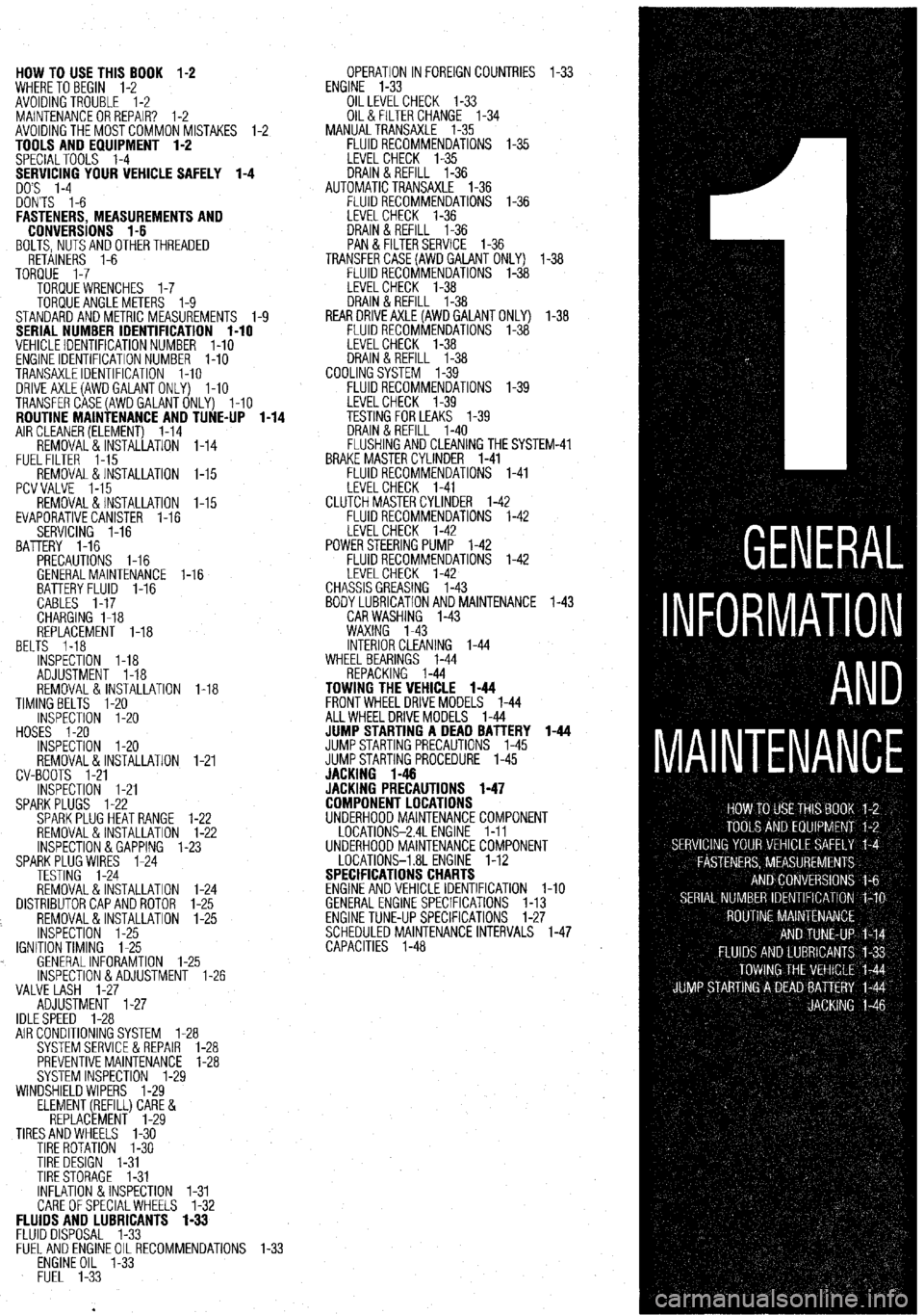
HOW TO USE THIS BOOK 1-2
WHERE TOBEGIN l-2
AVOIDINGTROUBLE 1-2
MAINTENANCEORREPAIR? 1-2
AVOIDINGTHEMOSTCOMMONMISTAKES l-2
TOOLS AND EQUIPMENT 1-2
SPECIALTOOLS l-4
YOUR VEHICLE SAFELY 1-4
DON'TS l-6
FASTENERS, MEASUREMENTS AND
CONVERSIONS l-6
BOLTS,NUTSANDOTHERTHREADED
RETAINERS 1-6
TORQUE l-7
TORQUEWRENCHES l-7
TORQUEANGLEMETERS 1-9
STANDARDANDMETRIC MEASUREMENTS l-9
SERIAL NUMBER IDENTIFICATION l-10
VEHICLE IDENTIFICATION NUMBER l-10
ENGINE IDENTIFICATION NUMBER I-10
TRANSAXLEIDENTIFICATION I-10
DRlVEAXLE(AWDGALANTONLY) l-10
TRANSFERCASE(AWDGALANTONLY) l-10
ROUTINE MAINTENANCE AND TUNE-UP l-14
AIRCLEANER(ELEMENT) 1-14
REMOVAL&INSTALLATION 1-14
FUELFILTER 1-15
REMOVAL &INSTALLATION l-15
PCVVALVE l-15
REMOVAL&INSTALLATION l-15
EVAPORATIVECANISTER l-16
SERVICING 1-16
BATTERY 1-16
PRECAUTIONS I-16
GENERALMAINTENANCE 1-16
BEL BATTERYFLUID 1-16
CABLES I-17
CHARGING I-18
REPLACEMENT 1-18
TS 1-18
INSPECTiON l-18
ADJUSTMENT 1-18
REMOVAL&INSTALLATION 1-18
TIMINGBELTS l-20
INSPECTION l-20
HOSES I-20
INSPECTION l-20
REMOVAL&INSTALLATION
CV-BOOTS 1-21
INSPECTION l-21
SPARKPLUGS l-22
SPARKPLUGHEATRANGE
REMOVAL&INSTALLATION
INSPECTION &GAPPING 1.
SPARKPLUG WIRES 1-24
TESTING 1-24
REMOVAL&INSTALLATION
DISTRIBUTORCAPANDROTOR
REMOVAL&INSTALLATION
INSPECTION 1-25
IGNITIONTIMING 1-25
. GENERALINFORAMTION l-
lNSPECTlON&ADJUSTMENl
VALVE LASH l-27
ADJUSTMENT l-27
IDLESPEED 1-28 1-21
l-22
l-22
-23
1-24
l-25
l-25
.25
1-26
AIR CONDITIONING SYSTEM 1-28
SYSTEMSERVlCEiiREPAlR l-28
PREVENTIVEMAINTENANCE 1-28
SYSTEM INSPECTION l-29
WINDSHIELD WIPERS l-29
ELEMENT(REFILL)CARE&
REPLACEMENT l-29
TIRESANDWHEELS l-30
TIRE ROTATION I-30
TIRE DESIGN 1-31
TIRESTORAGE l-31
INFLATION &INSPECTION l-31
CARE OFSPECIALWHEELS l-32 OPERATION INFOREIGNCOUNTRIES l-33
ENGINE l-33
OILLEVELCHECK 1-33
OIL& FILTER CHANGE l-34
MANUALTRANSAXLE l-35
FLUIDRECOMMENDATIONS l-35
LEVELCHECK l-35
DRAIN&REFILL l-36
AUTOMATICTRANSAXLE l-36
FLUIDRECOMMENDATIONS l-36
LEVELCHECK 1-36
DRAIN&REFILL l-36
PAN & FILTERSERVICE 1-36
TRANSFERCASE(AWDGAlANT ONLY) l-38
FLUIDRECOMMENDATIONS l-38
LEVELCHECK l-38
DRAIN&REFILL l-38
REARDRlVEAXLE(AWDGALANTONLY) l-38
FLUIDRECOMMENDATIONS l-38
LEVELCHECK l-38
DRAIN&REFILL l-38
COOLINGSYSTEM l-39
FLUIDRECOMMENDATIONS l-39
iM-41
FLUIDS AND LUBRICANTS 1-33
FLUID DISPOSAL 1-33
FlJELANDENGlNEOILRECOMMENDATlONS
ENGINE OIL l-33
FUEL l-33
Page 4 of 408
I-4 GENERALINFORMATIONAND MAINTENANCE
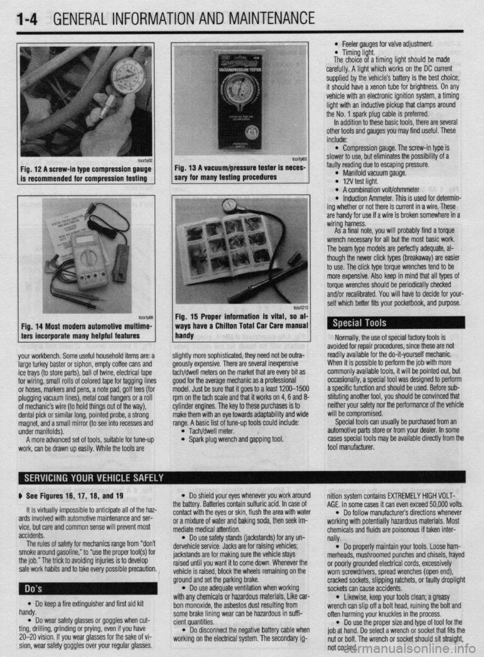
Fig. 12 A screw-in type compression gauge- Fig. 13 A vacuum/pressure tester is neces-
is recommended for compression testing sary for many testing procedures
Fig. 14 Most modern automotive multime-
ters incorporate many helpful features
your workbench. Some useful household items are: a
large turkey baster or siphon, empty coffee cans and
ice trays (to store parts), ball of twine, electrical tape
for wiring, small rolls of colored tape for tagging lines
or hoses, markers and pens, a note pad, golf tees (for
plugging vacuum lines), metal coat hangers or a roll
of mechanic’s wire (to hold things out of the way),
dental pick or similar long, pointed probe, a strong
magnet, and a small mirror (to see into recesses and
under manifolds).
A more advanced set of tools, suitable for tune-up
work, can be drawn up easily. While the tools are
lmvl Fig. 15 Proper information is vital, so at
ways have a Chiiton Total Car Care manua
handy
l Feeler aauoes for valve adiustment
* Timing-light.
The choice of a timing fight should be made
carefully. A light which works on the DC current
supplied by the vehicle’s battery is the best choice;
it should have a xenon tube for brightness. On any
vehicle with an electronic ignition system, a timing
light with an inductive pickup that clamps around
the No. 1 spark plug cable is preferred.
In addition to these basic tools, there are several
other tools and gauges you may find useful. These
include:
l Compression gauge. The screw-in type is
slower to use, but eliminates the possibility of a
fauliy reading due to escaping pressure.
l Manifold vacuum gauge. l 12V test light. l A combination volt/ohmmeter l induction Ammeter. This is used for determin-
ing whether or not there is current in a wire. These
are handy for use if a wire is broken somewhere in a
wiring harness.
As a final note, vou will orobablv find a torque
wrench necessary for all but the most basic work.
The beam type models are perfectly adequate, al-
though the newer click types (breakaway) are easier
to use. The click type torque wrenches tend to be
more expensive. Also keep in mind that all types of
torque wrenches should be periodically checked
and/or recalibrated. You will have to decide for your-
self which better fits your pocketbook, and purpose.
ilightly more sophisticated, they need not be outra-
feously expensive. There are several inexpensive
achldwell meters on the market that are every bit as
Toad for the average mechanic as a professional
nodel. Just be sure that it goes to a least 1200-1500
pm on the tach scale and that it works on 4,6 and 8-
:ylinder engines. The key to these purchases is to
nake them with an eye towards adaptability and wide
ange. A basic list of tune-up tools could include:
l Tach/dwell meter. l Spark plug wrench and gapping tool. Normally, the use of special factory tools is
avoided for repair procedures, since these are not
readily available for the do-it-yourself mechanic.
When it is possible to perform the job with more
commonly available tools, it will be pointed out, but
occasionally, a special tool was designed to perform
a specific function and should be used. Before sub-
stituting another tool, you should be convinced that
neither your safety nor the performance of the vehicle
will be compromised.
Special tools can usually be purchased from an
automotive parts store or from your dealer. In some
cases special tools may be available directly from the
tool manufacturer.
p See Figures 16, 17, 16, and 19
It is virtually impossible to anticipate all of the haz-
ards involved with automotive maintenance and ser-
vice, but care and common sense will prevent most
accidents.
The rules of safety for mechanics range from “don’t
smoke around gasoline,” to “use the proper tool(s) for
the job.” The trick to avoiding injuries is to develop
safe work habits and to take every possible precaution.
Do keep a fire extinguisher and first aid kit
l handy.
Do wear safety glasses or goggles when cut- l ting, drilling, grinding or prying, even if you have
20-20 vision. If you wear glasses for the sake of vi-
sion, wear safety goggles over your regular glasses.
l Do shield your eyes whenever you work around
the battery. Batteries contain sulfuric acid. In case of
contact with the eyes or skin, flush the area with water
or a mixture of water and baking soda, then seek im-
mediate medical attention.
l Do use safety stands (jackstands) for any un-
dervehicle service. Jacks are for raising vehicles;
jackstands are for making sure the vehicle stays
raised until you want it to come down. Whenever the
vehicle is raised, block the wheels remaining on the
ground and set the parking brake.
l Do use adequate ventilation when working
with any chemicals or hazardous materials, Like car-
bon monoxide, the asbestos dust resulting from
some brake lining wear can be hazardous in suffi-
cient quantities.
l Do disconnect the negative battery cable when
working on the electrical system. The secondary ig- nition system contains EXTREMELY HIGH VOLT-
AGE. In some cases it can even exceed 50,000 volts.
l Do follow manufacturer’s directions whenever
working with potentially hazardous materials. Most
chemicals and fluids are poisonous if taken inter-
nally.
l Do properly maintain your tools. Loose ham-
merheads, mushroomed punches and chisels, frayed
or poorly grounded electrical cords, excessively
worn screwdrivers, spread wrenches (open end),
cracked sockets, slipping ratchets, or faulty droplight
sockets can cause accidents.
* Likewise, keep your tools clean; a greasy
wrench can slip off a bolt head, ruining the bolt and
often harming your knuckles in the process.
l Do use the proper size and type of tool for the
job at hand. Do select a wrench or socket that fits the
nut or bolt. The wrench or socket should sit straight,
not cocked.
Page 5 of 408
1-6 GENERALINFORMATIONAND MAINTENANCE
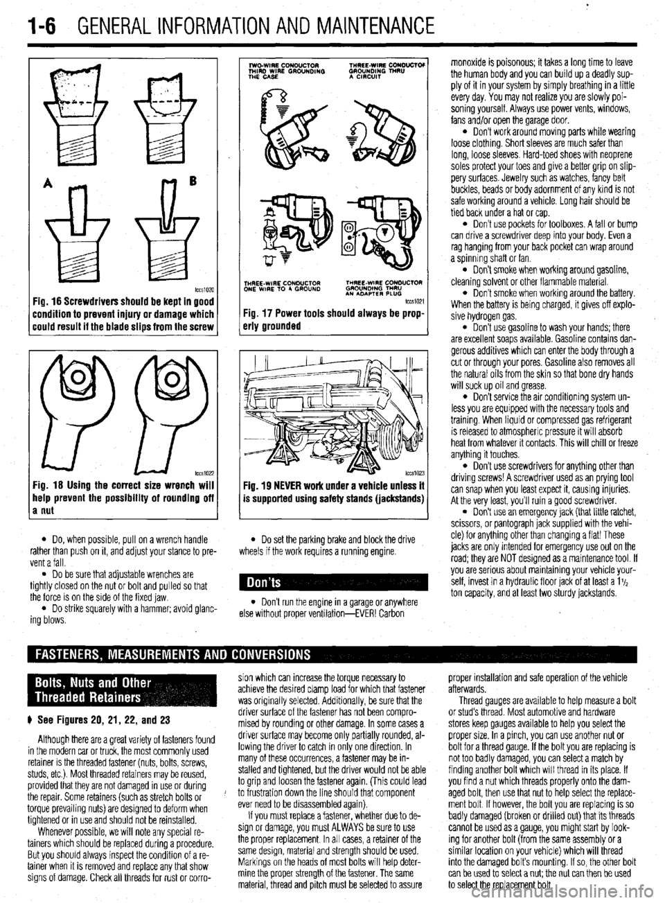
Fig. 16 Screwdrivers should be kept in good
:ondition to prevent injury or damage which
:ould result it the blade slips from the screw
0
0
PP tccs1022 Fig. 16 Using the correct size wrench will
help prevent the possibility of rounding off
a nut
7
lwo.WIRE CouDuClOR TMREE-WIRE CONO”CTOI
MIRD WIRE GROUNDING GROUNDING TNRU
THE CASE A CmxlIT
.
i$Y$$pQ
p-+
TNHREE-WIRE CONDUCTOR THREE-WIRE CONDUCTOR
ONE WIRE TO 4 GROUND GROUNOlNG TMRU
AN ADAPTER PLUG
tccm21
Fig. 17 Power tools should always be prop-
erly grounded
Fig. 19 NEVER work under a vehicle unless it
is supported using safety stands (jackstands)
l Do, when possible, pull on a wrench handle l Do set the parking brake and block the drive
rather than push on it, and adjust your stance to pre-
vent a fall. wheels if the work requires a running engine.
l Do be sure that adjustable wrenches are
tightly closed on the nut or bolt and pulled so that
the force is on the side of the fixed jaw.
l Do strike squarely with a hammer; avoid glanc-
ing blows. l Don’t run the engine in a garage or anywhere
else without proper ventilation-EVER! Carbon monoxide is poisonous; it takes a long time to leave
the human body and you can build up a deadly sup-
ply of it in your system by simply breathing in a !ittle
every day. You may not realize you are slowly poi-
soning yourself. Always use power vents, windows,
fans and/or open the garage door.
l Don’t work around moving parts while wearing
loose clothing. Short sleeves are much safer than
long, loose sleeves. Hard-toed shoes with neoprene
soles protect your toes and give a better grip on slip-
pery surfaces. Jewelry such as watches, fancy belt
buckles, beads or body adornment of any kind is not
safe working around a vehicle. Long hair should be
tied back under a hat or cap.
l Don’t use pockets for toolboxes. A fall or bump
can drive a screwdriver deep into your body. Even a
rag hanging from your back pocket can wrap around
a spinning shaft or fan.
l Don’t smoke when working around gasoline,
cleaning solvent or other flammable material.
l Don’t smoke when workrng around the battery.
When the battery is being charged, it gives off explo-
sive hydrogen gas.
l Don’t use gasoline to wash your hands; there
are excellent soaps available. Gasoline contains dan-
gerous additives which can enter the body through a
cut or through your pores. Gasoline also removes all
the natural oils from the skin so that bone dry hands
will suck up oil and grease.
l Don’t service the air conditioning system un-
less you are equipped with the necessary tools and
trainmg. When liquid or compressed gas refrigerant
is released to atmospheric pressure it will absorb
heat from whatever it contacts. This will chill or freeze
anything it touches.
l Don’t use screwdrivers for anything other than
driving screws! A screwdriver used as an prying tool
can snap when you least expect it, causing injuries.
At the very least, you’ll ruin a good screwdriver.
. Don’t use an emergency jack (that little ratchet,
scissors, or pantograph jack supplied with the vehi-
cle) for anything other than changing a flat! These
jacks are only Intended for emergency use out on the
road; they are NOT designed as a maintenance tool. If
you are serious about mamtaining your vehicle your-
self, invest in a hydraulic floor jack of at least a 1%
ton capacity, and at least two sturdy jackstands.
sion which can increase the torque necessary to proper installation and safe operation of the vehicle
achieve the desired clamp load for which that fastener afterwards.
was originally selected. Additionally, be sure that the Thread gauges are available to help measure a bolt
p See Figures 20, 21, 22, and 23 driver surface of the fastener has not been compro- or stud’s thread. Most automotive and hardware
mised by rounding or other damage. In some cases a stores keep gauges available to help you select the
Although there are a great variety of fasteners found driver surface may become only partially rounded, al- proper size. In a pinch, you can use another nut or
in the modern car or truck, the most commonly used lowing the driver to catch in only one direction. In bolt for a thread gauge. If the bolt you are replacing is
retainer is the threaded fastener (nuts, bolts, screws, many of these occurrences, a fastener may be in- not too badly damaged, you can select a match by
studs, etc.). Most threaded retainers may be reused, stalled and tightened, but the driver would not be able finding another bolt which will thread in its place. If
provided that they are not damaged in use or during to grip and loosen the fastener again. (This could lead you find a nut which threads properly onto the dam-
the repair. Some retainers (such as stretch bolts or J to frustration down the line should that component aged bolt, then use that nut to help select the replace-
torque prevailing nuts) are designed to deform when ever need to be disassembled again). ment bolt If however, the bolt you are replacing is so
tightened or in use and should not be reinstalled. If you must replace a fastener, whether due to de- badly damaged (broken or drilled out) that its threads
Whenever possible, we will note any special re- sign or damage, you must ALWAYS be sure to use cannot be used as a gauge, you might start by look-
tainers which should be replaced during a procedure. the proper replacement In all cases, a retainer of the ing for another bolt (from the same assembly or a
But you should always inspect the condition of a re- same design, material and strength should be used. similar location on your vehicle) which will thread
tainer when It is removed and replace any that show Markings on the heads of most bolts will help deter- into the damaged bolt’s mounting. If so, the other bolt
signs of damage. Check all threads for rust or corro- mine the proper strength of the fastener. The same
can be used to select a nut; the nut can then be used
material, thread and pitch must be selected to assure
to select the replacement bolt.
Page 31 of 408
.
1-32 GENERALINFORMATIONAND MAINTENANCE
CONDITION
EFFECT
CAUSE
CORRECTION UNDER-INFLATION
EXCESSIVE SPEED’ WORN OR OUT-
OF-ALIGNMENT
ADJUST PRESSURE TO
SPECIFICATIONS WHEN
TIRES ARE COOL
ROTATE TIRES
/ BALANCE WHEELS INSPECT SUSPENSION
HAVE TIRE INSPECTED FOR FURTHER USE.
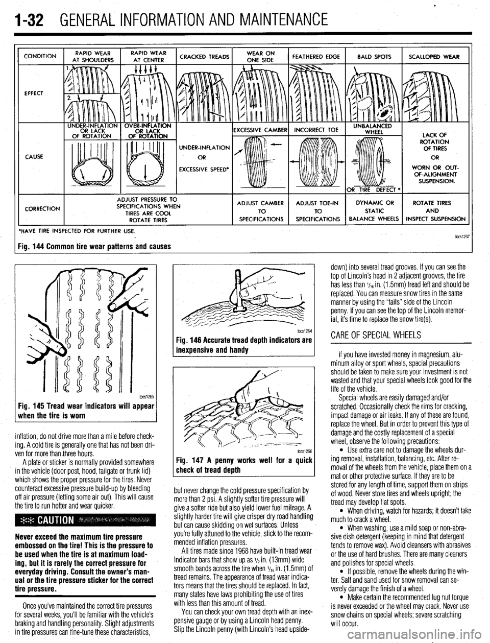
lCCSi267 ig. 144 Common tire wear patterns and causes
1~~~1265 Fig. 145 Tread wear indicators will appear
when the tire is worn
inflation, do not drive more than a mile before check-
ing. A cold tire is generally one that has not been dri-
ven for more than three hours.
A plate or sticker is normally provided somewhere
in the vehicle (door post, hood, tailgate or trunk lid)
which shows the proper pressure for the tires. Never
counteract excessive pressure build-up by bleeding
off air pressure (letting some air out). This will cause
the tire to run hotter and wear quicker.
Never exceed the maximum tire pressure
embossed on the tire! This is the pressure to
be used when the tire is at maximum load-
ing, but it is rarely the correct pressure for
everyday driving. Consult the owner’s man-
ual or the tire pressure sticker for the correct
tire pressure.
Once you’ve maintained the correct tire pressures
for several weeks, you’ll be familiar with the vehicle’s
braking and handling personality. Slight adjustments
in tire pressures can fine-tune these characteristics,
1~~~1264 Fig. 146 Accurate tread depth indicators are
inexuensive and handv
Fig. 147 A penny works well for a quick
check of tread death
but never change the cold pressure specification by
more than 2 psi. A slightly softer tire pressure will
give a softer ride but also yield lower fuel mileage. A
slightly harder tire will give crisper dry road handling
but can cause skidding on wet surfaces. Unless
you’re fully attuned to the vehicle, stick to the recom-
mended inflation pressures.
All tires made since 1968 have built-in tread wear
indicator bars that show up as j/2 in. (13mm) wide
smooth bands across the bre when V,~ in. (1.5mm) of
tread remains. The appearance of tread wear indica-
tors means that the tires should be replaced. In fact,
many states have laws prohibiting the use of tires
with less than this amount of tread.
You can check your own tread depth with an inex-
pensive gauge or by using a Lincoln head penny.
Shp the Lrncoln penny (with Lincoln’s head upside- down) into several tread grooves. If you can see the
top of Lincoln’s head in 2 adjacent grooves, the tire
has less than V,~ in. (1.5mm) tread left and should be
replaced. You can measure snow tires in the same
manner by using the “tails” side of the Lincoln
penny. If you can see the top of the Lincoln memor-
ial, its time to replace the snow tire(s).
CAREOFSPECIALWHEELS
If you have invested money in magnesium, alu-
minum alloy or sport wheels, special precautions
should be taken to make sure your investment is not
wasted and that your special wheels look good for the
life of the vehicle.
Special wheels are easily damaged and/or
scratched. Occasionally check the rims for cracking,
impact damage or air leaks. If any of these are found,
replace the wheel. But in order to prevent this type of
damage and the costly replacement of a special
wheel, observe the following precautions:
l Use extra care not to damage the wheels dur-
ing removal, installation, balancing, etc. After re-
moval of the wheels from the vehicle, place them on a
mat or other protective surface. If they are to be
stored for any length of time, support them on strips
of wood. Never store tires and wheels upright; the
tread may develop flat spots.
l When driving, watch for hazards; it doesn’t take
much to crack a wheel.
l When washing, use a mild soap or non-abra-
sive dish detergent (keeping in mind that detergent
tends to remove wax). Avoid cleansers with abrasives
or the use of hard brushes. There are many cleaners
and polishes for special wheels.
l If possrble, remove the wheels during the win-
ter. Salt and sand used for snow removal can se-
verely damage the finish of a wheel.
l Make certain the recommended lug nut torque
is never exceeded or the wheel may crack. Never use
snow chains on special wheels; severe scratching
will occur.
Page 62 of 408
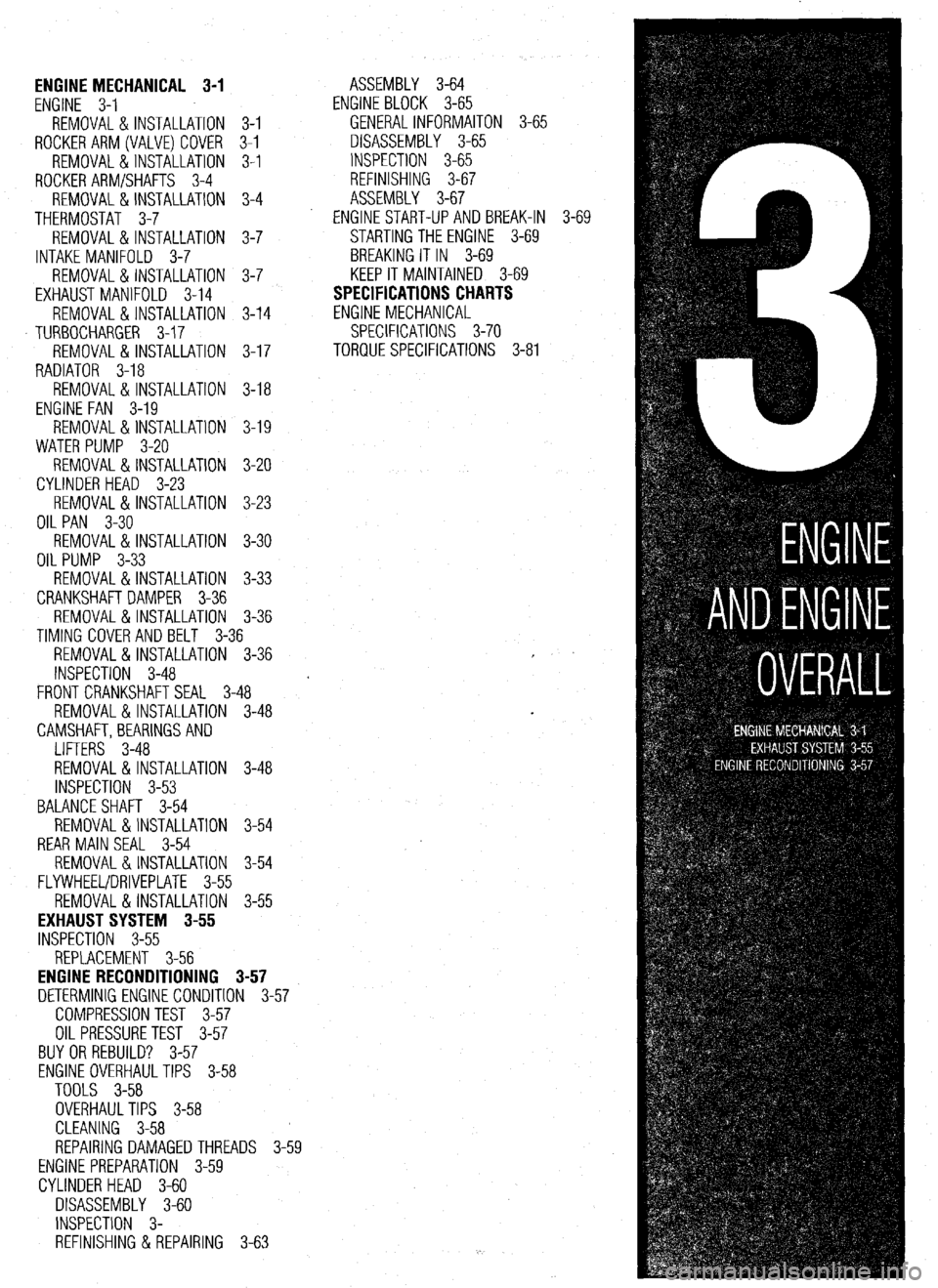
ENGINE MECHANICAL 3-1
ENGINE 3-1
REMOVAL &INSTALLATION 3-l
ROCKERARM(VALVE)COVER 3-l
REMOVAL &INSTALLATION 3-l
ROCKER ARM/SHAFTS 3-4
REMOVAL & INSTALLATION 3-4
THERMOSTAT 3-7
REMOVAL & INSTALLATION 3-7
INTAKE MANIFOLD 3-7
REMOVAL & INSTALLATION 3-7
EXHAUSTMANIFOLD 3-14
REMOVAL &INSTALLATION 3-14
TURBOCHARGER 3-17
REMOVAL & INSTALLATION 3-17
RADIATOR 3-18
REMOVAL & INSTALLATION 3-18
ENGINE FAN 3-19
REMOVAL &INSTALLATION 3-19
WATER PUMP 3-20
REMOVAL & INSTALLATION 3-20
CYLINDER HEAD 3-23
REMOVAL &INSTALLATION 3-23
OIL PAN 3-30
REMOVAL & INSTALLATION 3-30
OIL PUMP 3-33
REMOVAL &INSTALLATION 3-33
CRANKSHAFT DAMPER 3-36
REMOVAL &INSTALLATION 3-36
TIMING COVERAND BELT 3-36
REMOVAL & INSTALLATION 3-36
INSPECTION 3-48
FRONT CRANKSHAFTSEAL 3-48
REMOVAL & INSTALLATION 3-48
CAMSHAFT,BEARlNGSAND
LIFTERS 3-48
REMOVAL & INSTALLATION 3-48
INSPECTION 3-53
BALANCE SHAFT 3-54
REMOVAL &INSTALLATION 3-54
REAR MAIN SEAL 3-54
REMOVAL&INSTALLATION 3-54
FLYWHEEL/DRIVEPLATE 3-55
REMOVAL &INSTALLATION 3-55
EXHAUST SYSTEM 3-55
INSPECTION 3-55
REPLACEMENT 3-56
ENGINE RECONDITIONING 3-57
DETERMINIG ENGINE CONDITION 3-57
COMPRESSION TEST 3-57
OIL PRESSURETEST 3-57
BUYOR REBUILD? 3-57
ENGINE OVERHAULTIPS 3-58
TOOLS 3-58
OVERHAULTIPS 3-58
CLEANING 3-58
REPAIRING DAMAGEDTHREADS 3-59
ENGINE PREPARATION 3-59
CYLINDER HEAD 3-60
DISASSEMBLY 3-60
INSPECTION 3-
REFINISHING & REPAIRING 3-63 ASSEMBLY 3-64
ENGINE BLOCK 3-65
GENERALINFORMAITON 3-65
DISASSEMBLY 3-65
INSPECTION 3-65
REFINISHING 3-67
ASSEMBLY 3-67
ENGINE START-UP AND BREAK-IN 3-
STARTING THE ENGINE 3-69
BREAKING IT IN 3-69
KEEP IT MAINTAINED 3-69
SPECIFICATIONS CHARTS
ENGINE MECHANICAL
SPECIFICATIONS 3-70
TORQUE SPECIFICATIONS 3-81 .69
Page 142 of 408
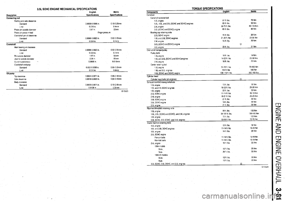
3.5L SOHC ENGINE MECHANICAL SPECIFICATIONS
Description
Connecting rod English
Specifications Metric
Specifications
Rod big end side clearance
Standard
Llrnll
Piston pin outslde dnmeler
P~slon pin press-~” load
Crankshalt pm 011 clearance
Standard 0 0039-o 0096 I” 0 10-O 25mm
0016ln
0 4mm
067rn 22mm
Flngerprewre
0 0006-0 0020 in
0 02-O 05mm
Llmtt
0 004 I” Olmm
Crankshaft
Maln bearing 011 clearance
Standard
0 0006-0 0020 I”
0 02-O 05mm
Llmlt
0 004 I”
Olmm
Pin outside dram&r
197m 50mm
Journal outslde diameter
2361n 60mm
Out-+round (max
) -
0 0006 I”.
0015mm
Crankshaft end.play
Standard
0 002-0 0096 I”.
0 05-O 25mm
TIP clearance
Side clearance
Body clearance
Standard 0
1X24-0 0071 1”
0
0016-O 0039 I” 0 06-O 16mm
0 040 IOmm
0 0039-o 0071 I” 0 10.0.16mm Components
Camshall
TORQUE SPECIFICATIONS English Metric
Camshalt sprwket bolt
1 5L engjne
1 6L, 1 8L, and 2 OL (SOHC and DOHC) engines
2 4L engine
3 OL (SOHC and DOHC) engme
Bearing cap retalnlng bolts
2 OL SOHC engine
1 6L and 2 OL DOHC engines
2 4L eng,ne
3 OL (SOHC and DOHC) engme
3 5L engine
Crankshalt dampedpullev 51 it Ibs
6511 Ibs
56.72 R Ibs.
65 It Ibs
1511 Ibs
21.25ft Ibs
15 fl lbs. 70 Nm
90 Nm
60-l 00 Nm
WNm
2ONm
29-35 Nm
20 Nm
0
23 11 Ibs 31 Nm
Pullev bolts
1 5L engine loft Ibs 14Nm
1 6L and 2 OL (SOHC and DOHC)engines
14.22 It lbs
20-30 Nm
2 4L enqme
16 fl Ibs. 25 Nm
Center reta!ino bolt
51-72 It lbs
13411 Ibs 70.100 Nm
165Nm
3 OL (SOHC and DOHC) engine
Cvllnder head 106-11611 lbs 150-160 Nm
1 6L englne
2 OL SOHC engine
2 4L
engine
3 OL SOHC engine
3 OL DOHC enwe
- 3 5L eqne
Flywheel/dnvaplale retaining b&s 22lt Ibs
11.14ll Ibs
16-21 it Ibs
21 ll Ibs
14 It Ibs
21 It Ibs 3ONm
15-19 Nm
25-29 Nm
29 Nm
19Nm
29 Nm
1 5L engine
1 6L 2 OL (SOHC and DOHC), and 2 4L engmes 98 It Ibs
94.101 II Ibs 135Nm
130-140 Nm
1 6L
engine 72 It lbs
100 Nm
3 OL SOHC, 3 OL DOHC, and 3 5L engmes
53-56 It Ibs
72-76 Nm
Intake manlfoid retanmg bolts
1 5L engine
16Land20L DOHC engines 1311 lbs
Ii-141 Ibs 16Nm
15-19 Nm
1 6L engine
2 OL SOHC engme
Plenum bolts
Manifold bolts
2 4L
eng,ne
1994 models 1411 Ibs
11.14R Ibs.
11-1411 Ibs
left Ibs 15.19Nm
15.19Nm
25 Nm
Bolts
NUk
1995.00 models 15fl ibs 20 Nm
26 ‘I lbs.
35 Nm
SOItS 15fi Ibs 20 Nm
Nuts
15 ft Ibs.
20 Nm
3 OL SOHC 3 OL DOHC, and 3 5L engines
0
93153~24
m
F5
/ m
P
0
m
is
7
m
Page 201 of 408
.
5-14 FUEL SYSTEM
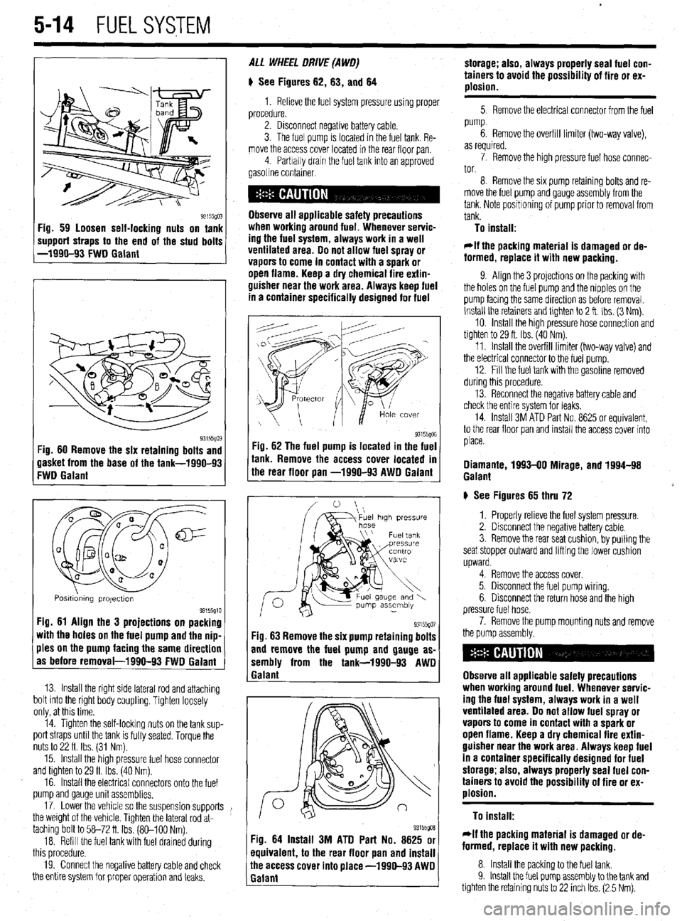
93155(10: ‘ig. 59 loosen self-locking nuts on tank
mpporf straps to the end of the stud bolts
-1990-93 FWD Galant
93i55Qo$ :ig. 60 Remove the six retaining bolts and
lasket from the base of the tank-1990-93
:WD Galant
Q m
0 a
cl@=
u a-
a al2
0
0
Q
a a
Posmdmng projectton 93155910 Fig. 61 Align the 3 projections on packing
with the holes on the fuel pump and the nip-
ples on the pump facing the same direction
as before removal-1990-93 FWD Galant
13. Install the right side lateral rod and attaching
bolt into the right body coupling. Tighten loosely
only, at this time.
14. Tighten the self-locking nuts on the tank sup-
port straps until the tank is fully seated. Torque the
nuts to 22 ft. Ibs. (31 Nm).
15. Install the high pressure fuel hose connector
and tighten to 29 ft. Ibs. (40 Nm).
16. Install the electrical connectors onto the fuel
pump and gauge unit assemblies.
17. Lower the vehicle so the suspension supports
the weight of the vehicle. Tighten the lateral rod at-
taching bolt to 58-72 ft Ibs. (So-100 Nm).
18. Refill the fuel tank with fuel drained during
this procedure.
19. Connect the negative battery cable and check
the entire system for proper operation and leaks. ALL WHEEL DRIVE (A WO)
# See Figures 62, 63, and 64
1. Relieve the fuel system pressure using proper
procedure.
2. Disconnect negative battery cable.
3. The fuel pump is located in the fuel tank. Re-
move the access cover located in the rear floor pan
4 Parbally drain the fuel tank into an approved
gasoline container.
Observe all applicable safety precautions
when workina around fuel. Whenever servic-
ing the fuel system, always work in a well
ventilated area. Do not allow fuel spray or
vapors to come in contact with a spark or
open flame. Keep a dry chemical fire extin-
guisher near the work area. Always keep fuel
in a container specifically designed for fuel
-ig. 62 The fuel pump is located in the fuel
r
ank. Remove the access cover located m
he rear floor pan -1990-93 AWD Galant
93155go7 Fig. 63 Remove the six pump retaining bolts
and remove the fuel pump and gauge as-
sembly from the tank-1990-93 AWD
1 Galant
93155goa Fig. 64 Install 3M ATD Part No. 8625 or
equivalent, to the rear floor pan and install
ihe access cover into place -1990-93 AWD
Ealant storage; also, always properly seal fuel con-
tainers to avoid the possibility of fire or ex-
plosion.
5 Remove the electrical connector from the fuel
pump.
6. Remove the overfill limiter (two-way valve),
as required.
7. Remove the high pressure fuel hose connec-
tor.
8. Remove the six pump retaming bolts and re-
move the fuel pump and gauge assembly from the
tank. Note positioning of pump prior to removal from
tank.
To install:
*If the packing material is damaged or de-
formed, replace it with new packing.
9. Align the 3 projections on the packing with
the holes on the fuel pump and the nipples on the
pump facmg the same direction as before removal.
Install the retainers and tlghten to 2 ft. Ibs. (3 Nm).
10. Install the high pressure hose connection and
tighten to 29 ft. Ibs. (40 Nm).
11. Install the overfill limiter (two-way valve) and
the electrical connector to the fuel pump.
12. Fill the fuel tank with the gasoline removed
during this procedure.
13. Reconnect the negative battery cable and
check the entire system for leaks.
14. Install 3M ATD Part No. 8625 or equivalent,
to the rear floor pan and install the access cover into
place.
Diamante, 1993-00 Mirage, and 1994-98
Galant
# See Figures 65 thru 72
1. Properly relieve the fuel system pressure.
2. Disconnect the negative battery cable.
3. Remove the rear seat cushion, by pulling the
seat stopper outward and lifting the lower cushion
upward.
4. Remove the access cover.
5. Disconnect the fuel pump wiring.
6. Disconnect the return hose and the high
pressure fuel hose.
7. Remove the pump mounting nuts and remove
the pump assembly.
Observe all applicable safety precautions
when working around fuel. Whenever servic-
ing the fuel system, always work in a well
ventilated area. Do not allow fuel spray or
vapors to come in contact with a spark or
open flame. Keep a dry chemical fire extin-
guisher near the work area. Always keep fuel
in a container specifically designed for fuel
storage; also, always properly seal fuel con-
tainers to avoid the possibility of fire or ex-
plosion.
To install:
rlf the packing material is damaged or de-
formed, replace it with new packing.
8. Install the packing to the fuel tank.
9. Install the fuel pump assembly to the tank and
tighten the retaining nuts to 22 inch Ibs. (2 5 Nm).
Page 281 of 408
7-2 'DRIVETRAIN
Because of the way an internal combustron engine
breathes, it can produce torque, or twisting force,
only within a narrow speed range. Most modern,
overhead valve pushrod engines must turn at about
2500 rpm to produce their peak torque By 4500 rpm
they are producrng so lrttle torque that contrnued in-
creases in engine speed produce no power increases.
The torque peak on overhead camshaft engines IS
generally much higher, but much narrower.
The manual transaxle and clutch are employed to
vary the relationship between engine speed and the
speed of the wheels so that adequate engine power can
be produced under all crrcumstances. The clutch al-
lows engine torque to be applied to the transaxle input
shaft gradually, due to mechanical slippage. Conse-
quently, the vehicle may be started smoothly from a
full stop The transaxle changes the ratio between the
rotating speeds of the engine and the wheels by the
use of gears. The gear ratios allow full engine power to
be applied to the wheels during acceleration at low
speeds and at highway/passing speeds.
In a front wheel drive transaxle, power is usually
transmitted from the input shaft to a mainshaft or out-
put shaft located slightly beneath and to the side of
the input shaft. The gears of the mainshaft mesh with
gears on the input shaft, allowing power to be carried
from one to the other. All forward gears are in con-
stant mesh and are free from rotating with the shaft
unless the synchronizer and clutch IS engaged. Shaft-
ing from one gear to the next causes one of the gears
to be freed from rotating with the shaft and locks an-
other to it. Gears are locked and unlocked by internal
dog clutches which slide between the center of the
gear and the shaft. The forward gears employ syn-
chronizers; friction members which smoothly bring
gear and shaft to the same speed before the toothed
dog clutches are engaged.
SHIFT LINKAGE
1. Disconnect the shift linkage from the transaxle.
2. On the transaxle, put select lever in N and
move the shift lever in
4th gear. Depress the clutch,
if necessary, to shift.
3. Move the shift lever in the vehicle to the
4th gear position until it contacts the stop.
4. Turn the adjuster turnbuckle so the shift cable
eye aligns with the eye in the gear shift lever. When
installing the cable eye, make sure the flange side of
the plastic bushing at the shift cable end is on the
cotter pin side.
5 The cables should be adjusted so the clear-
ance between the shift lever and the 2 stoppers are
equal when the shift lever IS moved to 3rd and 4th
gear. Move the shift lever to each positron and check i
that the shifting is smooth
REMOVAL &INSTALLATION
1, Disconnect the negative battery cable 2. Remove any components necessary to access
the back-up light switch.
3. Unplug the back-up light switch connector.
4. Remove the switch from the case using the ap-
propriate size socket and drive tool.
To install: 5. Install the switch and tighten it to 22-25 ft. Ibs.
(30-35 Nm).
6. Attach the back-up light switch connector
7. Install any components removed to access the
back-up light switch
8. Connect the negative battery cable.
REMOVAL & INSTALLATION
Mirage
*If the vehicle is going to be roiled while the
halfshafts are out of the vehicle, obtain 2 outer
CV-joints or proper equivalent tools and install
to the hubs. If the vehicle is rolled without the
proper torque applied to the front wheel bear-
ings, the bearings will no longer be usable.
*The suspension components should not be
tightened until the vehicles weight is resting
on the ground.
1. Remove the battery and battery tray.
2. Remove the air cleaner assembly and vacuum
hoses.
3. Note the locations and disconnect the shifter
cables.
4. If equipped with 1.61 engine, remove the ten-
sion rod.
5. Detach the backup lamp switch connector,
speedometer cable connection and remove the starter
motor.
6. Raise the vehicle and support safely.
7. Remove the front wheels and the inner wheel
panels.
8. Remove the undercover and splash pan.
9. Drain the transaxle oil into a suitable con-
tainer
10. Support the engine and remove the cross-
member.
11. Remove the upper transaxle mounting bolt
and bracket.
12 Disconnect the stabilizer bar, tie rod ends and
the lower ball joint connections.
13 Remove the clutch release cylinder and clutch
oil line bracket. Do not disconnect the fluid lines and
secure the slave cylinder with wire.
14 Disconnect the clutch cable, if equipped with
cable controlled clutch system.
15. Remove the halfshafts by inserting a prybar
between the transaxle case and the driveshaft and
prying the shaft from the transaxle. Do not pull on the
driveshaft Doing so damages the inboard joint. Do
not insert the prybar so far the oil seal in the case is
damaged.
*It is not necessary to disconnect the half-
shafts from the steering knuckle. Remove the
shaft with the hub and knuckle as an assem-
bly. Tie the shafts aside. Note the circle clip
on the end of the inboard shafts should not
be reused.
16. Remove the bellhousing lower cover.
17 Remove the transaxle to engine bolts and
lower the transaxle from the vehrcle.
To install:
*When installing the transaxle, be sure to
align the splines of the transaxle with the
clutch disc.
18 Install the transaxle to the engine and install
the mounting bolts. Tighten the bolts to 31-40 ft. Ibs.
(43-55 Nm) on 1990-92 models and 35 ft. Ibs. (48
Nm) on 1993-00 models.
19 Install the bellhousing cover.
*When installing the halfshafts, use new
circlips on the axle ends. Care must be taken
to ensure that the oil seal lip of the transaxle
is not damaged by the serrated part of the
driveshaft.
20. Install and fully seat the halfshafts into the
transaxle.
21. Install the slave cylinder.
22. Connect the ball joints, tie rod ends and the
stabilizer bar connections.
23. Install the upper transaxle mounting bracket
and bolt.
24. Install the crossmember.
25. Install the undercover.
26. Install the upper transaxle-to-engine mount-
ing bolts, Tighten the bolts to 31-40 ft. Ibs. (43-55
Nm) on 199C-92 models and 35 ff. Ibs. (48 Nm) on
1993-00 models.
27. Install the starter motor.
28 Connect the backup light switch connector
and speedometer cable.
29 Connect and adjust the shifter cables.
30 Install the air cleaner assembly.
31. Install the front wheels.
32 Make sure the vehicle is level when refilling
the transaxle Use Hypoid gear oil or equivalent, GL-
4 or higher.
33. Connect the negative battery cable and check
the transaxle for proper operation. Make sure the re-
verse lights operate when in reverse.
Galant
1999-93 MODELS
rlf the vehicle is going to be rolled on its
wheels while the halfshafts are out of the ve-
hicle, obtain two outer CV-joints or proper
equivalent tools and install to the hubs. If the
vehicle is rolled without the proper torque
applied to the front wheel bearings, the bear-
ings will no longer be usable.
1. Remove the battery and the air intake hoses.
2. If equipped with Active-ECS, unplug the
compressor wiring.
3. Remove the auto-cruise actuator and under-
hood bracket, located on the passenger side inner
fender well.
4. Drain the transaxle and transfer case fluid, if
equipped, into a suitable waste container.
5. Remove the retainer bolt and pull the
speedometer cable from the transaxle assembly.
6. Remove the cotter pin securing the select and
shift cables and remove the cable ends from the
transaxle.