1900 MITSUBISHI DIAMANTE key
[x] Cancel search: keyPage 4 of 408
I-4 GENERALINFORMATIONAND MAINTENANCE
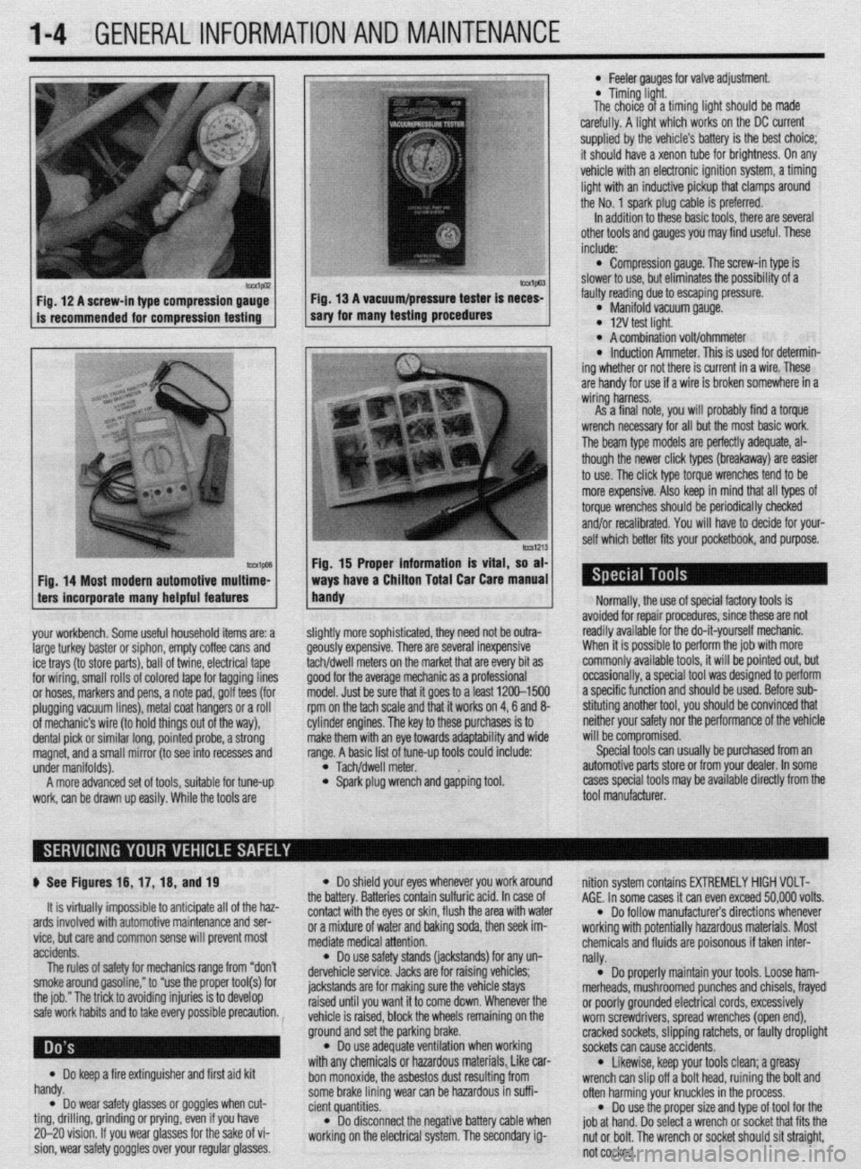
Fig. 12 A screw-in type compression gauge- Fig. 13 A vacuum/pressure tester is neces-
is recommended for compression testing sary for many testing procedures
Fig. 14 Most modern automotive multime-
ters incorporate many helpful features
your workbench. Some useful household items are: a
large turkey baster or siphon, empty coffee cans and
ice trays (to store parts), ball of twine, electrical tape
for wiring, small rolls of colored tape for tagging lines
or hoses, markers and pens, a note pad, golf tees (for
plugging vacuum lines), metal coat hangers or a roll
of mechanic’s wire (to hold things out of the way),
dental pick or similar long, pointed probe, a strong
magnet, and a small mirror (to see into recesses and
under manifolds).
A more advanced set of tools, suitable for tune-up
work, can be drawn up easily. While the tools are
lmvl Fig. 15 Proper information is vital, so at
ways have a Chiiton Total Car Care manua
handy
l Feeler aauoes for valve adiustment
* Timing-light.
The choice of a timing fight should be made
carefully. A light which works on the DC current
supplied by the vehicle’s battery is the best choice;
it should have a xenon tube for brightness. On any
vehicle with an electronic ignition system, a timing
light with an inductive pickup that clamps around
the No. 1 spark plug cable is preferred.
In addition to these basic tools, there are several
other tools and gauges you may find useful. These
include:
l Compression gauge. The screw-in type is
slower to use, but eliminates the possibility of a
fauliy reading due to escaping pressure.
l Manifold vacuum gauge. l 12V test light. l A combination volt/ohmmeter l induction Ammeter. This is used for determin-
ing whether or not there is current in a wire. These
are handy for use if a wire is broken somewhere in a
wiring harness.
As a final note, vou will orobablv find a torque
wrench necessary for all but the most basic work.
The beam type models are perfectly adequate, al-
though the newer click types (breakaway) are easier
to use. The click type torque wrenches tend to be
more expensive. Also keep in mind that all types of
torque wrenches should be periodically checked
and/or recalibrated. You will have to decide for your-
self which better fits your pocketbook, and purpose.
ilightly more sophisticated, they need not be outra-
feously expensive. There are several inexpensive
achldwell meters on the market that are every bit as
Toad for the average mechanic as a professional
nodel. Just be sure that it goes to a least 1200-1500
pm on the tach scale and that it works on 4,6 and 8-
:ylinder engines. The key to these purchases is to
nake them with an eye towards adaptability and wide
ange. A basic list of tune-up tools could include:
l Tach/dwell meter. l Spark plug wrench and gapping tool. Normally, the use of special factory tools is
avoided for repair procedures, since these are not
readily available for the do-it-yourself mechanic.
When it is possible to perform the job with more
commonly available tools, it will be pointed out, but
occasionally, a special tool was designed to perform
a specific function and should be used. Before sub-
stituting another tool, you should be convinced that
neither your safety nor the performance of the vehicle
will be compromised.
Special tools can usually be purchased from an
automotive parts store or from your dealer. In some
cases special tools may be available directly from the
tool manufacturer.
p See Figures 16, 17, 16, and 19
It is virtually impossible to anticipate all of the haz-
ards involved with automotive maintenance and ser-
vice, but care and common sense will prevent most
accidents.
The rules of safety for mechanics range from “don’t
smoke around gasoline,” to “use the proper tool(s) for
the job.” The trick to avoiding injuries is to develop
safe work habits and to take every possible precaution.
Do keep a fire extinguisher and first aid kit
l handy.
Do wear safety glasses or goggles when cut- l ting, drilling, grinding or prying, even if you have
20-20 vision. If you wear glasses for the sake of vi-
sion, wear safety goggles over your regular glasses.
l Do shield your eyes whenever you work around
the battery. Batteries contain sulfuric acid. In case of
contact with the eyes or skin, flush the area with water
or a mixture of water and baking soda, then seek im-
mediate medical attention.
l Do use safety stands (jackstands) for any un-
dervehicle service. Jacks are for raising vehicles;
jackstands are for making sure the vehicle stays
raised until you want it to come down. Whenever the
vehicle is raised, block the wheels remaining on the
ground and set the parking brake.
l Do use adequate ventilation when working
with any chemicals or hazardous materials, Like car-
bon monoxide, the asbestos dust resulting from
some brake lining wear can be hazardous in suffi-
cient quantities.
l Do disconnect the negative battery cable when
working on the electrical system. The secondary ig- nition system contains EXTREMELY HIGH VOLT-
AGE. In some cases it can even exceed 50,000 volts.
l Do follow manufacturer’s directions whenever
working with potentially hazardous materials. Most
chemicals and fluids are poisonous if taken inter-
nally.
l Do properly maintain your tools. Loose ham-
merheads, mushroomed punches and chisels, frayed
or poorly grounded electrical cords, excessively
worn screwdrivers, spread wrenches (open end),
cracked sockets, slipping ratchets, or faulty droplight
sockets can cause accidents.
* Likewise, keep your tools clean; a greasy
wrench can slip off a bolt head, ruining the bolt and
often harming your knuckles in the process.
l Do use the proper size and type of tool for the
job at hand. Do select a wrench or socket that fits the
nut or bolt. The wrench or socket should sit straight,
not cocked.
Page 13 of 408
l
l-14 GENERALINFORMATIONAND MAINTENANCE
Proper maintenance and tune-up is the key to long
and trouble-free vehicle life, and the work can yield
its own rewards. Studies have shown that a properly
tuned and maintained vehicle can achieve better gas
mileage than an out-of-tune vehicle. As a conscien-
tious owner and driver, set aside a Saturday morning,
say once a month, to check or replace items which
could cause major problems later. Keep your own
personal log to jot down which services you per-
formed, how much the parts cost you, the date, and
the exact odometer reading at the time. Keep all re-
selfer, these receipts are the only proof you have that ceipts for such items as engine oil and filters, so that
they may be referred tp in case of related problems or
to determine operating expenses. As a do-it-your- the required maintenance was performed. In the event
of a warranty problem, these receipts will be invalu-
able.
The literature provided with your vehicle when it
was originally delivered includes the factory recom-
mended maintenance schedule. If you no longer have
this literature, replacement copies are usually avail-
able from the dealer. A maintenance schedule is pro-
vided later in this section, in case you do not have
the factory literature. *
REMOVAL &INSTALLATION
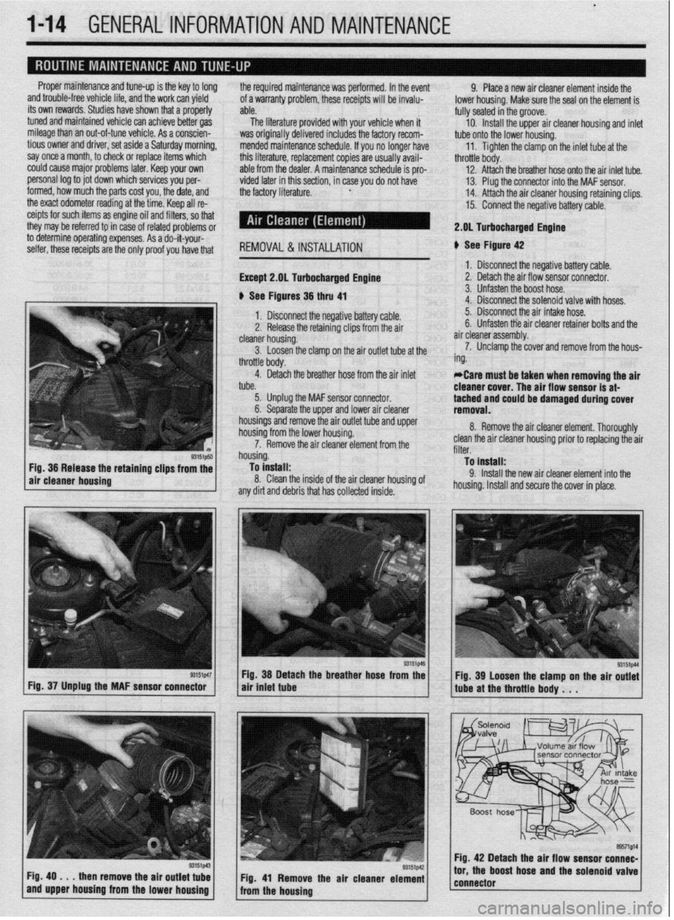
Except 2.gL Turbocharged Engine
b See Figures 36 thru 41 9. Place a new air cleaner element inside the
lower housing. Make sure the seal on the element is
fully seated in the groove.
10. Install the upper air cleaner housing and inlet
tube onto the lower housing.
11. Tighten the clamp on the inlet tube at the
throttle body.
12. Attach the breather hose onto the air inlet tube.
13. Plug the connector into the MAF sensor.
14. Attach the air cleaner housing retaining clips.
15. Connect the negative battery cable.
2.DL Turbocharged Engine
b See Figure 42
1. Disconnect the negative battery cable.
2. Detach the air flow sensor connector.
3. Unfasten the boost hose.
4. Disconnect the solenoid valve with hoses.
93151p50 Fig. 36 Release the retaining clips from the
air cleaner housing
r3151p47 Fig. 37 Unplug the MAF sensor connector
Fig. 49
. . . then remove the air outlet tube
and upper housing from the lower housing 1. Disconnect the negative battery cable. 5. Disconnect the air intake hose.
2. Release the retaining clips from the air 6. Unfasten tie air cleaner retainer bolts and the
cleaner housing. air cleaner assembly.
3. Loosen the clamp on the air outlet tube at the 7. Unclamp the cover and remove from the hous-
throttle body. ing.
4. Detach the breather hose from the air inlet
tube. *Care must be taken when removing the air
cleaner cover. The air flow sensor is at-
5. Unplug the MAF sensor connector.
6. Separate the upper and lower air cleaner tached and could be damaged during cover
removal.
housings and remove the air outlet tube and upper
housing from the lower housing.
7. Remove the air cleaner element from the
housing.
To install:
8. Clean the inside of the air cleaner housing of
any dirt and debris that has collected inside. 8. Remove the air cleaner element. Thoroughly
clean the air cleaner housing prior to replacing the air
filter.
To install:
9. Install the new air cleaner element into the
housing. Install and secure the cover in place.
Fig. 38 Detach the breather hose from the
air tniet tube
Fig. 41 Remove the air cleaner element
from the housing Fig. 39 Loosen the clamp on the air outlet
tube at the throttle body . . .
Fig. 42 Detach the air flow sensor connec-
tor, the boost hose and the solenoid valve
connector
Page 14 of 408
GENERALINFORMATIONAND MAINTENANCE l-15
10. install the air cleaner assembly and the re- *Wrap shop towels around the fitting that is
tainer bolts. being dtsconnected to absorb residual fuel in
11. Connect the air intake hose. the lines. 9. While holding the fuel filter nut with aback-
up wrench, tighten the banjo bolt to 22 ft. Ibs. (30
Nm). Tighten the flare nut to 25 ft. Ibs. (35 Nm), with
12. Attach the solenoid valve.
4. Cover the hose connection with shop towels to a back-up wrench on the nut.
13. Connect the boost hose.
14. Attach the air flow sensor connector. prevent any splash of fuel that could be caused by 10. Tighten the filter mounting bolts to 10 ft. Ibs.
residual pressure in the fuel pipe line. Hold the fuel (14 Nm).
15. Connect the negative battery cable. 11.
filter nut securely with a backup wrench, then remove Connect the negative battery cable. Turn the
REMOVAL &INSTALLATION the banjo bolt on the engine feed line. Disconnect the
high-pressure fuel line from the filter. Remove and
discard the gaskets.
5. While holding the fuel filter nut securely with a
back-up wrench, loosen the filter feed pipe flare nut key to the ON position to pressurize the fuel system
and check for leaks.
12. If repairs of a leak are required, remember to
release the fuel pressure before opening the fuel sys-
tern.
u See Figures 43 thru 48
On most vehicles covered by this manual, the fuel
filter is located in the engine compartment, mounted
to the firewall.
Do not use conventional fuel filters, hoses or
clamps when servicing fuel injection sys
terns. They are not compatible with the injec-
tion
system and could fail, causing personal
injury or damage to the vehicle. Use only
hoses and clamps specifically designed for
fuel injection systems.
1. Properly relieve the fuel system pressure as
outlined in Section 5 of this manual. on the bottom of the filter. Separate the flare nut con-
nection from the filter. If equipped, remove and dis-
card the gaskets.
6. Remove the mounting bolts and remove
. ,,,. ,.
.a r I,.,< I the
ruer rrrter. II necessary, remove me ruer rrrrer oracket.
To install:
7. Install the filter to its bracket only finger-tight.
Movement of the filter will ease attachment of the fuel
lines.
Ensure that the filter is installed with the flow
arrow in the proper direction. The flow arrow
typically points toward the engine side of the
filter. improper installation of the fuel filter
will cause the vehicle to run poorly.
2. If not already done, disconnect the negative REMOVAL&INSTALLATION
u See Figures 49, 50, and 51
1, Disconnect the negative battery cable.
2. If necessary for access, remove the air intake
hose and air cleaner assembly.
3. If necessary, unfasten the retaining clamp, then
disconnect the ventilation hose from the PCV valve.
4. Remove the PCV valve from the camshaft
(rocker) cover.
To install:
5. Install the PCV valve into the rocker cover. If
the valve is threaded, tighten the valve until snug.
battery cable.
3. On most models. the iob is made easier if the
air inlet hose and upper air cleaner housing is re-
moved from the vehicle. *Make sure new O-rings are installed prior
to installation.
8. Insert the filter feed pipe to the lower connec-
tion of the filter and manually screw in the main
pipe’s flare nut. 6. Reconnect the ventilation hose to the valve.
7. If removed, install the air intake hose and the
a .ir cleaner assembly.
8. Connect the negative battery cable.
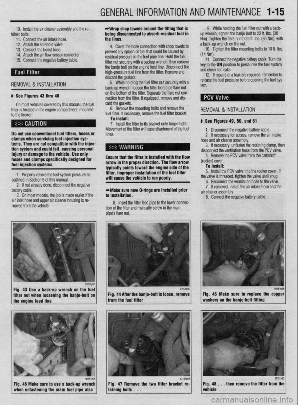
Fig. 43 Use a back-up wrench on the fuel
I I
93151@3
filter nut when loosening the banjo-bolt on Fig. 44 After the banjo-bolt is loose, remove
I
1 the engine feed line - from the fuel filter
93151p93 Fig. 48 Make sure to use a back-up wrench
1 when unfastening the main fuel pipe also 1 Fig. 47 Remove the two filter bracket re-
taining bolts . . . Fig. 45 Make sure to replace the copper
washers on the banjo-bolt fitting
Fig. 48 . . . then remove the filter from the
vehicle
Page 44 of 408
GENERALINFORMATIONAND MAINTENANCE 1-45
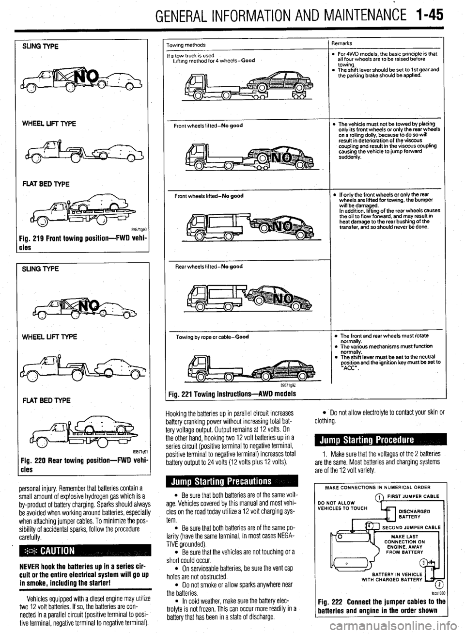
SLING TYPE
WHEEL LIFT TYPE
cles
SUNG TYPE
WHEEL LIFT TYPE
FLAT BED TYPE
Fig. 220 Rear towing position-FWD vehi
cles
personal injury. Remember that batteries contain a
small amount of explosive hydrogen gas which is a
by-product of battery charging. Sparks should always
be avoided when working around batteries, especially
when attaching jumper cables. To minimize the pos-
sibility of accidental sparks, follow the procedure
carefully.
NEVER hook the batteries up in a series cir-
cuit or the entire electrical system will go up
in smoke. includino the starter!
Vehicles equipped with a diesel engine may utilize
two 12 volt batteries. If so, the batteries are con-
nected in a parallel circuit (positive terminal to posi-
tive terminal, negative terminal to negative terminal).
owrng methods
a tow truck IS used
Lrftrng method for 4 wheels-Good
Front wheels lifted-No good
Front wheels lifted-No good
Rear wheels lifted-No good
Towing by rope or cable-Good
e9571g92 qemarks
. For4WD models, the basic principle is that
all four wheels are to be rarsed before
towing.
. The shift lever should be set to 1 st gear and
the parking brake should be applied.
l The vehicle must not be towed by tofacing
only its front wheels or only the rear wheels
on a rollino dollv, because to do so will
result in d&e&ration of the visfx~s
coupling and result in the viscous coupling
causing the vehicle to jump forward
suddenly.
l If only the front wheels or only the rear
wheels are lifted for towing, the bumper
wrll bedamyd.
In addrtron. II trng of the rear wheels causes
the or1 to flow forward. and may result in
heat damage to the rear bushing of the
transfer, and so should never be done.
l The front and rear wheels must rotate
normally.
l The various mechanisms must function
normally.
l The shift lever must be set to the neutral
~Asi&n and the ignition key must be set to
Fig. 221 Towing instructions-AWD models
Hooking the batteries up in parallel circuit increases
battery cranking power without increasing total bat-
tery voltage output. Output remains at 12 volts. On
the other hand, hooking two 12 volt batteries up in a
series circuit (positive terminal to negative terminal,
positive terminal to negative terminal) increases total
battery output to 24 volts (12 volts plus 12 volts).
l Be sure that both batteries are of the same volt-
age. Vehicles covered by this manual and most vehi-
cles on the road today utilize a 12 volt charging sys-
tem.
l Be sure that both batteries are of the same po-
larity (have the same terminal, in most cases NEGA-
TIVE grounded).
l Be sure that the vehicles are not touching or a
short could occur.
l On serviceable batteries, be sure the vent cap
holes are not obstructed.
l Do not smoke or allow sparks anywhere near
the batteries.
l In cold weather, make sure the battery elec-
trolyte is not frozen, This can occur more readily in a
battery that has been in a state of discharge.
l Do not allow electrolyte to contact your skin or
clothing.
1. Make sure that the voltages of the 2 batteries
are the same. Most batteries and charging systems
are of the 12 volt variety.
MAKE CONNECTIONS IN NUMERICAL ORDER
A FIRST JUMPER CABLE
WITH CHARGED BATTERY
-
lccslQ?,Q
Fig. 222 Connect the jumper cables to the
batteries and engine in the order shown
Page 54 of 408
ENGINEELECTRICAL 2-7
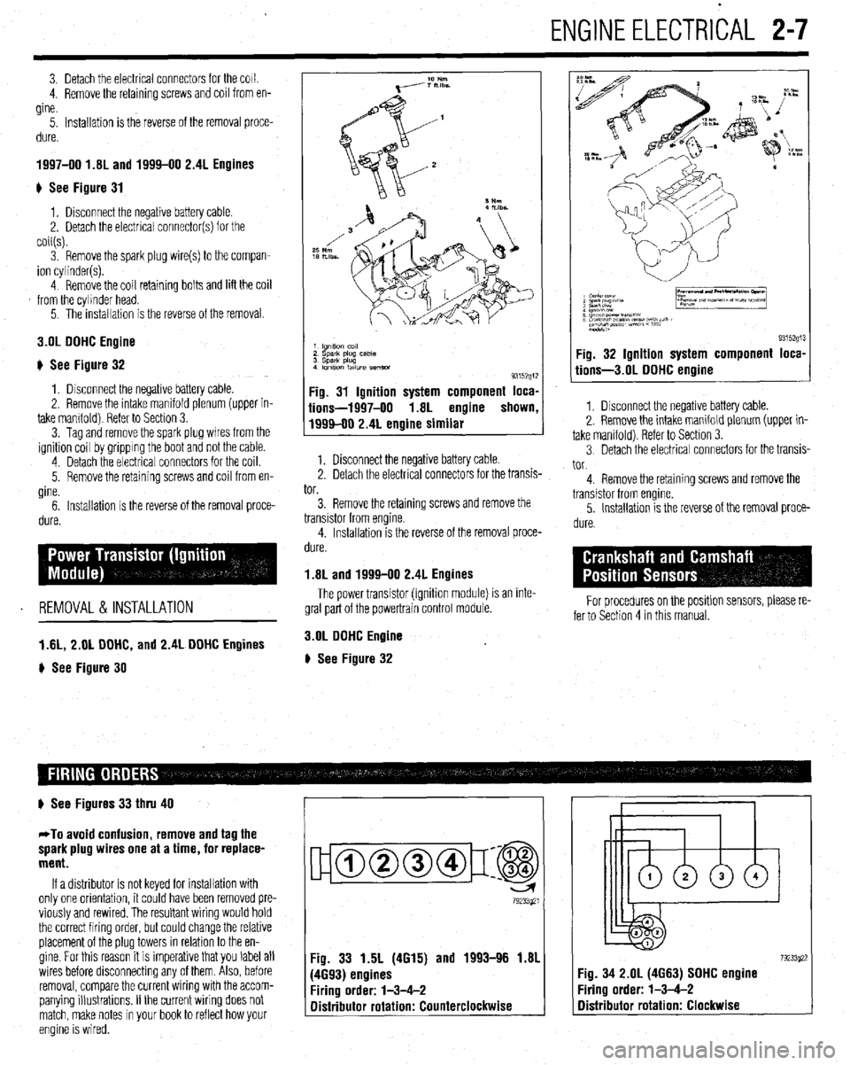
3. Detach the electrical connectors for the COIL
4. Remove the retaining screws and coil from en-
gine.
5. Installation is the reverse of the removal proce-
dure.
1997-00 1.81 and 1994-00 2.4L Engines
) See Figure 31
1, Disconnect the negative battery cable.
2. Detach the electrical connector(s) for the
coil(s).
3. Remove the spark plug wire(s) to the compan-
ion cylinder(s).
4 Remove the coil retaining bolts and lift the coil
from the cylinder head.
5. The installation is the reverse of the removal.
3.OL DOHC Engine
# See Figure 32
1, Disconnect the negative battery cable.
2. Remove the intake manifold plenum (upper in-
take mamfold) Refer to Section 3.
3. Tag and remove the spark plug wires from the
ignition coil by gripping the boot and not the cable.
4 Detach the electrical connectors for the coil.
5. Remove the retaining screws and coil from en-
gine.
6. Installation is the reverse of the removal proce-
dure.
REMOVAL &INSTALLATION
1 AL, 2.01 DOHC, and 2.4L DOHC Engines
) See Figure 30
1 lgnltlo” co,,
2 sparlt plug case
3 Spark plug
4 Imltlon fatlure semm
93152g1:
Fig. 31 Ignition system component loca,
iions-1997-00 1.8L engine shown
1999-00 2.4L engine similar
1. Disconnect the negative battery cable.
2. Detach the electrical connectors for the transis-
tor.
3. Remove the retaining screws and remove the
transistor from engine.
4. Installation is the reverse of the removal proce-
dure.
1.8L and 1999-00 2.4L Engines
The power transistor (ignition module) is an inte-
gral part of the powertrain control module.
3.OL DOHC Engine
# See Figure 32
9315291 Fig. 32 Ignition system component loca,
tions-3.01 DOHC engine
1. Disconnect the negative battery cable.
2. Remove the intake manifold plenum (upper in-
take manifold). Refer to Section 3.
3 Detach the electrical connectors for the transis-
tor.
4. Remove the retaining screws and remove the
transistor from engine.
5. Installation is the reverse of the removal proce-
dure.
For procedures on the positlon sensors, please re-
fer to Section 4 in this manual.
# See Figures 33 thru 40
*To avoid confusion, remove and tag the
spark plug wires one at a time, for replace-
ment.
If a distributor is not keyed for installation with
only one orientation, it could have been removed pre-
viously and rewired. The resultant wiring would hold
the correct firing order, but could change the relative
placement of the plug towers in relation to the en-
gine. For this reason it is imperative that you label all
wires before disconnecting any of them. Also, before
removal, compare the current wiring with the accom-
panying illustrations. If the current wiring does not
match, make notes in your book to reflect how your
engine is wired.
ujamm-p:@
79233921
Fig. 33 1.5L (4615) and 1993-96 1.81
(4693) engines
Firing order: l-3-4-2
Distributor rotation: Counterclockwise 7923392: :ig. 34 2.OL (4663) SOHC engine
‘iring order: l-3-4-2
Distributor rotation: Clockwise
Page 58 of 408
ENGINE ELECTRICAL 2-11
l.unVeMlil(GSflWtWJ
2.Gwwator harness con- connectk,,,
3. Engme OS, level d,pst,&
4 Generator
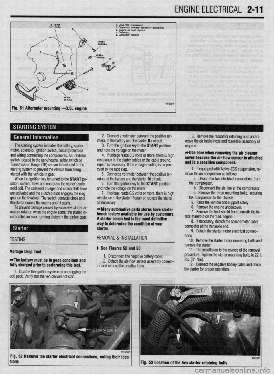
Fig. 51 Alternator mounting -3.51 engine
The starting system includes the battery, starter
motor, solenoid, ignition switch, circuit protection
and wiring connecting the components. An inhibitor
switch located in the park/neutral safety switch or
Transmission Range (TR) sensor is included in the
starting system to prevent the vehicle from being
started with the vehicle in gear.
When the ignition key is turned to the START po-
sition, current flows and energizes the starters sole-
noid coil. The solenoid plunger and clutch shift lever
are activated and the clutch pinion engages the ring
gear on the flywheel. The switch contacts close and
the starter cranks the engine until it starts.
To prevent damage caused by excessive starter ar-
mature rotation when the engine starts, the starter in-
corporates an over-running clutch in the pinion gear. 2. Connect a voltmeter between the positive ter-
minal of the battery and the starter B+ circuit.
3. Turn the ignition key to the START position
and note the voltage on the meter.
4. If voltage reads 0.5 volts or more, there is high
resistance in the starter cables or the cable ground,
repair as necessary. If the voltage reading is ok pro-
teed to the next step.
5. Connect a voltmeter between the positive ter-
minal of the battery and the starter M circuit,
6. Turn the ignition key to the START position
and note the voltage on the meter.
7. If voltage reads 0.5 volts or more, there is high
resistance in the starter. Repair or replace the starter
as necessary.
*Many automotive parts stores have starter
bench testers available for use by customers.
A starter bench test is the most definitive
way to determine the condition of your
starter. 3. Remove the resonator retaining nuts and re-
move the air intake hose and resonator assembly as
required.
rllse care when removing the air cleaner
cover because the air-flow sensor is attached
and is a sensitive component.
4. If equipped with Active-ECS suspension, re-
move the air compressor as follows:
a. Detach the two electrical connectors, from
the compressor.
b. Disconnect the air line at the compressor.
c. Remove the three mounting bolts, securing
the compressor to the chassis.
5. Raise the vehicle and support safely.
6. Remove the engine undercover.
7. Remove the heat shield from beneath the in-
take manifold on the 1.5L engine.
8. If necessary, detach the speedometer cable
connector at the transaxle end.
9. Detach the starter motor electrical connac-
TESTING
Voltage Drop Test
*The battery must be in good condition and
fully charged prior to performing this test. REMOVAL&INSTALLATION
# See Figures 52 and 53
1. Disconnect the negative battery cable.
2. Detach the air-flow sensor assembly connec-
tor and remove the breather hose.
1. Disable the ignition system by unplugging the
coil pack. Verify that the vehicle will not start. tions.
10. Remove the starter motor mounting bolts and
remove the starter.
11. The installation is the reverse of the removal
procedure. Tighten the starter mounting bolts to 22 ft.
Ibs. (31 Nm).
12. Connect the negative battery cable and check
the starter for proper operation.
9315zp19 Fig. 53 Location of the two starter retaining bolts
Page 97 of 408
3-36 ENGINEANDENGINEOVERHAUL
The EPA warns that urolonaed contact with
used engine oil may cause”a number of skin
disorders, including cancer! You should
make every effort to minimize your exposure
to
used engine oil. Protective gloves should
be worn when changing the oil. Wash your
hands and any other exposed skin areas as
soon as possible after exposure to
used en-
gine oil. Soap and water, or waterless hand
cleaner should be used.
4. Remove the solash shield from the wheel
93153p65 93153p60 well.
5. Remove the oil filter adapter.
6. Remove the lower and upper oil pans.
7. Remove the lower baffle, oil pump pick-up
and upper baffle.
8. Remove the oil pump case mounting bolts
and the oil pump case.
9. Remove the oil pump gear cover.
10. Make matchmarks on the oil pump rotors be-
fore removing them.
,,. r.-- -IL- -.( -L.11---‘I --. IL- -.I _ --
nemove me cranksnarr sear rrom me 011 pump
case.
To instell:
12. Install a new crankshaft seal in the oil pump
cover.
13. Apply engine oil to the rotors, then align the
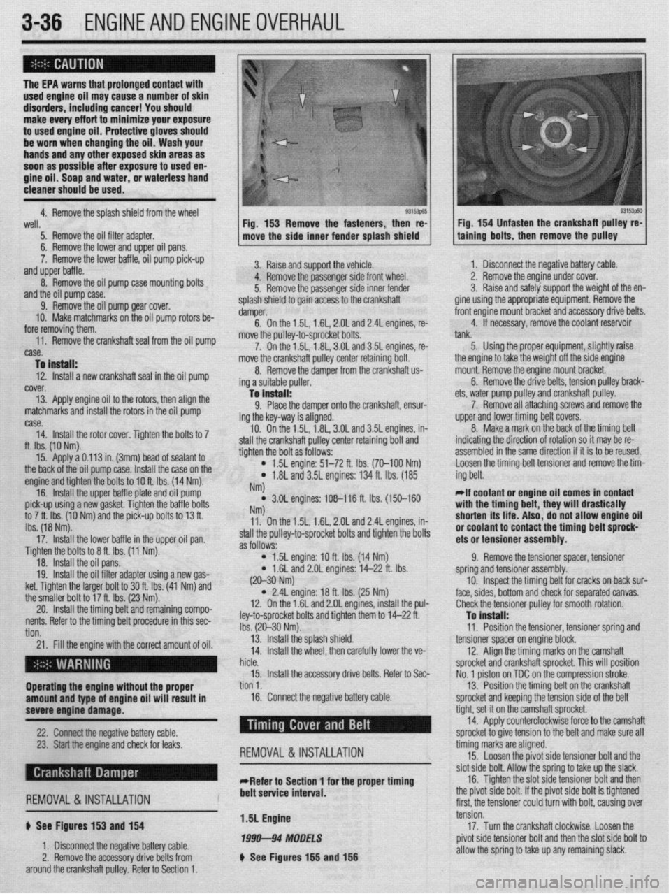
matchmarks and install the rotors in the oil pump Fig. 153 Remove the fasteners, then re-
move the side inner fender splash shield
3. Raise and support the vehicle.
4. Remove the passenger side front wheel.
5. Remove the passenger side inner fender
splash shield to gain access to the crankshaft
damper.
6. On the 1.5L, 1.6L, 2.OL and 2.4L engines, re-
move the oullev-to-sorocket bolts.
7. On thei .5L, i .8L, 3.OL and 3.5L engines, re-
move the crankshaft pulley center retaining bolt.
8. Remove the damper from the crankshaft us
ing a suitable puller.
-la install:
9. Place the damper onto the crankshaft, ensur-
ing the key-way is aligned.
10. On the 1.5L, 1.8L, 3.OL and 3.5L engines, in-
e crankshaft pulley center retaining bolt and
the bolt as follows: Fig. 154 Unfasten the crankshaft pulley re-
talning bolts, then remove the pulley
case.
14. Install the rotor cover. Tighten the bolts to 7
ft. Ibs. (10 Nm).
15. Apply a 0.113 in. (3mm) bead of sealant to
the back of the oil pump case. I[ -‘-‘I IL -~-- IL-
nsrall me ca
se on me engine and tighten the bolts to IOft Ihc 11 ,,, -. , .4 Nm).
16. Install the upper baffle r tlal te and oil pump
pick-up using a new gasket. Tic fhtti,, ,,lG va,,,ti ““a,., an tha hafflc, hnltc to 7 ft. Ibs. (10 Nm) and the pit k-up bolts to 13 ft.
Ibs. (18 Nm).
17. Install the lower baffle in the upper oil pan.
Tighten the bolts to 8 ft. Ibs. (11 Nm).
18. Install the oil pans.
19. Install the oil filter adapter using a new gas-
ket. Tighten the larger bolt to 30 ft. Ibs. (41 Nm) and
the smaller bolt to 1’ u ‘L- Inn ‘I--’ stall thl
tighten
4
) 1.5L engine: 51-72 ft. Ibs. (70-100 Nm)
l 1.8L and 3.5L engines: 134 ft. Ibs. (185
NM
l 3.OL engines: 108-116 ft. lbs. (150-160 NW 11. On the 1.5L, 1.6L, 2.OL and 2.4L engines, in-
stall the pulley-to-sprocket bolts and tighten the bolts
as follows:
l 1.5L engine: 10 ft. Ibs. (14 Nm)
* 1.6L and 2.OL engines: 14-22 ft. Ibs. 1. Disconnect the negative battery cable.
2. Remove the engine under cover.
3. Raise and safely support the weight of the en-
gine using the appropriate equipment. Remove the
front engine mount bracket and accessory drive belts.
4. If necessary, remove the coolant reservoir
tank.
5. Using the proper equipment, slightly raise
ets, water pump pulley
7. Remove all attr
upper and lower timin{
8. Make a mark o
indicating the directior
assembled in the same the engine to take the weight off the side engine
mount. Remove the engine mount bracket.
6. Remove the drive belts, tension pulley brack-
and crankshaft pulley.
aching screws and remove the
J belt covers.
n the back of the timing belt
I of rotation so it may be re-
! direction if it is to be reused.
tensioner and remove the tim-
Loosen the timing belt
ing belt.
*If coolant or engine oil comes in contact
with the timing bplt thaw will r(mcti~~llv Wll L, .,,s,, n,,, u,uu.,vu,,,
shorten its life. A ,IS o, do not allow engine oil
#.I nn..lr”* In rind In,
“I IruuI(IIIL Lu Irulll&t the timing belt sprock-
ets or tensioner assembly.
9. Remove the tensioner spacer, tensioner
spring and tensioner assembly.
cracks on back sur-
;eoarated canvas.
20. Install the tilllIllY uljllOllu IclllallllllY ~ullIPV-
:
nents. Refer to the timing belt procedure in this sec-
: tion.
21. Fill the engine with the correct amount of oil.
I . (20-30 Nm)
l 2.4L engine: 18 ft. Ibs. (25 Nm)
12. On the 1.6L and 2.OL engines, install the pul-
ley-to-sprocket bolts and tighten them to 14-22 ft.
Ibs. (20-30 Nm).
13. Install the splash shield.
14. Install the wheel, then carefully lower the ve- 10. Inspect the timing belt for I
face, sides, bottom and check for ! (
Check the tensioner pulley for smooth rotation.
To install:
11. Position the tensioner, tensioner spring and
tensioner spacer on engine block.
12. Align the timing marks on the camshaft
ft sprocket. This will position
tn the comoression stroke.
I hicle.
sprocket and cranksha
15. Install the accessory drive belts. Refer to Sec-
No. 1 piston on TDC o
Operating the engine without the proper tion 1.
13. Position the timing belt on the crankshaft
amount and type of engine oil will result in 16. Connect the negative battery cable.
sprocket and keeping the tension side of the bolt
severe engine damage.
-
22. -s
Chrmxt the nenntive h;lttm cnhle --, , I” ,.-J XL.._ I -..-., --I.-.
23. Start the engine and check for leaks.
REMOVAL &INSTALLATION
tight, set it on the cam, shaft sprocket.
14. Apply counterc Yockwise force to the camshaft
snrnckd tn nive tensin In -r .__.._. ._ J..- ._ - _ to the belt and make sure all
timing marks are aligned.
15. Loosen the pivot side tensioner bolt and the
clnt
&In hnlt Allnur thn rnrinn tn tdm III-I thn slack, cl then , d I, I’ r),“I 44”” ““IL. “ll”sl LllU .y”“yj L” L”I\U Low Ul” L .-Refer to Section 1 for the proper timing 16. Tighten the slot side tensioner bolt ark
., , , , ,, ,, ,, , , , , ,, . ,, ,~
REMOVAL &INSTALLATION
6 See Figures 153 and 154
1. Disconnect the negative battery cable.
2. Remove the accessory drive belts from
around the crankshaft pulley. Refer to Section 1. belt service interval.
1.5L Engine
1999-94 MODELS
b See Figures 155 and 156 me p~vor sloe DOI~. IT me p~vor sloe OOII
IS ogntened
first, the tensioner could turn with bolt, causing over
tension.
17. Turn the crankshaft clockwise. Loosen the
pivot side tensioner bolt and then the slot side bolt to
allow the spring to take up any remaining slack.
Page 128 of 408
ENGINEANDENGINEOVERHAUL 3-67
CONNECTING ROD
You should have the connecting rod checked for
StraiQhtness at a machine shop. If the connecting rod
is bent, it will unevenly wear the bearing and piston,
as well as place greater stress on these components.
Any bent or twisted connecting rods must be re-
placed. If the rods are straight and the wrist pin clear-
ance is within specifications, then only the bearing
end of the rod need be checked. Place the connecting
rod into a vice, with the bearing inserts in place, in-
stall the cap to the rod and torque the fasteners to
specifications. Use a telescoping gauge and carefully
measure the inside diameter of the bearings. Com-
pare this reading to the rods original crankshaft jour-
nal diameter measurement. The difference is the oil
clearance. If the oil clearance is not within specifica-
tions, install new bearings in the rod and take another
.
specifica- L
need to
shop as the pistons must be installed in the con measurement. it the Clearance is still out of :
tions, and the crankshaft is not, the rod will
be reconditioned by a machine shop.
*You can also use Plastigage’
@to check the
bearing clearances. The assen- . ...= - _______
Mm sectinn has complete instructions on its use.
Camshaft
Inspect the camshaft and lifters/followers as de
scribed earlier in this section.
Bearings
All of the enaine bearinos should be visuallv in-
~~~ I~ .- - -- ..-_-..,
spected for we; and/or damage. The bearing should
look evenly worn all around with no deep scores or
pits. If the bearing is severely worn, scored, pitted or
heat blued, then the bearing, and the components
that use it, should be brought to a machine shop for
block. ,ect
relationshipto the rod or engine damage can occur,
Pistons and Connecting Rods
I
b See Fiaute 264 --- --*------
Only pistons with the wrist pin retained by C-clips
are serviceable by the home-mechanic. Press fit pis-
tons require special presses and/or heaters to re- I”
rr
rove/install the connecting rod and should only be
PC srformed by a machine shop.
All pistons will have a mark indicating the direc-
tir 9n to the front of the engine and the must be in-
stalled into the engine in that manner. Usually it is a
notch or arrow on the top of the piston, or it may be
the letter F cast or stamped into the piston.
ASEtiBlY
1
crankshaft. Replace any freeze or oil galley plugs
which were removed during disassembly.
Crankshaft
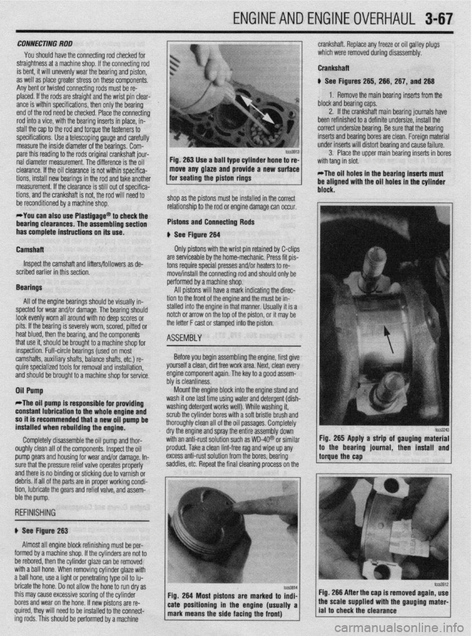
u See Figures 265, 266, 267, and 266
1. Remove the main bearing inserts from the
block and bearing caps.
2. If the crankshaft main bearing journals have
been refinished to a definite undersize, install the
correct undersize bearina. Be sure that the bearina
inserts and bearing bores are clean. Foreign mateiial
under inserts will distort bearinq and cause failure.
3. Place the upper main bearing inserts in bores
*The oil holes in the bearing inserts must
be aligned with the oil holes in the cylinder
. . .
inspection. Full-circle bearings (used on most
camshafts, auxiliary shafts, balance shafts, etc.) re-
quire specialized tools for removal and installation, ’
and should be brought to a machine shop for service.
Oil Pump Before you begin assembling the engine, first give
yourself a clean, dirt free work area. Next, clean every
engine component again. The key to a QOOd assem-
hhr io da~nlinmw “‘I Ia ~rGiOllll,lc7.Ja. Mount the engine block into the engine stand and
II
*The oil pump is responsible fo
r providing wasn It one last time usmg water and detergent (dish-
unrhinn rldarnant ~nrirc well), While washing it, with a soft bristle brush and
: oil oassaoes. Comoletelv constant lubrication to the whole engine and 1ILl.M 0, ,y “GSGl ycx II ““1 n
so it is recommended that a new oil pump be scrub the cylinder bore:
installed when rebuilding the engine. thoroughly clean all oft
dry the engine and spra
Completely disassemble the oil pump and thor- with an anti-rust solutio
oughly clean all of the components. Inspect the oil
pro
pump Qears and housing for wear and/or damage. In- exe
sure that the pressure relief valve operates properly sac
and there is no binding or sticking due to varnish or
debris. If all of the parts are in proper working condi-
tion, lubricate the gears and relief valve, and assem-
r
j ht
y the entire assembly down’
in such as WD-4Q@ or similar Fig. 265 Apply a strip of gauging material
Iduct. Take a clean lint-free rag and wipe up any
less anti-rust solution from the bores, bearing
Idles, etc. Repeat the final cleaning process on the !torguethe~~p * ,’ / to the bearmg lournal, then mstall and
ble the pump.
REFINISHING
# See Figure 263
Almost all engine block refinishing must be per-
I
IUIIII~U uy a macnme snap. ir me cynnoers are nor ro
be rebored, then the cylinder glaze can be removed
with a ball hone. When removing cylinder glaze with
a ball hone, use a light or penetrating type oil to Iu-
bricate the hone. Do not allow the hone to run dry as
this may cause excessive scoring of the cylinder
bores and wear on the hone. If new pistons are re-
quired, they will need to be installed to the connect-
ing rods. This should be oerformed bv a machine Fig. 266 After the cap is removed again, use