1900 MITSUBISHI DIAMANTE wiper blades
[x] Cancel search: wiper bladesPage 28 of 408
GENERALINFORMATIONAND MAlNTENANdE 1-29
i
*Bug screens which are mounted in front of
the condenser (unless they are original
equipment) are regarded as obstructtons.
l The condensation drain tube expels any water
which accumulates on the bottom of the evaporator
housing into the engine compartment. If this tube is
obstructed, the air conditioning performance can be
restricted and condensation buildup can spill over
onto the vehicle’s floor.
l Make sure the air passage selection lever is
operating correctly. Start the engine and warm it to
normal operating temperature, then make sure the
temperature selection lever is operating correctly.
-w
~1 ELEMENT(REFILL)CARE& REPLACEMENT
SYSTEM INSPECTION
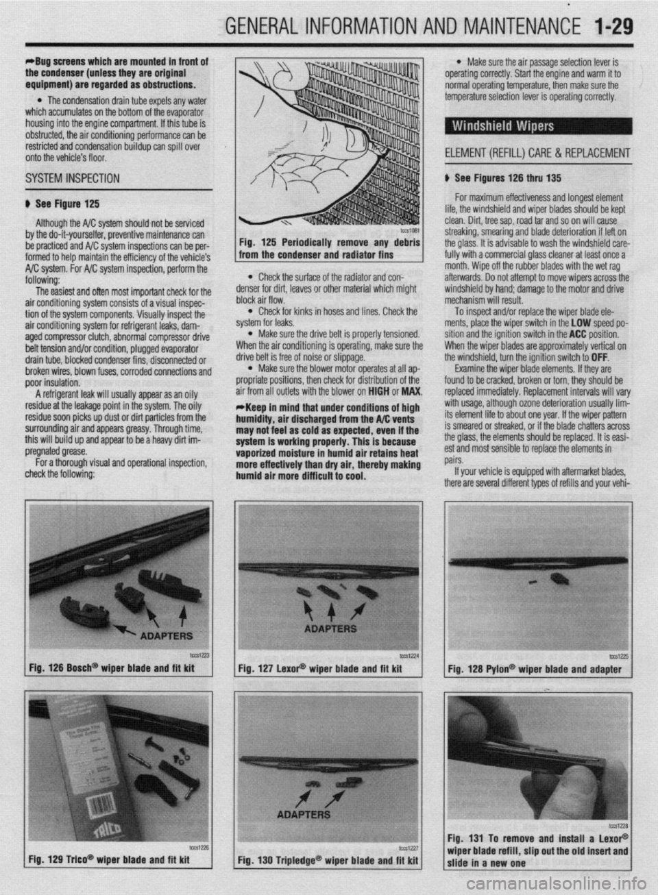
b See Figure 125 b See Figures 126 thru 135
For maximum effectiveness and longest element
Although the A/C system should not be serviced
by the do-it-yourselfer, preventive maintenance can
be practiced and A/C system inspections can be per-
formed to help maintain the efficiency of the vehicle’s
A/C system. For A/C system inspection, perform the
following:
The easiest and often most important check for the
air conditioning system consists of a visual inspec-
tion of the system components. Visually inspect the
air conditioning system for refrigerant leaks, dam-
aged compressor clutch, abnormal compressor drive
belt tension and/or condition, plugged evaporator
drain tube, blocked condenser fins, disconnected or
broken wires, blown fuses, corroded connections and
poor insulation.
A refrigerant leak will usually appear as an oily
residue at the leakage point in the system. The oily
residue soon picks up dust or dirt particles from the
surrounding air and appears greasy. Through time,
this will build up and appear to be a heavy dirt im-
pregnated grease.
For a thorough visual and operational inspection,
check the following: * Check the surface of the radiator and con-
denser for dirt, leaves or other material which might
block air flow.
l Check for kinks in hoses and lines. Check the
system for leaks.
l Make sure the drive belt is properly tensioned.
When the air conditioning is operating, make sure the
drive belt is free of noise or slippage.
l Make sure the blower motor operates at all ap-
propriate positions, then check for distribution of the
air from all outlets with the blower on HIGH or MAX.
*Keep in mind that under conditions of high
humidity, air discharged from the A/C vents
may not feel as cold as expected, even if the
system is working properly. This is because
vaporized moisture in humid air retains heat
more effectively than dry air, thereby making
humid air more difficult to cool.
lifp thp winrkhi&i nnri winor hlarlP~ shmM hP kmt . ..“. .I.” . . * ““I.. “.” I..” ...r”* “.“““” “, ,““,” “” ,~“r~ clean. Dirt, tree sap, road tar and so on will cause
streaking, smearing and blade deterioration if left on
the glass. It is advisable to wash the windshield care-
fully with a commercial glass cleaner at least once a
month. Wipe off the rubber blades with the wet rag
afterwards. Do not attempt to move wipers across the
windshield by hand; damage to the motor and drive
mechanism will result.
To inspect and/or replace the wiper blade ele-
ments, place the wiper switch in the LOW speed po-
sition and the ignition switch in the ACC position.
When the wiper blades are approximately vertical on
the windshield, turn the ignition switch to OFF.
Examine the wiper blade elements. If they are
found to be cracked, broken or torn, they should be
replaced immediately. Replacement intervals will vary
with usage, although ozone deterioration usually lim-
its element life to about one year. If the wiper pattern
is smeared or streaked, or if the blade chatters across
the glass, the elements should be replaced. It is easi-
est and most sensible to replace the elements in
pairs.
If your vehicle is equipped with aftermarket blades,
there are several different types of refills and your vehi-
tcca-23 Fig. 126 Bosch@ wiper blade and fft kit
Fig. 129 T&o* wioer blade and fit kit tCS1224
lW1Z?5 Fig. 127 LexoP wiper blade and fit kit
Fig. 128 Pylon@ wiper blade and adapter
Fig. 131 To remove and install a LexoP
Fig, 130 Tripledge@ wiper blade and fit kit wiper blade refill, slip out the old insert and
slide in a new one
Page 29 of 408
.
l-30 GENERAL'INFORMATIONAND MAINTENANCE
n Pylon@ inserts, the clip
be removed prior to siidi then the insert can be re
After installing the replacement
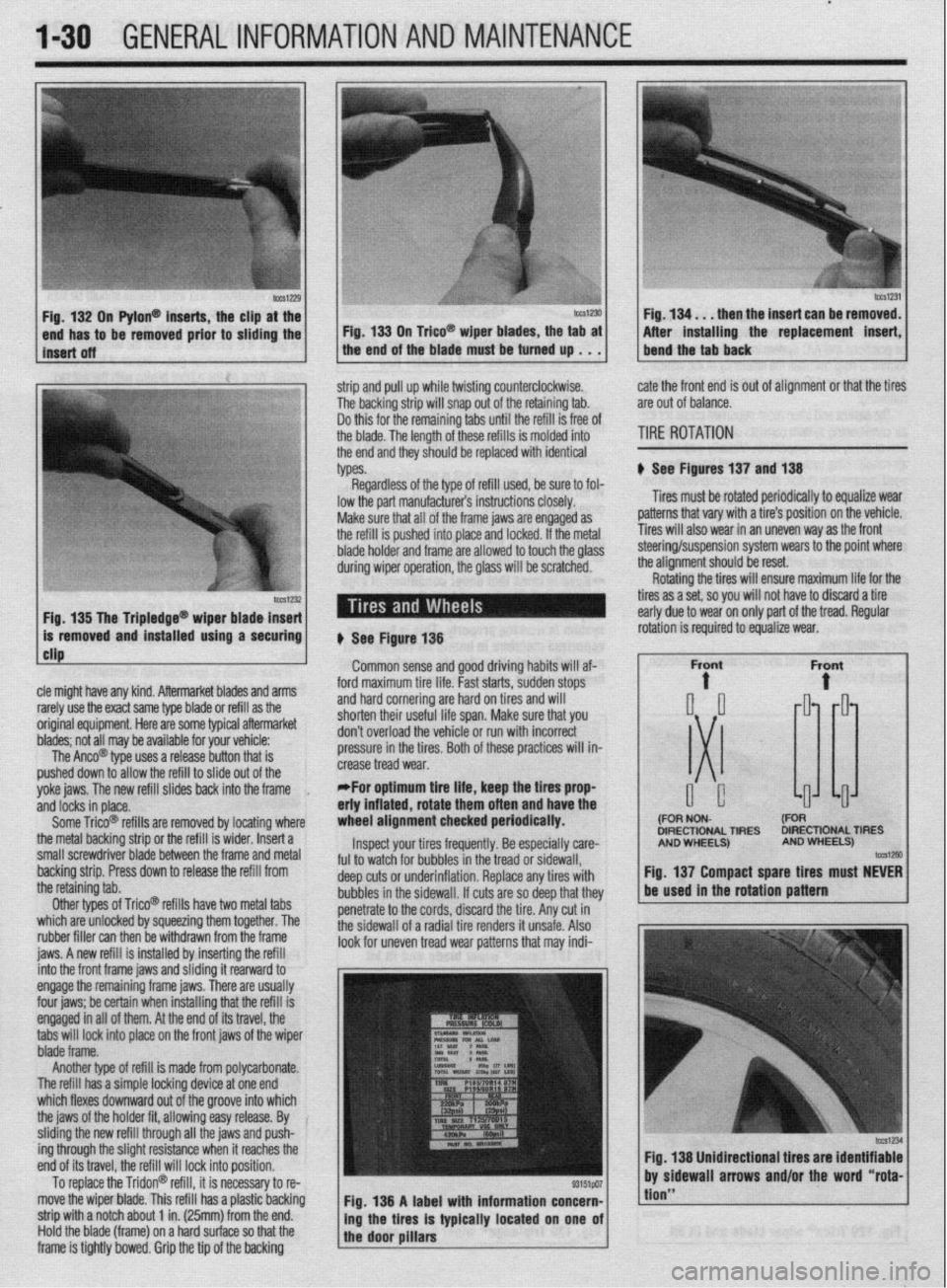
strip and pull up while twisting counterclockwise.
The backing strip will snap out of the retaining tab.
Do this for the remaining tabs until the refill is free of
the blade. The length of these refills is molded into
the end and they should be replaced with identical
types. cate the front end is out of alignment or that the tires
are out of balance.
TIRE ROTATION
# See Figures 137 and 138
Tires must be rotated periodically to equalize wear
patterns that vary with a tire’s position on the vehicle.
Tires will also wear in an uneven way as the front
1 Fin 1% Tha Trinlarlna@
cle might have any kind. Aftermarket blades and arms
rarely use the exact same type blade or refill as the
original equipment. Here are some typiel aftermarket
blades; not all may be available for your vehicle:
The Anco@ type uses a release button that is
pushed down to allow the refill to slide out of the
yoke jaws. The new refill slides back into the frame
,
and locks in place.
Some Trico@ refills are removed by locating where
the metal backing strip or the refill is wider. Insert a
small screwdriver blade between the frame and metal
backing strip. Press down to release the refill from
the retaining tab.
Other types of Trico@’ refills have two metal tabs
which are unlocked by squeezing them together. The
rubber filler can then be withdrawn from the frame
iaws. A new refill is installed bv insertina the refill lowed to touch the olass steering/suspension system wears to the point where
the alianment should be reset.
# See Figure 138
Common sense and good driving habits will af-
ford maximum tire life. Fast starts, sudden stops
and hard cornering are hard on tires and will
shorten their useful life span. Make sure that you
don’t overload the vehicle or run with incorrect
pressure in the tires. Both of these practices will in-
crease tread wear.
*For optimum tire life, keep the fires prop
eriy inflated, rotate them often and have the
wheel alignment checked periodically.
Inspect your tires frequently. Be especially care-
ful to watch for bubbles in the tread or sidewall,
deep cuts or underinflation. Replace any tires with
bubbles in the sidewall. If cuts are so deep that they
penetrate to the cords, discard the tire. Any cut in
the sidewall of a radial tire renders it unsafe. Also
look for uneven tread wear patterns that may indi- Rotating the tires will ensure maximum life for the
tires as a set, so you will not have to discard a tire
early due to wear on only part of the tread. Regular
DIRECTIONAL TIRES DIRECTIONAL TIRES
jnto the front frame jaws and &ding it rearward to
engage the remaining frame jaws. There are usually
four jaws; be certain when installing that the refill is
engaged in all of them. At the end of its travel, the
tabs will lock into place on the front jaws of the wiper
blade frame.
Another type of refill is made from polycarbonate.
The refill has a simple locking device at one end
which flexes downward out of the groove into which
the jaws of the holder fit, allowing easy release. By
sliding the new refill through all the jaws and push-
ing through the slight resistance when it reaches the
end of its travel, the refill will lock into position.
To replace the Tridon@ refill, it is necessary to re-
move the wiper blade. This refill has a plastic backing
strip with a notch about 1 in. (25mm) from the end.
Hold the blade (frame) on a hard surface so that the
frame is tightly bowed. Grip the tip of the backing Fig. 138 A label with information concern-
ing the tires is typically located on one of
the door pillars
tion”
Page 42 of 408
GENERALINFORMATIONAND MAINTENANCE l-43
l Special car washing detergent is the best to
use. Liquid dishwashing detergent can remove wax
and leave the car’s paint unprotected and in addition
some liquid detergents contains abrasives which can
scratch the paint.
l Bird droppings should be removed from the
paintwork as soon as possible, otherwise the finish
may be permanently stained.
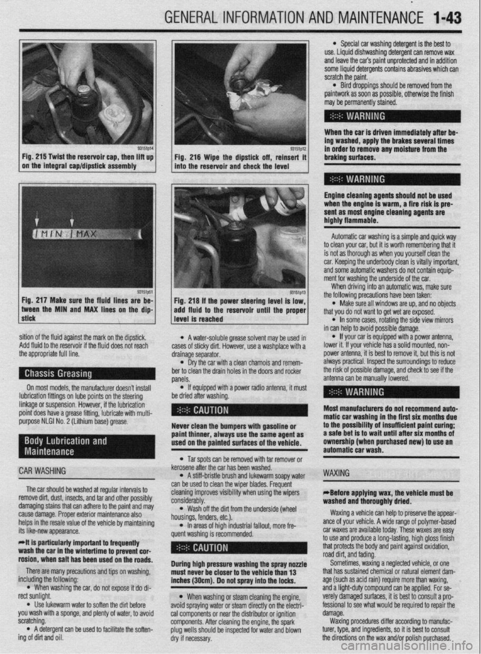
When the car is driven immediately after be-
ing washed, apply the brakes several times
93151p14 93151p12 Fig. 215 Twist the reservoir cap, then lift up
I I
in order to remove any moisture from the
Fig. 216 Wipe the dipstick off, reinsert it braking surfaces.
on the integral cap/dipstick assembly
into the reservoir and check the level
I
Engine cleaning agents should not be used
when the engine is warm, a fire risk is pre-
sent as most engine cleaning agents are
highly flammable.
sition of the fluid against the mark on the dipstick,
Add fluid to the reservoir if the fluid does not reach
the appropriate full line.
On most models, the manufacturer doesn’t install
lubrication fittings on lube points on the steering
linkage or suspension. However, if the lubrication
point does have a grease fitting, lubricate with multi-
purpose NLGI No. 2 (Lithium base) grease.
CAR WASHING
The car should be washed at regular intervals to
remove dirt, dust, insects, and tar and other possibly
damaging stains that can adhere to the paint and may
cause damage. Proper exterior maintenance also
helps in the resale value of the vehicle by maintaining
its like-new appearance.
Mt is particularly important ta frequentiy
wash the car in the wintertime to prevent cor-
rosion, when salt has been used on the roads.
There are many precautions and tips on washing,
including the following:
l When washing the car, do not expose it do di-
rect sunlight.
. Use lukewarm water to soften the dirt before
you wash with a sponge, and plenty of water, to avoid
scratching.
l A detergent can be used to facilitate the soften-
ing of dirt and oil. * A water-soluble grease solvent may be used in
cases of sticky dirt. However, use a washplace with a
drainage separator.
l Dry the car with a clean chamois and remem-
ber to clean the drain holes in the doors and rocker
panels.
l If equipped with a power radio antenna, it must
be dried after washing.
Never clean the bumpers with gasoline or
paint thinner, always use the same agent as
used on the painted surfaces of the vehicle.
l Tar spots can be removed with tar remover or
kerosene after the car has been washed.
l A stiff-bristle brush and lukewarm soapy water
can be used to clean the wiper blades. Frequent
cleaning improves visibility when using the wipers
considerably.
l Wash off the did from the underside (wheel
housings, fenders, etc.).
l In areas of high industrial fallout, more fre-
quent washing is recommended.
During high pressure washing the spray nonle
must never be closer to the vehicle than 13
inches (30cm). Do not spray into the locks.
l When washing or steam cleaning the engine,
avoid spraying water or steam directly on the electri-
cal components or near the distributor or ignition
components. After cleaning the engine, the spark
plug wells should be inspected for water and blown
dry if necessary. Automatic car washing is a simple and quick way
to clean your car, but it is worth remembering that it
is not as thorough as when you yourself clean the
car. Keeping the underbody clean is vitally important,
and some automatic washers do not contain equip-
ment for washing the underside of the car.
When driving into an automatic was, make sure
the following precautions have been taken:
l Make sure all windows are up, and no objects
that you do not want to get wet are exposed.
l In some cases, rotating the side view mirrors
in can help to avoid possible damage.
l If your car is equipped with a power antenna,
lower it. If your vehicle has a solid mounted, non-
power antenna, it is best to remove it, but this is not
always practical. Inspect the surroundings to reduce
the risk of possible damage, and check to see if the
antenna can be manually lowered.
Most manufacturers do not recommend auto-
matic car washing in the first six months due
to the possibility of insufficient paint curing;
a safe bet is to wait until after six months of
ownership (when purchased new) to use an
automatic car wash.
WAXING
eBefore applying wax, the vehicle must be
washed and thoroughly dried.
Waxing a vehicle can help to preserve the appear-
ante of your vehicle. A wide range of polymer-based
car waxes are available today. These waxes are easy
to use and produce a long-lasting, high gloss finish
that protects the body and paint against oxidation,
road dirt, and fading.
Sometimes, waxing a neglected vehicle, or one
that has sustained chemical or natural element dam-
age (such as acid rain) require more than waxing,
and a light-duty compound can be applied. For se-
verely damaged surfaces, it is best to consult a pro-
fessional to see what would be required to repair the
damage.
Waxing procedures differ according to manufac-
turer, type, and ingredients, so it is best to consult
the directions on the wax and/or polish purchased.
Page 219 of 408
646 CHASSIS ELECTRICAL
To install: 2. Remove the rear wiper arm by removing the 2. Remove the windshield wiper arms by un-
3. Install the wiper blade and arm assemblies, cap nut cover, unscrewing the cap nut and lifting the screwing the cap nuts and lifting the arms from the
Tighten the retaining nuts to 7-12 ft. Ibs. (10-16 arm from the linkage post. linkage posts.
Nm). 3. Remove the large interior trim panel. Use a 3. Remove the front garnish panel.
4. Note that the drivers side wiper arm should be plastic trim stick to unhook the trim clips of the lift- 4. Remove the air inlet trim pieces.
marked D or Dr and the passenger’s side wiper arm gate trim. There will be a row of metal liftgate clips 5. Remove the hole cover.
should be marked A or As. The identification marks across the top. There will be 2 rows of trim clips that 6. Remove the wiper motor by loosening the
should be located at the base of the arm, near the retain the rest of the panel. mounting bolts, removing the motor assembly, then
pivot. Install the arms so the blades are 1 inch from 4. Disconnect the electrical harness at the wiper disconnecting the linkage.
the garnish molding when parked. motor. Remove the rear wiper assembly. Do not
5. Connect the negative battery cable and check loosen the grommet for the wiper post. *The installation angle of the crank arm and
the wiper system for proper operation. To install: motor has been factory set; do not remove
5. Install the motor and grommet. Mount the them unless it is necessary to do so. If they
grommet so the arrow on the grommet is pointing must be removed, remove them only after
downward. marking their mounting positions.
REMOVAL&INSTALLATION 6. Install the wiper arm. To install:
7. Connect the negative battery cable and check 7. Install the windshield wiper motor and con-
rear wiper system for proper operation. nect the linkage.
1999-92 Mirage 8. If operation is satisfactory, fit the tabs on the 8. Reinstall all trim pieces.
upper part of the liftgate trim into the liftgate clips 9. Reinstall the wiper blades. Note that the dri-
FRONT ‘~ and secure the liftgate trim. ver’s side wiper arm should be marked D or Dr and
the passengers side wiper arm should be marked A
1. Disconnect the negative battery cable. 1993-00 Mirage or As. The identification marks should be located at
2. Remove the windshield wiper arms by un-
1. Disconnect the negative battery cable. the base of the arm, near the pivot. Install the arms so
screwing the cap nuts and lifting the arms from the
linkage posts. 2. Remove the windshield wiper arms by un- the blades are 1 inch from the garnish molding when
screwing the cap nuts and lifting the arms from the . parked.
3. Remove the front deck garnish panel.
linkage posts, 10. Connect the negative battery cable and check
4. Remove both windshield holders.
3. Remove the front deck garnish panel. the wiper system for proper operation.
5: Remove the clips that hold the deck cover. If
they are the pin type, they may be removed using the 4. Remove both windshield holders.
5. Remove the clips that hold the deck cover. If Diamante and 199440 Galant
following procedure:
a. Remove the clip by pressing down on the they are the pin type, they may be removed using the
, following procedure. FRONT
center pin with a suitable blunt pointed tool.
Press down a little more than l/r6 in. (2mm). a. Remove the clip by pressing down on the
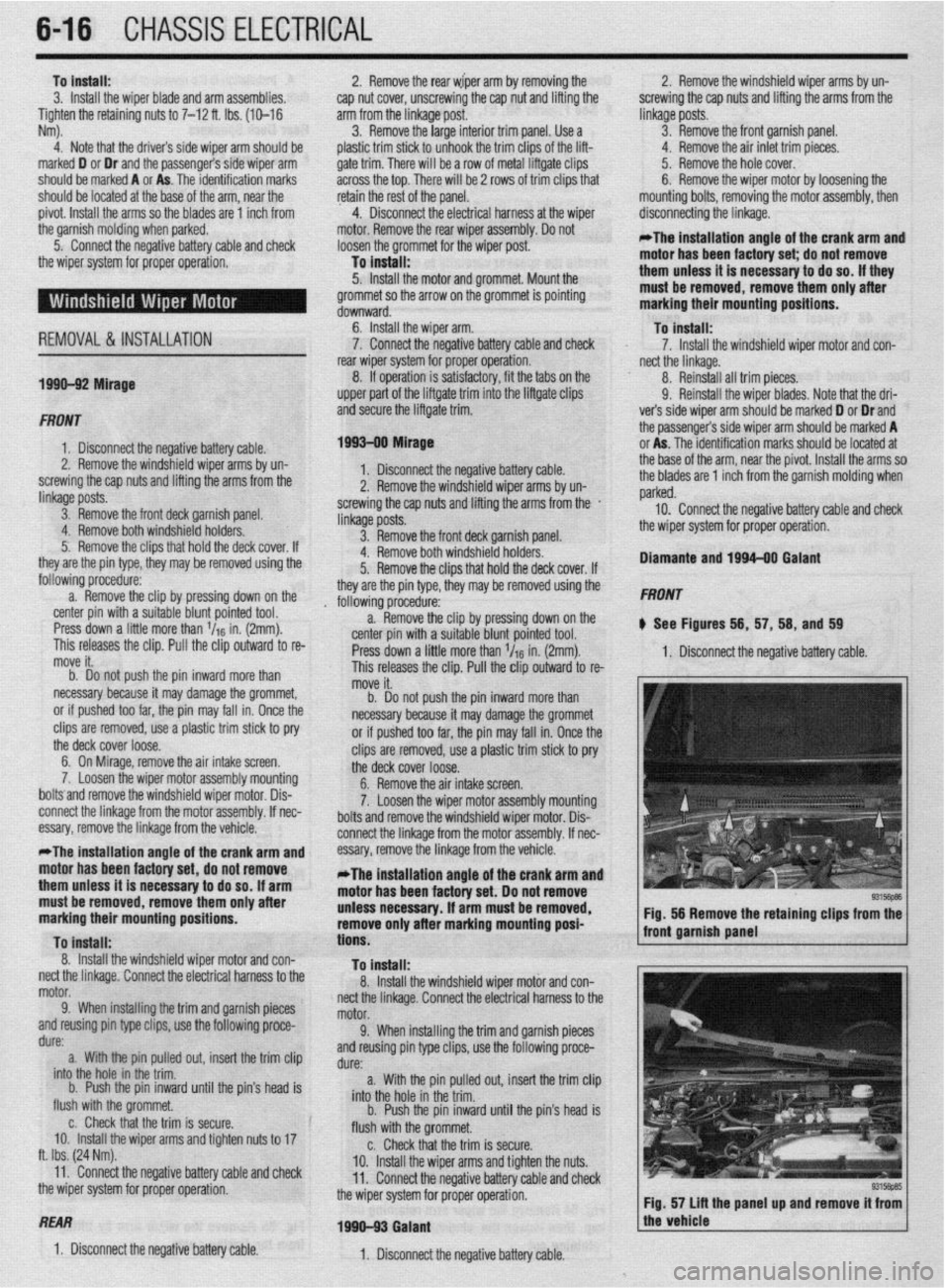
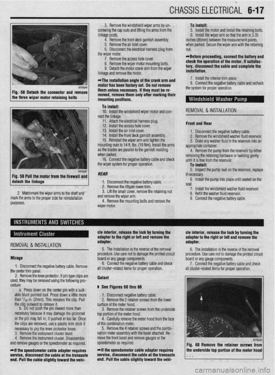
b See Figures 56, 57, 58, and 59
This releases the clip. Pull the clip outward to re- center pin with a suitable blunt pointed tool.
move it. Press down a little more than l/r6 in. (2mm). 1. Disconnect the negative battery cable.
b. Do not push the pin inward more than This releases the clip. Pull the clip outward to re-
necessary because it may damage the grommet, move it.
or if pushed too far, the pin may fall in. Once the b. Do not push the pin inward more than
clips are removed, use a plastic trim stick to pry necessary because it may damage the grommet
the deck cover loose. or if pushed too far, the pin may fall in. Once the
6. On Mirage, remove the air intake screen. clips are removed, use a plastic trim stick to pry
7, Loosen the wiper motor assembly mounting the deck cover loose.
boltsand remove the windshield wiper motor. Dis- 6. Remove the air intake screen.
connect the linkage from the motor assembly. If nec- 7. Loosen the wiper motor assembly mounting
essary, remove the linkage from the vehicle. bolts and remove the windshield wiper motor. Dis-
connect the linkaae from the motor assemblv. If nec-
*The installation angle of the crank arm and
motor has been factory set, do not remove
them unless it is necessary to do so. If arm
must be removed, remove them only after
marking their mounting positions.
To Install:
8. Install the windshield wiper motor and con-
nect the linkage. Connect the electrical harness to the
motor.
9. When installing the trim and garnish pieces
and reusing pin type clips, use the following proce-
dure:
a. With the pin pulled out, insert the trim clip
into the hole in the trim.
b. Push the pin inward until the pin’s head is
flush with the grommet.
c. Check that the trim is secure.
IO. Install the wiper arms and tighten nuts to 17
ft. Ibs. (24 Nm).
11. Connect the negative battery cable and check
the wiper
systerr I-- -_-^-_ -----,:-- II 101 plupel uperatlull.
essary, remove the linkage from the vehicle.-
*The installation angle of the crank arm and
motor has been factory set. Do not remove
unless necessary. If arm must be removed,
remove only after marking mounting posi-
tions.
To install:
8. Install the windshield wiper motor and con-
nect the linkage. Connect the electrical harness to the
motor.
9. When installing the trim and garnish pieces
and reusing pin type clips, use the following proce-
dure:
a. With the pin pulled out, insert the trim clip
into the hole in the trim.
b. Push the pin inward until the pin’s head is
flush with the grommet.
c. Check that the trim is secure.
10. Install the wiper arms and tighten the nuts.
11. Connect the negative battery cable and check
the wiper system for proper operation. Fig. 56 Remove the retaining clips from the
front garnish panel
REAR
1990-93 Galant
1. Disconnect the negative battery cable.
1. Disconnect the negative battery cable.
Fig. 57 lift the panel up and remove it from 1
the vehicle
I
Page 220 of 408
CHASSIS ELECTRICAL 647
3. Remove the windshield wiper arms by un-
screwing the cap nuts and lifting the arms from the
linkage posts.
4. Remove the front deck garnish assembly.
Iver.
xl harness plug from
,I6 #-n\,LIr 5. Remove the air inlet c(
6. Disconnect the electric
the wiper motor.
7. Remove the access ho,, LIVIGil. To install:
5. Install the motor and install the retaining bolts.
6. Install the wiper arm so that the arm is 3.35
inches (85mm) between the measurement points,
when parked. Secure the wiper arm with the retaining
nut.
*Before proceeding, connect the battery and
8. Remove the wiper motor mounting bolts.
9. Detach the motor crank arm from the wiper
linkane and remnve the mntnr
motor has been factory set. Do not remove
them unless necessary. if they must be re-
moved, remove them only after marking their
mounting positions. check the operation of the motor. if satisfae-
tory, disconnect the cable and complete the
installation.
o. WIIIIW LIE Il~&WVt: vatreryoable and recheck
the system for proper operation.
..-
a- - ‘- _ _ _ . _ _ _
*The installation angle of the crank arm and 7. Install the interior trim piece
n II ^_^^^ IAL- -^I-I:..- L-AL--
To install:
10. Install the windshield wiper motor and con-
REMOVAL&INSTALLATION nect the linkage.
I 14. Install the front deck garnish assembly. I. YIV”“I1IIYVL VI” “UyuL’.” “UL’“‘, UUUIU. 2. Remove the windshield washer fluid resarvnir
’ 11. Attach the electrical harness plug.
12. Install the access hole cover.
13. Install the air inlet cover.
15. Reinstall the wiper arm and tighten the
mounting nuts to 14 ft. Ibs. (19 Nm). Install the arms
so the blades are parallel to the garnish molding -
Front and Rear
1 nivnnnprt the nonatiua haltorv rahlo
3. Drain any washer fluid in the reservoir into an
appropriate container.
4.
I when parked. Remove the pump from the reservoir by either
16. Connect the neaative batterv cable and check removing the retaining hardware or twisting gently
tlntil it is frpp frnm thP rosorvnir the wiper system for proper operation.
lo Install:
5. Inspect the pump seal on the reservoir, replace
/ de&h the linkage Fig 59 Pull the motor from the firewaii and
“‘%‘y 1 ““I”“,,,,,, the if necessary.
1 1 Disconn& thP rwnativo hatton/ rahlm 6. Install the pump into place until seated on the .I,” ~‘“p.L’,” YULL”‘, -YI”. liftgate lower trim. seal.
3: Lift the smatr CUVBI, I~IIIUV~ tilt: lfAdllllll~ IIUL II --. .-- -^- ^..^ .L^ -_,_:..:-- -.A 7. Install the windshield washer fluid reservoir. 2. Matchmark the wirier arms tn the shaft and A Refill thp wxhpr fllk-l rpqprvnir markthe arms to the proper side for reinstallation and remove the wiper arm.
4. Remove the mountina bolts and remove the “. .,“...S .V.” ....“III. ,*..*” IYUY..“m,.
9. Connect the negative battery cable.
REMOVAL&INSTALLATION
tie interior, release the lock by turning the tie interior, release the lock by turning the
adapter to the right or left and remove the adapter to the rigM or left and remove the
adapter. adapter.
5. The installation is the reverse of the removal
6. The installation is the reverse of the removal
Mirage
1. Disconnect the negative battery cable. Remove
the center trim panel. procedure. Use care not to damage the printed circuit procedure. Use care not to damage the printed circuit
board or any gauge components.
board or any gauge components.
6. Connect the negative battery cable and check
7. Connect the negative battery cable and check
all cluster-related items for proper operation. i III cluster-related items for proper operation.
2. Remove the knee protector. If pin type clips are
used, they may be removed using the following pro-
cedure:
a. Press down on the center pin with a suit-
able blunt pointed tool. Press down a little more
than ‘IIS in. (2mm). This releases the clip. Pull
the clip outward to remove it.
b. Do not push the pin inward more than
necessary because it may damage the grommet
or the pin may fall in, if pushed in too far. Once
the clips are removed, use a plastic trim stick if
necessary to pry the knee protector loose.
3. Remove the instrument cluster bezel.
4. Remove the instrument cluster. Disassemble
and remove gauges or the speedometer as required.
*if the speedometer cable adapter requires
setvice, disconnect the cable at the transaxie
end. Pull the cable slightly toward the vehi- Gaiant
@ See Figures Bg thru 66
1. Disconnect negative battery cable.
2. Remove the 2 retainer screws from the lower
surface of the meter hood.
3. Remove the retainer screws from the underside
top portion of the meter hood.
4. Carefully remove the meter hood from the face
of the combination meter.
5. Remove the 4 retainer screws and the combi-
nation meter assembly with the bezel attached. Re-
move the front bezel and remove gauges or the
speedometer as required.
*if the speedometer cable adapter requires
service, disconnect the cable at the transaxie
end. Pull the cable slightly toward the vehi-
Page 397 of 408
TROUBLESHOOTING 1145
d. Check the sensor wiring at the wheel sensors and the ABS control unit for a loose or
shorted wire and repair as necessary.
Brake Warninu Liaht a. Check the brakefluid~evel and check for possible leakage from the hydraulic lines and
seals. Top off brake fluid and repair leakage as necessary.
b. Check the brake linings for wear and replace as necessary.
c. Check for a loose or shorted brake warning light sensor or wire, and replace or repair
as necessary.
Oil Pressure Warning Light a. Stop the engine immediately. Check the engine oil level and check for a sudden and
rapid oil loss, such as a leaking oil line or oil pressure sensor, and repair or replace as
necessary.
b. Check the oil pressure sensor operation by substituting a known good sensor.
c. Check the oil pressure sensor wire for being shorted to ground. Disconnect the wire
from the oil pressure sensor and with the ignition in the ON position, but not running,
the oil pressure light should not be working. If the light works with the wire discon-
nected, check the sensor wire for being shorted to ground. Check the wire routing to
make sure the wire is not pinched and check for insulation damage. Repair or replace
the wire as necessary and recheck before starting the engine.
d. Remove the oil pan and check for a clogged oil pick-up tube screen.
Parking Brake Warning Light a. Check the brake release mechanism and verify the parking brake has been fully re-
leased.
b. Check the parking brake light switch for looseness or misalignment.
c. Check for a damaged switch or a loose or shorted brake light switch wire, and replace
or repair as necessary.
3. Warning li#ht(s) inoperative with iflnition on,
and engine not started
a. Check for a defective bulb by installing a known good bulb.
b. Check for a defective wire using the appropriate wiring diagram(s).
c. Check for a defective sending unit by removing and then grounding the wire at the
sending unit. If the light comes on with the ignition on when grounding the wire, re-
place the sending unit.
1. Turn siflnais or hazard iiflhts come on, but do not flash
a. Check for a defective flasher unit and replace as necessary.
2. Turn signals or hazard iiflhts do not function on either side
a. Check the fuse and replace, if defective.
b. Check the flasher unit by substituting a known good flasher unit.
c. Check the turn signal electrical system for a defective component, open circuit, short
circuit or poor ground.
3. Turn siflnais or hazard lights only work on one side
a. Check for failed bulbs and replace as necessary.
b. Check for poor grounds in both housings and repair as necessary.
4. One siflnai light does not work
a. Check for a failed bulb and replace as necessary.
b. Check for corrosion in the bulb socket, and clean and repair as necessary.
c. Check for a poor ground at the bulb socket, and clean and repair as necessary.
5. Turn signals flash too slowly
a. Check signal bulb(s) wattage and replace with lower wattage bulb(s). 6. Turn signals flash too fast
a, Check signal bulb(s) wattage and replace with higher wattage bulb(s).
b. Check for installation of the correct flasher unit and replace if incorrect.
7. Four-way hazard flasher indicator iiflhi inoperative
a. Verify that the exterior lights are functioning and, if so, replace indicator bulb.
b. Check the operation of the warning flasher switch and replace if defective.
0. Turn signal indicator ii#ht(s) do not work in either direction
a. Verify that the exterior lights are functioning and, if so, replace indicator bulb(s).
b. Check for a defective flasher unit by substituting a known good unit.
9. One turn signal indicator liflht does not work
a. Check for a defective bulb and replace as necessary.
b. Check for a defective flasher unit by substituting a known good unit.
1. Horn does not operate
a. Check for a defective fuse and replace as necessary.
b. Check for battery voltage and ground at horn electrical connections when pressing the
horn switch. If voltage is present, replace the horn assembly. If voltage or ground is
not present, refer to Chassis Electrical coverage for additional troubleshooting tech-
niques and circuit information.
2. Horn has an unusual tone
a. On single horn systems, replace the horn.
b. On dual horn systems, check the operation of the second horn. Dual horn systems
have a high and low pitched horn. Unplug one horn at a time and recheck operation.
Replace the horn which does not function.
c. Check for debris or condensation build-up in horn and verify the horn positioning. If
the horn has a single opening, adjust the opening downward to allow for adequate
drainage and to prevent debris build-up.
1. Windshield wipers do not operate
a. Check fuse and replace as necessary.
b. Check switch operation and repair or replace as necessary.
c. Check for corroded, loose, disconnected or broken wires and clean or repair as neces-
sary.
d. Check the ground circuit for the wiper switch or motor and repair as necessary.
2. Windshield wiper motor makes a humming noise, gets hot or blows
fuses
a. Wiper motor damaged internally; replace the wiper motor.
b. Wiper linkage bent, damaged or seized. Repair or replace wiper linkage as necessary.
3. Windshield wiper motor operates, but one or both wipers fail to move
a. Windshield wiper motor linkage loose or disconnected. Repair or replace linkage as
necessary.
b. Windshield wiper arms loose on wiper pivots. Secure wiper arm to pivot or replace
both the wiper arm and pivot assembly.
4. Windshield wipers will not park
a. Check the wiper switch operation and verify that the switch properly interrupts the
power supplied to the wiper motor.
b. If the wiper switch is functioning properly, the wiper motor parking circuit has failed.
Replace the wiper motor assembly. Operate the wiper motor at least one time before
installing the arms and blades to ensure correct positioning, then recheck using the
highest wiper speed on a wet windshield to make sure the arms and blades do not
contact the windshield trim.
1. Speedometer does not work to minimize sharp bends or kinks.
If the sheathing has been
damaged, replace the ca-
a. Check and verify that the speedometer cable is properly seated into the speedometer ble assembly.
assembly and the speedometer drive gear. b. Check the speedometer cable for adequate lubrication. Remove the cable, inspect for
b. Check the speedometer cable for breakage or rounded-off cable ends where the cable damage, clean, lubricate and reinstall. If the cable has been damaged, replace the ca-
seats into the speedometer drive gear and into the speedometer assembly. If damaged, ble.
broken or the cable ends are rounded off, replace the cable.
c. Check speedometer drive gear condition and replace as necessary. 3. Speedometer works intermittently
d. Install a known good speedometer to test for proper operation. If the substituted a. Check the cable and verify that the cable is fully installed and the fasteners are secure.
speedometer functions properly, replace the speedometer assembly. b. Check the cable ends for wear and rounding, and replace as necessary.