1900 MITSUBISHI DIAMANTE heater
[x] Cancel search: heaterPage 19 of 408
.
l-20 GENERALINFORMATIONAND MAINTENANCE
INSPECTION
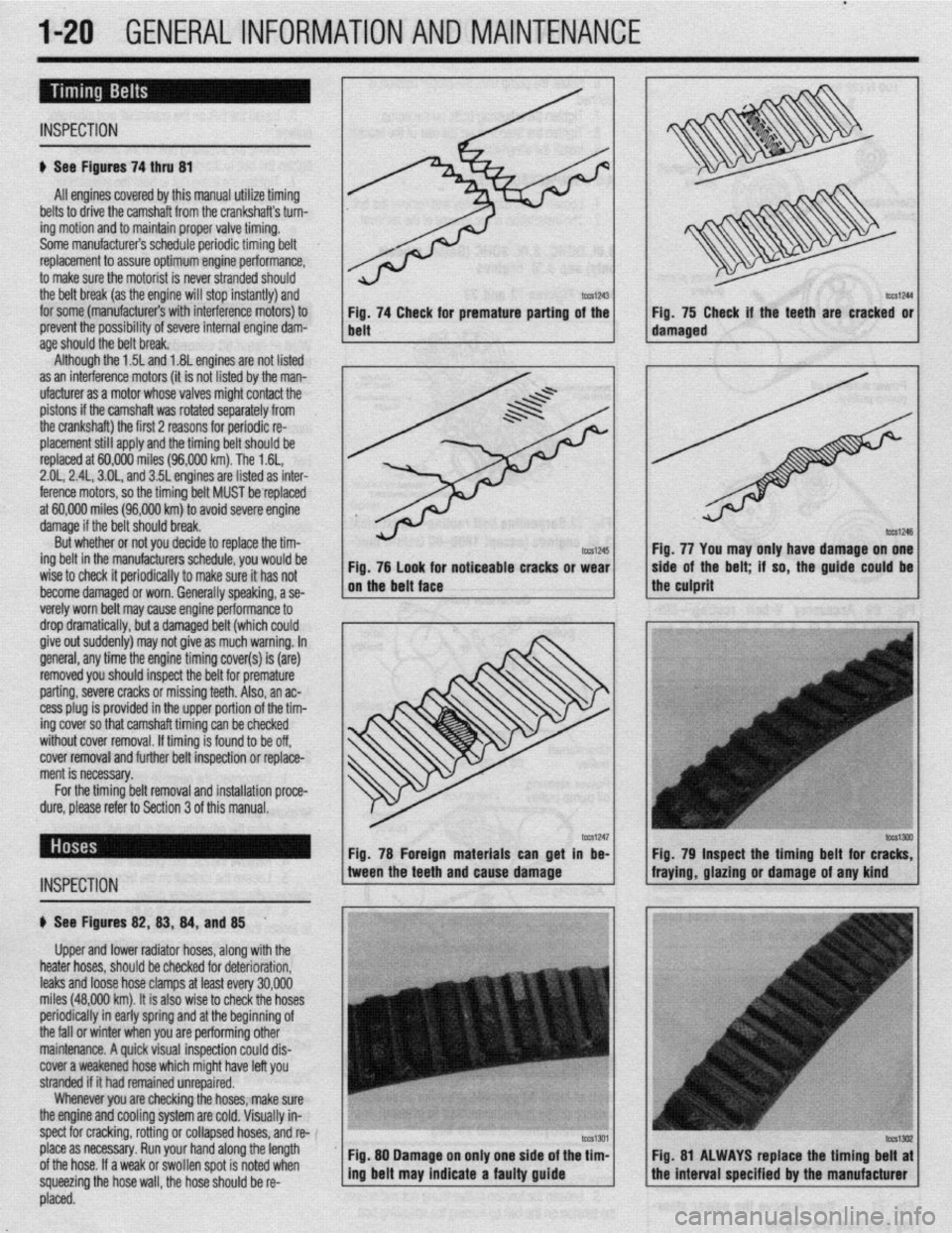
# See Figures 74 thru 81
All engines covered by this manual utilize timing
belts to drive the camshaft from the crankshafts turn-
ing motion and to maintain proper valve timing.
Some manufacturers schedule periodic timing belt
replacement to assure optimum engine performance,
to make sure the motorist is never stranded should
the belt break (as the engine will stop instantly) and
for some (manufacturers with interference motors) to
prevent the possibility of severe internal engine dam-
age
St10Ula the Delt break. Although the 1.5L and 1.8L engines are not listed
as an interference motors (it is not listed by the man-
ufacturer as a motor whose valves might contact the
pistons if the camshaft was rotated separately from
the crankshaft) the first 2 reasons for periodic re-
placement still apply and the timing belt should be
replaced at 60,000 miles (96,000 km). The 1.6L,
2.01,2.4L, 3.OL, and 35L engines are listed as inter-
ference motors, so the timing belt MUST be replaced
at 60,000 miles (96,000 km) to avoid severe engine
damage if the belt should break.
But whether or not you decide to replace the tim-
ing belt in the manufacturers schedule, you would be
wise to check it periodically to make sure it has not
become damaged or worn. Generally speaking, a se-
verelv worn belt mav cause enaine oerformance to
drop~dramatically, but a damaged belt (which could
give out suddenly) may not give as much warning. In
general, any time the engine timing cover(s) is (are)
removed you should inspect the belt for premature
parting, severe cracks or missing teeth. Also, an ac-
cess plug is provided in the upper portion of the tim-
ing cover so that camshaft timing can be checked
without cover removal. If timing is found to be off,
cover removal and further belt inspection or replace-
ment is necessary.
tml245 Fig. 76 look for noticeable cracks or wear
on the belt face
_
For the timing belt removal and installation proce-
dure, please refer to Section 3 of this manual. Fig. 74 Check for premature parting of the
belt
INSPECTION
. 75 Check if the teeth are cracked or
fig. 77 You may only have damage on one
side of the belt; if so, the guide could be
the culprit
b See Figures 82,8S, 84, and 85 .
Upper and lower radiator hoses, along with the
heater hoses, should be checked for deterioration,
leaks and loose hose clamps at least every 30,000
miles (48,000 km). It is also wise to check the hoses
periodically in early spring and at the beginning of
the fall or winter when you are performing other
maintenance. A quick visual inspection could dis-
cover a weakened hose which might have left you
stranded if it had remained unrepaired.
Whenever you are checking the hoses, make sure
the engine and cooling system are cold. Visually in-
spect for cracking, rotting or collapsed hoses, and w-
place as necessary. Run your hand along the length
of the hose. If a weak or swollen spot is noted when
squeezing the hose wall, the hose should be re- Fig. 78 Foreign materials can get in be- Fig. 79 Inspect the timing belt for c
tween the teeth and cause damage fraying, glazing or damage of any kind
Fig. 80 Damage on only one side of the tim-
I I Fig. 81 ALWAYS replace the timing belt at
ing belt may indicate a faulty guide
the interval specified by the manufacturer
, L placed.
Page 20 of 408
GENERALINFORMATIONAND MAINTENANCE l-21
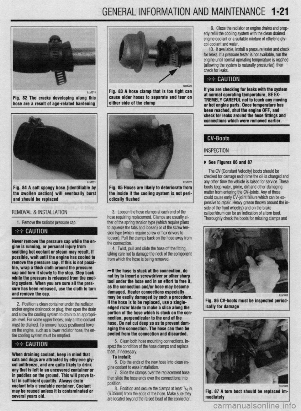
IWSIZXJ FM. 83 A hose clamn that is taa tiaht can
Fig. 82 The cracks developing along this
hose are a result of age-related hardening caise older hoses td separate and ‘iear on
either side of the clamp
lCCS1221 Fig. 84 A soft spongy hose (identifiable by
1 the swollen section) will eventually burst
and should be replaced
IEMOVAL &,INSTALLATION '
1. Remove the radiator pressure cap. her of the sorina tension tvoe (which reouire oliers
3 squeeze the 6bs and loosenj or of the’screw ten-
ion type (which require screw or hex drivers to
oosen). Pull the clamps back on the hose away from
he connection. Never remove the pressure cap while the en-
gine is running, or personal injury from
scalding hot coolant or steam may result. If
possible, wait until the engine has cooled to
remove the pressure cap. If this is not possi-
ble, wrap a thick cloth around the pressure
cap and turn it slowly to the stop. Step back
while the pressure is released from the cool-
ing system. When you are sure all the pres-
sure has been released, use the cloth to turn
and remove the cao.
2. Position a clean container under the radiator
and/or engine draincock or plug, then open the drain
and allow the cooling system to drain to an appropri-
ate level. For some upper hoses, only a little coolant
must be drained. To remove hoses positioned lower
on the engine, such as a lower radiator hose, the en-
tire cooling system must be emptied.
When draining coolant, keep in mind that
cats and dogs are attracted by ethylene gly-
col antifreeze, and are quite likely to drink
any that is left in an uncovered container or
in puddles on the ground. This will prove fa-
tal in sufficient quantity. Always drain
coolant into a sealable container. Coolant
may be reused unless it is contaminated or
several years old. 9. Close the radiator or engine drains and prop-
erly refill the cooling system with the clean drained
engine coolant or a suitable mixture of ethylene gly-
cot coolant and water.
10. If available, install a pressure tester and check
for leaks. If a pressure tester is not available, run the
engine until normal operating temperature is reached
(allowing the system to naturally pressurize), then
check for leaks.
If you are checking for leaks with the system
at normal operating temperature, BE EX-
TREMELY CAREFUL not to touch any moving
or hot engine parts. Once temperature has
been reached. shut the enaine OFF. and
Fig. 85 Hoses are likely to deteriorate from
the inside if the cooling system is not peri-
odically flushed check for leaks around the-hose fittings and
connections which were removed earlier.
INSPECTION
b See Figures 88 and 87
The CV (Constant Velocity) boots should be
checked for damage each time the oil is changed and
any other time the vehicle is raised for service. These
boots keep water, grime, dirt and other damaging
matter from entering the CV-joints. Any of these
could cause early CV-joint failure which can be ex-
pensive to repair. Heavy grease thrown around the in-
side of the front wheel(s) and on the brake
caliper/drum can be an indication of a torn boot.
Thorouahlv check the boots for missina clamos and 3. Loosen the hose clamps at each end of the
rose requiring replacement. Clamps are usually ei-
4. Twist, pull and slide the hose off the fitting,
sking care not to damage the neck of the component
rom which the hose is being removed.
*If the hose is stuck at the connection, do
lot try to insert a screwdriver or other sharp
ool under the hose end in an eff art to free it,
IS the connection and/or hose may become
lamaged. Heater connections especially
nay be easily damaged by such a procedure.
f the hose is to be replaced, use a single-
!dged razor blade to make a slice along the
lortion of the hose which is stuck on the con-
section, perpendicular to the end of the
lose. 00 not cut deep so as to prevent dam-
aging the connection. The hose can then be
keeled from the connection and discarded. Fig. 86 CV-boots must be inspected period-
5.. Clean both hose mounting connections. In-
,pect the condition of the hose clamps and replace
hem, if necessary.
To install:
6. Dip the ends of the new hose into clean en-
fine coolant to ease installation.
7. Slide the clamps over the replacement hose,
hen slide the hose ends over the connections into
rosition.
8. Position and secure the clamps at least l/d in.
6.35mm) from the ends of the hose. Make sure they
Ire located beyond the raised bead of the connector.
Page 27 of 408
l-28 GENERALINFORMATIONAND MAINTENANCE
may result in skin or eye irritation or frostbite. Al- formed to help maintain the efficiency of the vehicle’s
though low in toxicity (due to chemical stability), in- A/C system. For preventive maintenance, perform the
The idle speed is factory set and usually no ad- halation of concentrated refrigerant fumes is danger- following:
justments are ever necessary. If an adjustment be- ous and can result in death; cases of fatal cardiac
l The easiest and most important preventive
comes necessary, first check that the spark plugs, in- arrhythmia have been reported in people accidentally maintenance for your A/C system is to be sure that it
jectors, idle air control servo and compression subjected to high levels of refrigerant. Some early is used on a regular basis. Running the system for
pressure are all normal. symptoms include loss of concentration and drowsi- five minutes each month (no matter what the season)
Data from various sensors and switches are used ness. + will help ensure that the seals and all internal compo-
by the ECU to determine the proper fuel/air mixture
for optimal engine performance. cGeneraiiy, the limit for exposure is lower nents remain lubricated.
for R-134a than it is for R-12. Exceptional *Some newer vehicles automatically oper-
care must be practiced when handling R- ate the A/C system compressor whenever the
134a. windshield defroster is activated. When run-
Also, refrigerants can decompose at high tempera- ning, the compressor lubricates the A/C sys
tures (near gas heaters or open flame), which may re- tern components; therefore, the A/C system
SYSTEM SERVICE& REPAIR suit in hydrofluoric acid, hydrochloric acid and phos- would not need to be operated each month.
gene (a fatal nerve gas). * In order to prevent heater core freeze-up during
R-12 refrigerant can damage the environment be- A/C operation, it is necessary to maintain proper an-
cause it is a Chlorofluorocarbon (CFC), which has tifreeze protection. Use a hand-held coolant tester
been proven to add to ozone layer depletion, leading (hydrometer) to periodically check the condition of
to increasing levels of UV radiation. UV radiation has the antifreeze in your engine’s cooling system.
been linked with an increase in skin cancer, suppres-
sion of the human immune system, an increase in *Antifreeze should not be used longer than
cataracts, damage to crops, damage to aquatic organ- the manufacturer specifies.
isms, an increase in ground-level ozone, and in- . For efficient operation of an air conditioned ve-
creased global warming. hicle’s cooling system, the radiator cap should have a
R-134a refrigerant is a greenhouse gas which, if holding pressure which meets manufacturers specifi-
allowed to vent into the atmosphere, will contribute to cations. A cap which fails to hold these pressures
global warming (the Greenhouse Effect). should be replaced.
It is usually more economically feasible to have a
l Any obstruction of or damage to the condenser
certified MVAC automotive technician perform A/C configuration will restrict air flow which is essential
system service on your vehicle. Some possible rea- to its efficient operation. It is, therefore, a good rule
sons for this are as follows: to keep this unit clean and in proper physical shape.
l While it is illegal to service an A/C system
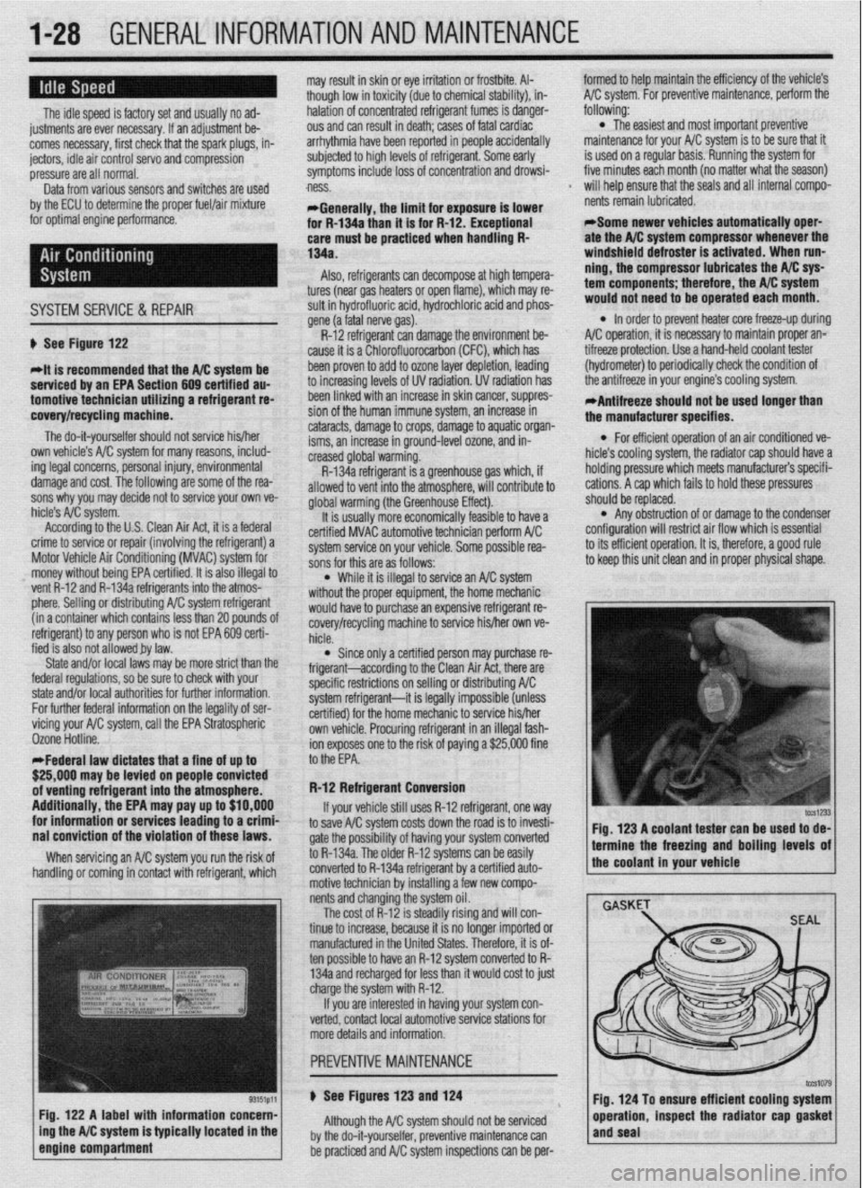
without the proper equipment, the home mechanic ti See Figure 122
*it is recommended that the A/C svstem be
serviced by an EPA Section 609 cehified au-
tomotivetechnicfan utilizing a refrigerant re-
covery/recycling machfne.
The do-it-yourselfer should not service his/her
own vehicle’s A/C system for many reasons, includ-
ing legal concerns, personal injury, environmental
damage and cost. The following are some of the rea-
sons why you may decide not to service your own ve-
hicle’s A/C system.
According to the U.S. Clean Air Act, it is a federal
crime to service or repair (involving the refrigerant) a
Motor Vehicle Air Conditioning (MVAC) system for
money without being EPA certified. It is also illegal to
vent R-12 and R-134a refrigerants into the atmos-
phere. Selling or distributing A/C system refrigerant
(in a container which contains less than 20 pounds oi
refrigerant) to any person who is not EPA 609 certi-
fied is also not allowed by law.
State and/or local laws may be more strict than the
federal regulations, so be sure to check with your
state and/or local authorities for further information.
For further federal information on the legality of ser-
vicing your AK system, call the EPA Stratospheric
Ozone Hotline.
*Federal law dictates that a fine of up to
$25,000 may be levied on people convicted
of venting refrigerant into the atmosphere.
Additionally, the EPA may pay up to $10,000
for information or services leading to a crimf
nai conviction of the violation of these laws.
When servicing an A/C system you run the risk of
handling or coming in contact with refrigerant, which
Fig. 122 A label with information concern-
ing the A/C system is typically located in the
engine compartment
f would haveto purchase an expensive refrigerant re-
covery/recycling machine to service his/her own ve-
hicle.
l Since only a certified person may purchase re-
frigerant-according to the Clean Air Act, there are
specific restrictions on selling or distributing A/C
system refrigerant-it is legally impossible (unless
certified) for the home mechanic to service his/her
own vehicle. Procuring refrigerant in an illegal fash-
ion exposes one to the risk of paying a $25,000 fine
to the EPA.
R-12 Refrigerant Conversion
If your vehicle still uses R-12 refrigerant, one
way to save A/C system costs down the road is to invesh-
gate the possibility of having your system converted
to R-134a. The older R-12 systems can be easily
converted to R-134a refrigerant by a certified auto-
motive technician by installing a few new compo-
nents and changing the system oil.
The cost of R-12 is steadily rising and will con-
tinue to increase, because it is no longer imported or
manufactured in the United States. Therefore, it is of-
ten possible to have an R-12 system converted to R-
134a and recharged for less than it would cost to just
charge the system with R-12.
If you are interested in having your system con-
verted, contact local automotive service stations for
more details and information.
u See Figures 123 and 124
Although the A/C system should not be serviced
by the do-it-yourselfer, preventive maintenance can
be practiced and A/C system inspections can be per- Fig. 123 A coolant tester can be used to de-
1 termine the freezing and boiling levels of
the coolant in your vehicle
Fig. 124 To ensure efficient cooling system
operation, inspect the radiator cap gasket
and seal
Page 38 of 408
GENERALINFORMATIONAND MAINTENANCE 1-39
leak. In most cases, you will be able to trace the leak
to a loose fitting or damaged hose.
Evaporating ethylene glycol antifreeze will have a
sweet smell and leave small, white (salt-like) de-
oosits, which can be heloful in tracino a leak. glove box and passenger side floorboard area, and
check the carpet for any signs of moisture. The
smartest way to go about finding a leak visually is to
first inspect any and all joints in the system such as
where the radiator hoses connect to the radiator and
the engine. Another thing to look for is white crusty
stains that are signs of a leak where the coolant has
6. Install the filler plug and tighten to’24 ft. Ibs.
(32 Nm).
7. If raised, carefully lower the vehicle. amount of fluid. The level should ieach thk bottom of me rating on It, lap3 1s a danciara 10 use out some
the oil filler hole. A Qss
tin,t.as ran +tw,, 4liE cars are higher. Overpressurizing the system can
lose, or worse, in the radiator or
your cooling system is con- IIC~KI LUG MU PuaJbly cause an injury or a burn if
s of a leak are probable. There the coolant is hot. Overpressurizing is normally con-
WI” U”.VlUl ,.“,,I I” 9” about finding the source of trolled by the radiator cap which has a vent valve in it
your leak. which is opened when the system reaches it’s maxi-
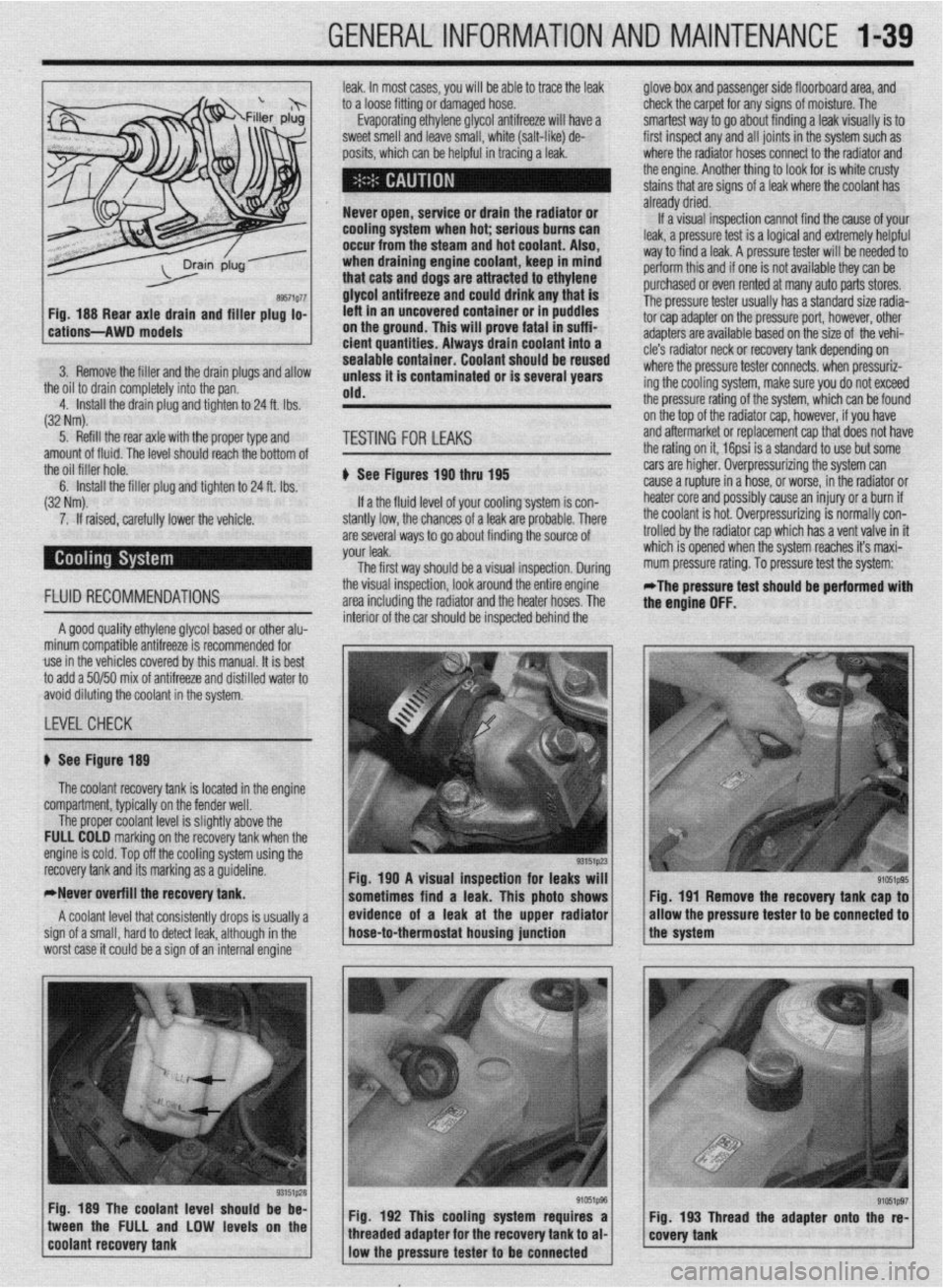
The first wav should be a visual insnection. Durina mum pressure rating. To pressure test the system: 7 “1sl I ly”lsJa IJ” Wll” IJU
If a the fluid level of
stantly low, the chance cause a rupture in a I:
h.n+n. nrrrn nnA . . . . ..I.
FLUID RECOMMENDATIONS the visual inspection, look around the &tire engine -
area including the radiator and the heater hoses. The *The pressure test should be performed with
the enaine OFF.
A good quality ethylene glycol based or other alu-
minum compatible antifreeze is recommended for
use in the vehicles covered by this manual. It is best
to add a 50150 mix of antifreeze and distilled water to
avoid diluting the coolant in the system. interior of the car should be inspected behind the
LEVELCHECK
recovery tank and its marking as a guideline.
*Never overfill the recovery tank.
A coolant level that consistently drops is usually a
sign of a small, hard to detect leak, although in the
worst case it could be a sign of an internal engine “_y “,~--
1 Fia. 190 A visual insaection for leaks will 1
sometimes find a leak. This photo shows Fig. 191 Remove the recovery tank cap to
/ * ,, / evfdence of a leak at the upper radfator
* / /the system allow the pressure tester
to be connected to hose-to-thermostat housing junction
Fig. 189 The coolant level should be be-
1 coo,ant recovery tank tween the FULL and LOW levels on the
“‘~‘_I j Fig. 192 This cooling system requires a Fig. 193 Thread the adapter onto the re-
e’ffi1pg7 / g’051p96 / 1 covety tank threaded adapter for the recovery tank to al-
low the pressure tester to
be connected
Page 45 of 408
.
I-46 GENERALINFORMATIONAND MAINTENANCE
2. Pull the jumping vehicle (with the good bat-
tery) into a position so the jumper cables can reach
the dead battery and that vehicle’s engine. Make sure
that the vehicles do NOT touch.
3. Place the transmissions/transaxles of both ve-
hicles in Neutral (MT) or P (AT), as applicable, then
firmly set their parking brakes.
*ff necessary for safety reasons, the hazard
lights on both vehicles may be operated
throughout the entire procedure without sig-
nificantiy increasing the diff icuity of jumping
the dead battery.
4. Turn all lights and accessories OFF on both
vehicles. Make sure the ignition switches on both ve-
hicles are turned to the OFF position.
5. Cover the battery cell caps with a rag, but do
not cover the terminals.
6. Make sure the terminals on both batteries are
clean and free of corrosion or proper electrical con-
nection will be impeded. If necessary, clean the bat-
tery terminals before proceeding.
7. Identify the positive (+) and negative (-) termi-
nals on both batteries.
8. Connect the first jumper cable to the positive
(t) terminal of the dead battery, then connect the
other end of that cable to the positive (t) terminal of
the booster (good) battery.
9. Connect one end of the other jumper cable to
the negative (−) terminal on the booster bat-
tery and the final cable clamp to an engine bolt head,
alternator bracket or other solid, metallic point on the
engine with the dead battery. Try to pick a ground on
the engine that is positioned away from the battery in
order to minimize the possibility of the 2 clamps
touching should one loosen during the procedure.
DO NOT connect this clamp to the negative (-) termi-
nal of the bad battery. cable on the donor battery. Disconnect the positive
cable from the donor battery and finally, disconnect
the positive cable from the formerly dead battery. Be
careful when disconnecting the cables from the posi-
tive terminals not to allow the alligator clips to touch
any metal on either vehicle or a short and sparks will
occur.
I
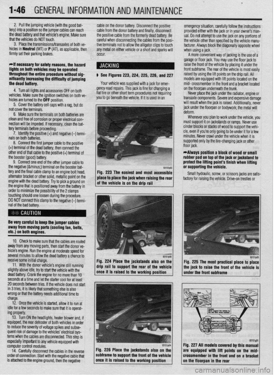
$ See Figures 223,224, 225,226, and 227
Your vehicle was supplied with a jack for emer-
gency road repairs. This jack is fine for changing a
flat tire or other short term procedures not requiring
you to go beneath the vehicle. If it is used in an emergency situation, carefully follow the instructions
provided either with the jack or in your owners man-
ual. Do not attempt to use the jack on any portions of
the vehicle other than specified by the vehicle manu-
facturer. Always block the diagonally opposite wheel
when using a jack.
A more convenient way of jacking is the use of a
garage or floor jack. You may use the floor jack to
raise the front of the vehicle by placing it under the
front subframe. The rear of the vehicle is most easily
raised by using the lift points on the drip rail. All
models are equipped with lift points located on the
mid- crossmember in the front and a bracket located
on the floorpan underneath the trunk.
Never place the jack under the radiator, engine or
transaxle components. Severe and expensive damage
will result when the jack is raised. Additionally, never
jack under the floorpan or
bodywork; the
metal will
Whenever you plan to work under the vehicle, you
must support it on jackstands or ramps. Never use
cinder blocks or stacks of wood to support the vehi-
cle, even if you’re only going to be under it for a few
minutes. Never crawl under the vehicle when it is
supported only by the tire-changing jack or other
*Always position a block of wood or small
rubber pad on top of the jack or jackstand to
protect the lifting point’s finish when lifting
or supporting the vehicle.
Small hydraulic, screw, or scissors jacks are satis-
factory for raising the vehicle. Drive-on trestles or
Be very careful to keep the jumper cables
away from moving parts (cooling fan, belts,
etc.) on both engines.
10. Check to make sure that the cables are routed
away from any moving parts, then start the donor ve-
hicle’s engine. Run the engine at moderate speed for
several minutes to allow the dead battery a chance to
receive some initial charge.
11. With the donor vehicle’s engine still running
slightly above idle, try to start the vehicle with the
dead battery. Crank the engine for no more than 10 &stands also on the
Fig. 225 The most practical place to place
front of the vehicle is
seconds at a time and let the starter cool for at least
20 seconds between tries. If the vehicle does not start
in 3 tries, it is likely thatsomething else is also
wrong or that the battery needs additional time to
charge.
12. Once the vehicle is started, allow it to run at
idle for a few seconds to make sure that it is operat-
ing properly.
13. Turn ON the headlights, heater blower and, if
equipped, the rear defroster of both vehicles in order
to reduce the severity of voltage spikes and subse-
quent risk of damage to the vehicles’ electrical sys-
tems when the cables are disconnected. This step is
especially important to any vehicle equipped with
computer control modules.
14. Carefully disconnect the cables in the’reverse
order of connection. Start with the negative cable that
is attached to the engine ground, then the negative Fig. 226 Place the jackstands also
subframe to support the front of the Fig. 227 All models covered by this
are equipped with lift points on t
crossmember in the front and on a
Page 63 of 408
3-2 ENGINEANDENGINEOVERHAUL
REMOVAL &INSTALLATION
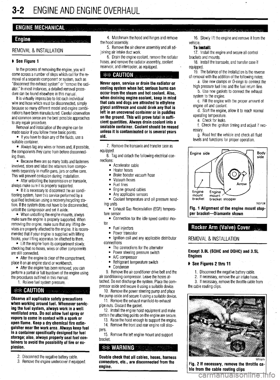
# See Figure 1
In the process of removing the engine, you will
come across a number of steps which call for the re-
moval of a separate component or system, such as
“disconnect the exhaust system” or “remove the radi-
ator.” In most instances, a detailed removal proce-
dure can be found elsewhere in this manual.
It is virtually impossible to list each individual
wire and hose which must be disconnected, simply
because so many different model and engrne combi-
nations have been manufactured Careful observation
and common sense are the best possible approaches
to any repair procedure.
Removal and installation of the engine can be
made easier if you follow these basic points:
l If you have to drain any of the fluids, use a
suitable container.
l Always tag any wires or hoses and, if possrble,
the components they came from before disconnect-
ing them.
l Because there are so many bolts and fasteners
involved, store and label the retainers from compo-
nents separately in muffin pans, jars or coffee cans.
This will prevent confusion during installatron.
l After unbolting the transmisston or transaxle,
always make sure it is properly supported.
l If it is necessary to disconnect the air condi-
tioning system, have this service performed by a
qualified technician using a recovery/recycling sta-
tion If the system does not have to be disconnected,
unbolt the compressor and set it aside.
l When unbolting the engine mounts, always
make sure the engine is properly supported. When
removing the engine, make sure that any lifting de-
vices are properly attached to the engine. It is recom-
mended that if your engine IS supplied with lifting
hooks, your lifting apparatus be attached to them.
l Lift the engine from its compartment slowly,
checking that no hoses, wires or other components
are still connected.
l After the engine is clear of the compartment,
place it on an engine stand or workbench.
l After the engine has been removed, you can
perform a partial or full teardown of the engine using
the procedures outlined in this manual.
1. Relieve fuel system pressure.
Observe all applicable safety precautions
when working around fuel. Whenever servic-
ing the fuel system, always work in a well
ventilated area. Do not allow fuel spray or
vapors to come in contact with a spark or
open flame. Keep a dry chemical fire extin-
guisher near the work area. Always keep fuel
in a container specifically designed for fuel
storage; also, always properly seal fuel con-
tainers to avoid the possibility of fire or ex-
plosion.
2. Disconnect the negative battery cable.
3. Remove the engine undercover if equipped. 4. Matchmark the hood and hinges and remove
the hood assembly.
5. Remove the air cleaner assembly and all ad-
joining air intake duct work.
6. Drain the engine coolant, remove the radiator
hoses, and remove the radiator assembly, coolant
reservoir, and intercooler, as equipped.
cooling system when hot; serious burns can
occur from the steam and hot coolant. Also,
when draining engine coolant, keep in mind
that cats and dogs are attracted to ethylene
glycol antifreeze and could drink any that is
left in an uncovered container or in puddles
on the ground. This will prove fatal in suffi-
cient quantities. Always drain coolant into a
sealable container. Coolant should be reused
unless it is contaminated or is several years
old.
7. Remove the transaxle and transfer case as
equipped.
8. Tag and detach the following electrical con-
nections:
l Accelerator cable l Heater hoses l Brake booster vacuum hose l Vacuum hoses l Fuel lines l Engine ground cables l Any applicable sensors l Coolant temperature and oil pressure send-
ing units
l Exhaust Gas Recirculation (EGR) tempera-
ture sensor
l Connection for the idle speed control mo-
tor
l Fuel injectors l Power transistor l Ignition coil and any applicable distributor
connections
l The connections for the alternator l Power steering pressure switch l A/C compressor l Refrigerant temperature switch l Condenser
9. Remove the air conditioner drive belt and the
air conditioning compressor. Leave the hoses at-
tached. Do not discharge the system. Place the com-
pressor aside and secure it using a suitable device.
10. Remove the power steering pump and place
the pump asrde and secure it using a surtable device.
11. Remove the exhaust manifold-to-exhaust
pipe nuts. Discard the gasket.
12. Install the engine hoist equipment and make
certain the attaching points on the engine are secure.
13. Raise the hoist enough to support the engine.
14. Remove the front and rear engine roll stop-
pers
15. Remove the left engine mount and support
Double check that all cables, hoses, harness
connectors, etc., are disconnected from the
engine.
16. Slowly lift the engine and remove it from the
vehicle.
To install:
17. Install the engine and secure all control
brackets and mounts.
18. Install the transaxle, and transfer case if
equipped.
19. The balance of the installation is the reverse
of removal with the addition of the following notes:
a. Use new clamps or O-rings to connect the
high pressure fuel lme and the fuel return line.
b. Use new gaskets to connect the exhaust
system to the engine.
c. Fill the engine with the proper amount of
engine oil and coolant.
d. Start the engine, allow it to reach normal
operating temperature.
e. Check for leaks.
f. Check the ignition timing and adjust if nec-
essary.
g. Road test the vehicle and check all fluid
levels and functions for proper operation.
Fig. 1 Alignment of the engine mount stop-
oer bracket-Diamante shown
REMOVAL &INSTALLATION
Except 3.OL (SOHC and DOHC) and 3.5L
Engines
# See Figures 2 thru 11
1. Disconnect the negative battery cable.
2. If necessary, remove the air intake hose.
3. If necessary, remove the throttle cable from
the cable routing clips.
Fig. 2 If necessary, remove the throttle ca-
ble from the cable routing clips
Page 69 of 408
3-8' ENGINEANDENGINEOVERHAUL
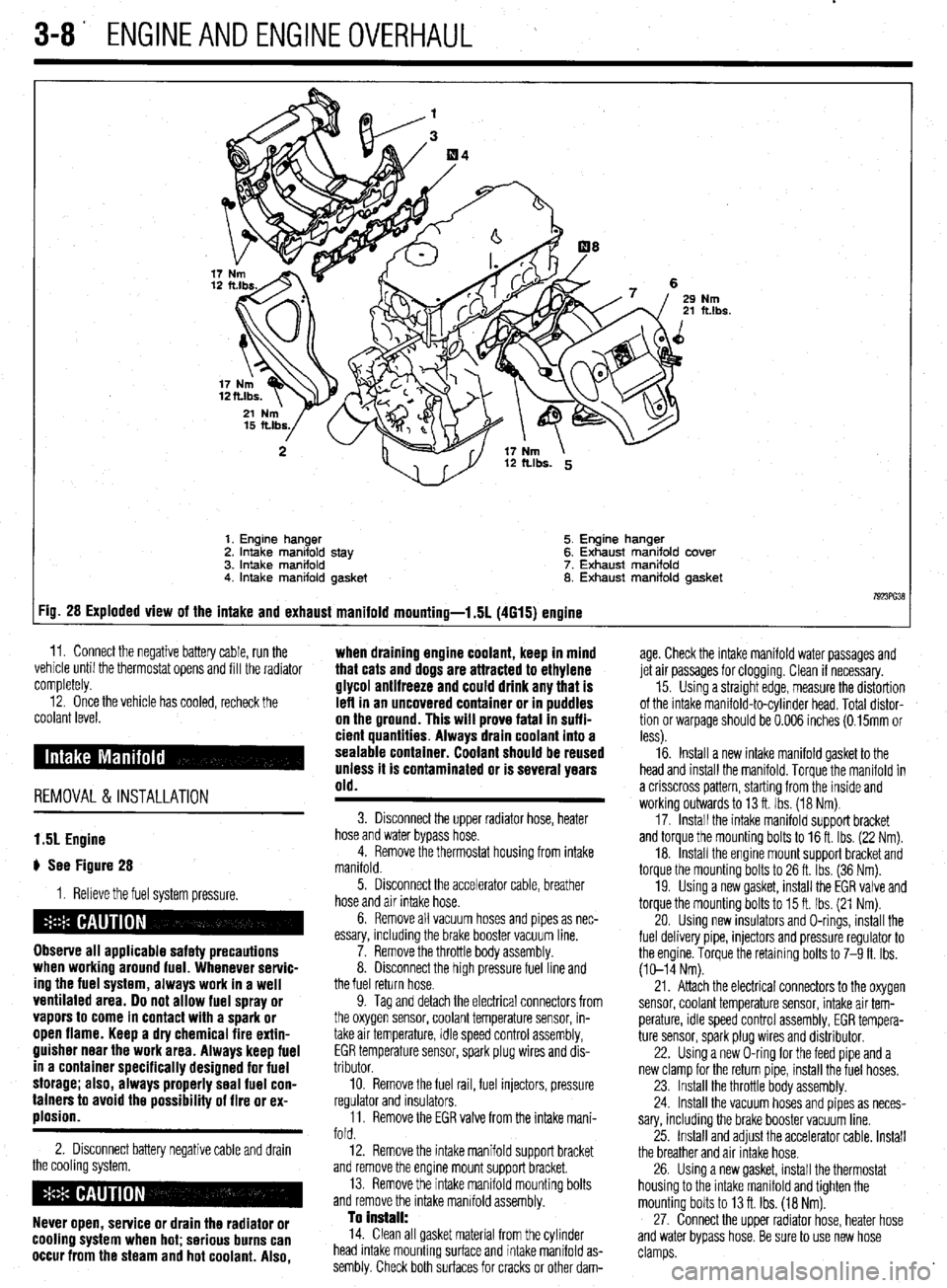
Nm ft.lbs.
1. Engine hanger 5. Engine hanger
2. Intake manifold stay 6. Exhaust manifold cover
3. intake manifold 7. Exhaust manifold
4. Intake manifold gasket 8. Exhaust manifold gasket
7923ffi38 :ig. 28 Exploded view of the intake and exhaust manifold mounting-l .5L (4615) engine
11. Connect the negative battery cable, run the ,. . . .
vemcie unnl me tnermostat opens ano till the radiator
completely. age. Check the intake manifold water passages and
jet air passages for clogging. Clean if necessary.
12. Once the vehicle has cooled, recheck the
coolant level.
REMOVAL &INSTALLATION when draining engine coolant, keep in mind
that cats and dogs are attracted to ethylene
glycol antifreeze and could drink any that is
left in an uncovered container or in puddles
on the ground. This will prove fatal In suffi-
cient quantities. Always drain coolant into a
sealable container. Coolant should be reused
unless it is contaminated or is several years
old.
15. Using a straight edge, measure the distortion
of the intake manifold-to-cylinder head. Total distor-
tion or warpage should be 0.006 inches (0.15mm or
less).
16. Install a new intake manifold gasket to the
head and install the manifold. Torque the manifold in
a crisscross pattern, starting from the inside and
working outwards to 13 ft. Ibs. (18 Nm).
17. Install the intake manifold support bracket
and torque the mounting bolts to 16 ft. Ibs. (22 Nm).
18. Install the engine mount support bracket and
torque the mounting bolts to 26 ft. Ibs. (36 Nm).
19. Using a new gasket, install the EGR valve and
torque the mounting bolts to 15 ft. Ibs. (21 Nm).
20. Using new insulators and O-rings, install the
fuel delivery pipe, injectors and pressure regulator to
the engine. Torque the retaining bolts to 7-9 ft. Ibs.
(10-14 Nm).
1.51 Engine
# See Figure 28
1. Relieve the fuel system pressure.
Observe all applicable safety precautions
when working around fuel. Whenever servic-
ing the fuel system, always work in a well
ventilated area. Do not allow fuel spray or
vapors to come in contact with a spark or
open flame. Keep a dry chemical fire extin-
guisher near the work area. Always keep fuel
in a container specifically designed for fuel
storage; also, always properly seal fuel con-
tainers to avoid the possibility of fire or ex-
plosion.
2. Disconnect battery negative cable and drain
the cooling system.
Never open, service or drain the radiator or
cooling system when hot; serious burns can
occur from the steam and hot coolant. Also,
3. Disconnect the upper radiator hose, heater
hose and water bypass hose.
4. Remove the thermostat housing from intake
manifold.
5. Disconnect the accelerator cable, breather
hose and air intake hose.
6. Remove all vacuum hoses and pipes as nec-
essary, including the brake booster vacuum line.
7. Remove the throttle body assembly.
8. Disconnect the high pressure fuel line and
the fuel return hose.
9. Tag and detach the electrical connectors from
the oxygen sensor, coolant temperature sensor, in-
take air temperature, idle speed control assembly,
EGR temperature sensor, spark plug wires and dis-
tributor.
10. Remove the fuel rail, fuel injectors, pressure
regulator and insulators.
11. Remove the EGR valve from the intake mani-
fold.
12. Remove the intake manifold support bracket
and remove the engine mount support bracket.
13. Remove the intake manifold mounting bolts
and remove the intake manifold assembly.
To Install: 14. Clean all gasket material from the cylinder
head intake mounting surface and intake manifold as-
sembly. Check both surfaces for cracks or other dam- 21. Attach the electrical connectors to the oxygen
sensor, coolant temperature sensor, intake air tem-
perature, idle speed control assembly, EGR tempera-
ture sensor, spark plug wires and distributor.
22. Using a new O-ring for the feed pipe and a
new clamp for the return pipe, install the fuel hoses.
23. Install the throttle body assembly.
24. Install the vacuum hoses and pipes as neces-
sary, including the brake booster vacuum line.
25. Install and adjust the accelerator cable. Install
the breather and air Intake hose.
26. Using a new gasket, install the thermostat
housing to the intake manifold and tighten the
mounting bolts to 13 ft. Ibs. (18 Nm).
27. Connect the upper radiator hose, heater hose
and water bypass hose. Be sure to use new hose
clamps.
Page 70 of 408
ENGINEANDENGINEOVERHAUL 3-9
28. Fill the system with coolant.
29. Connect the negative battery cable, run the
vehicle until the thermostat opens, fill the radiator
completely.
30. Check and adjust the idle speed and ignition
timing.
31. Once the vehicle has cooled, recheck the
coolant level.
1.8L Engine
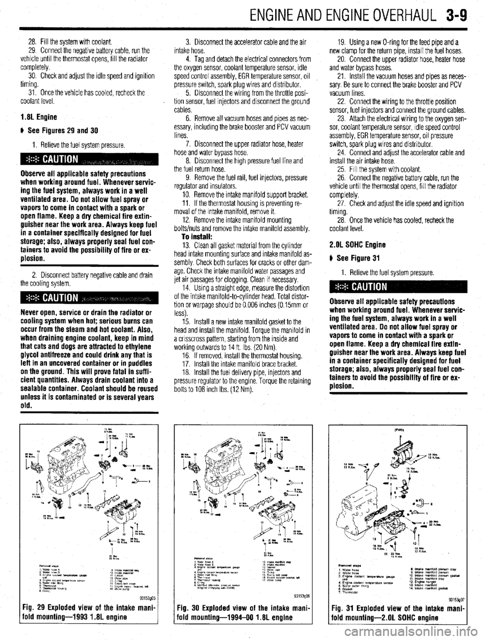
) See Figures 29 and 30
I. Relieve the fuel system pressure.
Observe all applicable safety precautions
when working around fuel. Whenever servic-
ing the fuel system, always work in a well
ventilated area. Do not allow fuel spray or
vapors to come in contact with a spark or
open flame. Keep a dry chemical fire extin-
guisher near the work area. Always keep fuel
in a container specifically designed for fuel
storage; also, always properly seal fuel con-
tainers to avoid the possibility of fire or ex-
plosion.
2. Disconnect battery negative cable and drain
the cooling system.
Never open, service or drain the radiator or
cooling system when hot; serious burns can
occur from the steam and hot coolant. Also,
when draining engine coolant, keep in mind
that cats and dogs are attracted to ethylene
glycol antifreeze and could drink any that is
leff in an uncovered container or in puddles
on the ground. This will prove fatal in suffi-
cient quantities. Always drain coolant into a
sealable container. Coolant should be reused
unless it is contaminated or is several years
old.
Fig. 29 Exploded view of the intake mani.
old mounting-1993 1.8L engine
3. Disconnect the accelerator cable and the air
intake hose.
4. Tag and detach the electrical connectors from
the oxygen sensor, coolant temperature sensor, idle
speed control assembly, EGR temperature sensor, oil
pressure switch, spark plug wires and distributor.
5. Disconnect the wiring from the throttle posi-
tion sensor, fuel Injectors and disconnect the ground
cables.
6. Remove all vacuum hoses and pipes as nec-
essary, including the brake booster and PCV vacuum
lines.
7. Disconnect the upper radiator hose, heater
hose and water bypass hose.
8. Disconnect the high pressure fuel line and
the fuel return hose.
9. Remove the fuel rail, fuel injectors, pressure
regulator and insulators.
10. Remove the intake manifold support bracket.
11. If the thermostat housing is preventing re-
moval of the Intake manifold, remove it.
12. Remove the intake manifold mounting
bolts/nuts and remove the intake manifold assembly.
To install: 13. Clean all gasket material from the cylinder
head intake mounting surface and intake manifold as-
sembly Check both surfaces for cracks or other dam-
age. Check the intake manifold water passages and
jet air passages for clogging. Clean if necessary.
14. Using a straight edge, measure the distortion
of the intake manifold-to-cylinder head. Total distor-
tion or warpage should be 0.006 inches (0.15mm or
less).
15. Install a new intake manifold gasket to the
head and install the manifold. Torque the manifold in
a crrsscross pattern, starting from the inside and
working outwards to 14 ft. Ibs. (20 Nm).
16. If removed, install the thermostat housing.
17. Install the Intake manifold brace bracket.
18. Install the fuel delivery pipe, injectors and
pressure regulator to the engine. Torque the retaining
bolts to 108 Inch Ibs. (12 Nm). 19. Using a new O-ring for the feed pipe and a
new clamp for the return pipe, install the fuel hoses,
20. Connect the upper radiator hose, heater hose
and water bypass hoses.
21. Install the vacuum hoses and pipes as neces-
sary. Be sure to connect the brake booster and PCV
vacuum lines
22. Connect the wiring to the throttle position
sensor, fuel injectors and connect the ground cables,
23. Attach the electrical wiring to the oxygen sen-
sor, coolant temperature sensor, Idle speed control
assembly, EGR temperature sensor, oil pressure
switch, spark plug wires and distributor.
24. Connect and adjust the accelerator cable and
install the air intake hose.
25. Fill the system with coolant.
26. Connect the negative battery cable, run the
vehicle until the thermostat opens, fill the radiator
completely.
27. Check and adjust the idle speed and ignition
timing.
28. Once the vehicle has cooled, recheck the
coolant level. 2.OL SOHC Engine
# See Figure 31
1. Relieve the fuel system pressure.
Observe all applicable safety precautions
when working around fuel. Whenever servic-
ing the fuel system, always work in a well
ventilated area. Do not allow fuel spray or
vapors to come in contact with a spark or
open flame. Keep a dry chemical fire extin-
guisher near the work area. Always keep fuel
in a container specifically designed for fuel
storage; also, always properly seal fuel con-
tainers to avoid the possibility of fire or ex-
plosion.
Fig. 30 Exploded view of the intake mani,
iold mounting-1994-00 1.8L engine Fig. 31 Exploded view of the intake mani
fold mounting-2.01 SOHC ermine