1900 MITSUBISHI DIAMANTE tire pressure
[x] Cancel search: tire pressurePage 20 of 408
GENERALINFORMATIONAND MAINTENANCE l-21
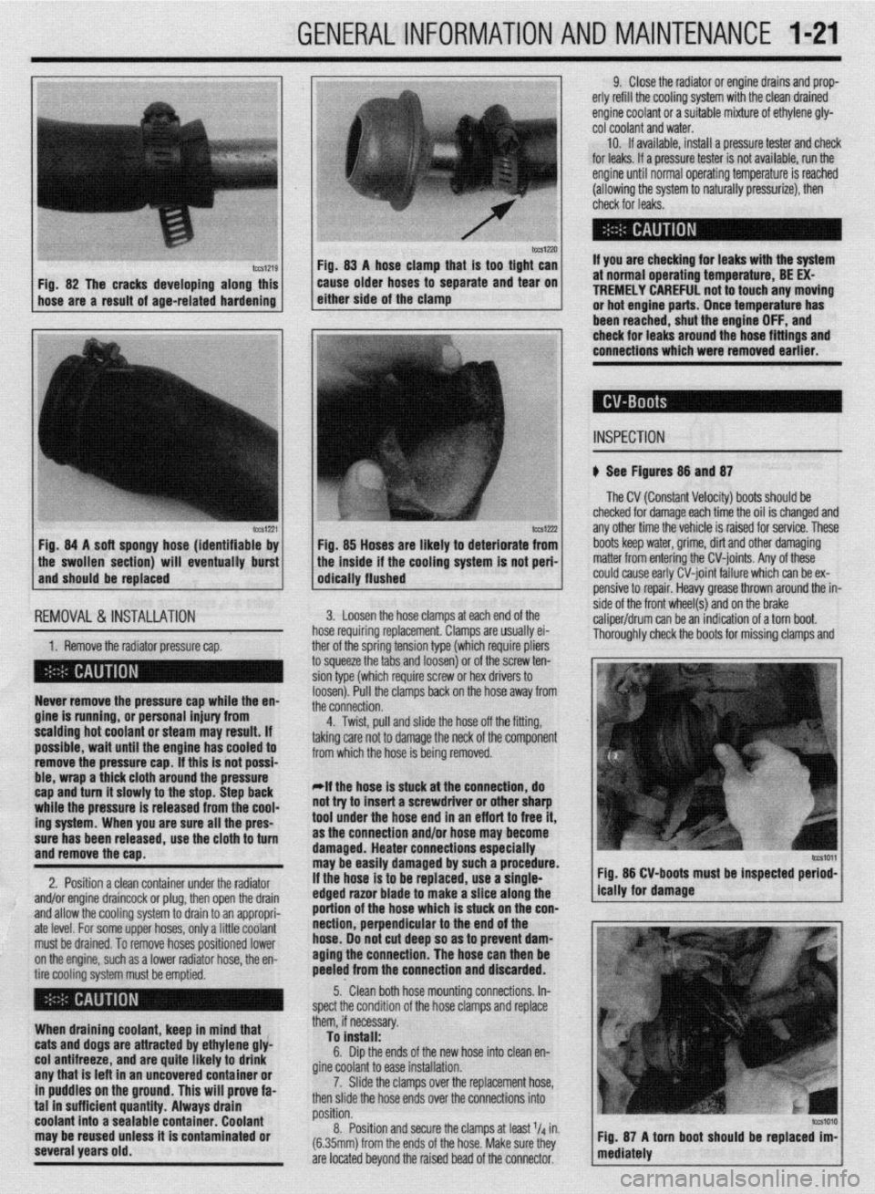
IWSIZXJ FM. 83 A hose clamn that is taa tiaht can
Fig. 82 The cracks developing along this
hose are a result of age-related hardening caise older hoses td separate and ‘iear on
either side of the clamp
lCCS1221 Fig. 84 A soft spongy hose (identifiable by
1 the swollen section) will eventually burst
and should be replaced
IEMOVAL &,INSTALLATION '
1. Remove the radiator pressure cap. her of the sorina tension tvoe (which reouire oliers
3 squeeze the 6bs and loosenj or of the’screw ten-
ion type (which require screw or hex drivers to
oosen). Pull the clamps back on the hose away from
he connection. Never remove the pressure cap while the en-
gine is running, or personal injury from
scalding hot coolant or steam may result. If
possible, wait until the engine has cooled to
remove the pressure cap. If this is not possi-
ble, wrap a thick cloth around the pressure
cap and turn it slowly to the stop. Step back
while the pressure is released from the cool-
ing system. When you are sure all the pres-
sure has been released, use the cloth to turn
and remove the cao.
2. Position a clean container under the radiator
and/or engine draincock or plug, then open the drain
and allow the cooling system to drain to an appropri-
ate level. For some upper hoses, only a little coolant
must be drained. To remove hoses positioned lower
on the engine, such as a lower radiator hose, the en-
tire cooling system must be emptied.
When draining coolant, keep in mind that
cats and dogs are attracted by ethylene gly-
col antifreeze, and are quite likely to drink
any that is left in an uncovered container or
in puddles on the ground. This will prove fa-
tal in sufficient quantity. Always drain
coolant into a sealable container. Coolant
may be reused unless it is contaminated or
several years old. 9. Close the radiator or engine drains and prop-
erly refill the cooling system with the clean drained
engine coolant or a suitable mixture of ethylene gly-
cot coolant and water.
10. If available, install a pressure tester and check
for leaks. If a pressure tester is not available, run the
engine until normal operating temperature is reached
(allowing the system to naturally pressurize), then
check for leaks.
If you are checking for leaks with the system
at normal operating temperature, BE EX-
TREMELY CAREFUL not to touch any moving
or hot engine parts. Once temperature has
been reached. shut the enaine OFF. and
Fig. 85 Hoses are likely to deteriorate from
the inside if the cooling system is not peri-
odically flushed check for leaks around the-hose fittings and
connections which were removed earlier.
INSPECTION
b See Figures 88 and 87
The CV (Constant Velocity) boots should be
checked for damage each time the oil is changed and
any other time the vehicle is raised for service. These
boots keep water, grime, dirt and other damaging
matter from entering the CV-joints. Any of these
could cause early CV-joint failure which can be ex-
pensive to repair. Heavy grease thrown around the in-
side of the front wheel(s) and on the brake
caliper/drum can be an indication of a torn boot.
Thorouahlv check the boots for missina clamos and 3. Loosen the hose clamps at each end of the
rose requiring replacement. Clamps are usually ei-
4. Twist, pull and slide the hose off the fitting,
sking care not to damage the neck of the component
rom which the hose is being removed.
*If the hose is stuck at the connection, do
lot try to insert a screwdriver or other sharp
ool under the hose end in an eff art to free it,
IS the connection and/or hose may become
lamaged. Heater connections especially
nay be easily damaged by such a procedure.
f the hose is to be replaced, use a single-
!dged razor blade to make a slice along the
lortion of the hose which is stuck on the con-
section, perpendicular to the end of the
lose. 00 not cut deep so as to prevent dam-
aging the connection. The hose can then be
keeled from the connection and discarded. Fig. 86 CV-boots must be inspected period-
5.. Clean both hose mounting connections. In-
,pect the condition of the hose clamps and replace
hem, if necessary.
To install:
6. Dip the ends of the new hose into clean en-
fine coolant to ease installation.
7. Slide the clamps over the replacement hose,
hen slide the hose ends over the connections into
rosition.
8. Position and secure the clamps at least l/d in.
6.35mm) from the ends of the hose. Make sure they
Ire located beyond the raised bead of the connector.
Page 29 of 408
.
l-30 GENERAL'INFORMATIONAND MAINTENANCE
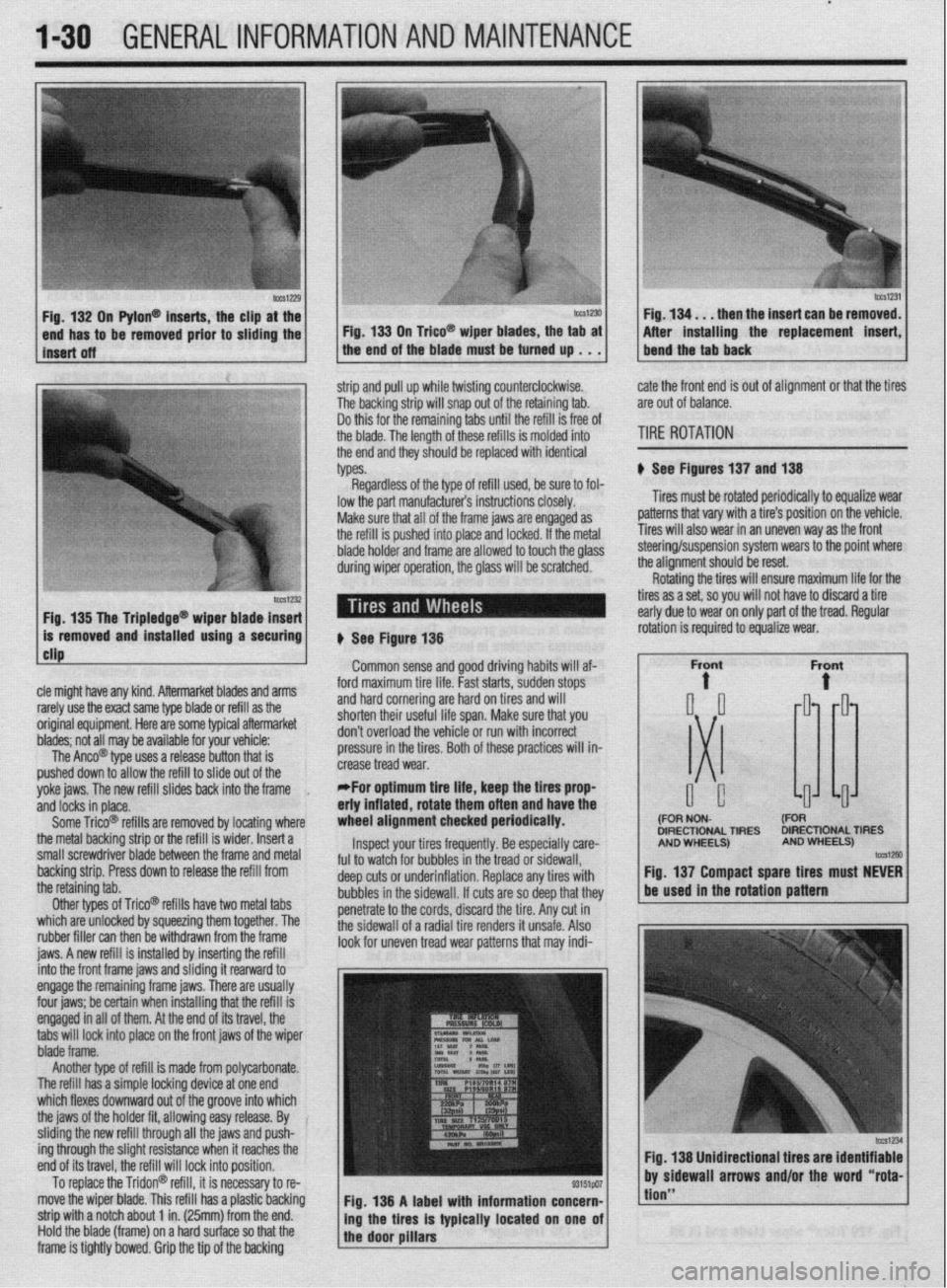
n Pylon@ inserts, the clip
be removed prior to siidi then the insert can be re
After installing the replacement
strip and pull up while twisting counterclockwise.
The backing strip will snap out of the retaining tab.
Do this for the remaining tabs until the refill is free of
the blade. The length of these refills is molded into
the end and they should be replaced with identical
types. cate the front end is out of alignment or that the tires
are out of balance.
TIRE ROTATION
# See Figures 137 and 138
Tires must be rotated periodically to equalize wear
patterns that vary with a tire’s position on the vehicle.
Tires will also wear in an uneven way as the front
1 Fin 1% Tha Trinlarlna@
cle might have any kind. Aftermarket blades and arms
rarely use the exact same type blade or refill as the
original equipment. Here are some typiel aftermarket
blades; not all may be available for your vehicle:
The Anco@ type uses a release button that is
pushed down to allow the refill to slide out of the
yoke jaws. The new refill slides back into the frame
,
and locks in place.
Some Trico@ refills are removed by locating where
the metal backing strip or the refill is wider. Insert a
small screwdriver blade between the frame and metal
backing strip. Press down to release the refill from
the retaining tab.
Other types of Trico@’ refills have two metal tabs
which are unlocked by squeezing them together. The
rubber filler can then be withdrawn from the frame
iaws. A new refill is installed bv insertina the refill lowed to touch the olass steering/suspension system wears to the point where
the alianment should be reset.
# See Figure 138
Common sense and good driving habits will af-
ford maximum tire life. Fast starts, sudden stops
and hard cornering are hard on tires and will
shorten their useful life span. Make sure that you
don’t overload the vehicle or run with incorrect
pressure in the tires. Both of these practices will in-
crease tread wear.
*For optimum tire life, keep the fires prop
eriy inflated, rotate them often and have the
wheel alignment checked periodically.
Inspect your tires frequently. Be especially care-
ful to watch for bubbles in the tread or sidewall,
deep cuts or underinflation. Replace any tires with
bubbles in the sidewall. If cuts are so deep that they
penetrate to the cords, discard the tire. Any cut in
the sidewall of a radial tire renders it unsafe. Also
look for uneven tread wear patterns that may indi- Rotating the tires will ensure maximum life for the
tires as a set, so you will not have to discard a tire
early due to wear on only part of the tread. Regular
DIRECTIONAL TIRES DIRECTIONAL TIRES
jnto the front frame jaws and &ding it rearward to
engage the remaining frame jaws. There are usually
four jaws; be certain when installing that the refill is
engaged in all of them. At the end of its travel, the
tabs will lock into place on the front jaws of the wiper
blade frame.
Another type of refill is made from polycarbonate.
The refill has a simple locking device at one end
which flexes downward out of the groove into which
the jaws of the holder fit, allowing easy release. By
sliding the new refill through all the jaws and push-
ing through the slight resistance when it reaches the
end of its travel, the refill will lock into position.
To replace the Tridon@ refill, it is necessary to re-
move the wiper blade. This refill has a plastic backing
strip with a notch about 1 in. (25mm) from the end.
Hold the blade (frame) on a hard surface so that the
frame is tightly bowed. Grip the tip of the backing Fig. 138 A label with information concern-
ing the tires is typically located on one of
the door pillars
tion”
Page 30 of 408
GENERALINFORMATIONAND MAlNTENANdE 1-31
When rotating “unidirectional tires,” make sure
that they always roll in the same direction. This
means that a tire used on the left side of the vehicle
must not be switched to the right side and vice-versa.
Such tires should only be rotated front-to-rear or
rear-to-front, while always remaining on the same
side of the vehicle. These tires are marked on the
sidewall as to the direction of rotation; observe the
marks when reinstalling the tire(s).
Some styled or “mag” wheels may have different
offsets front to rear. In these cases, the rear wheels
must not be used up front and vice-versa. Further-
more, if these wheels are equipped with unidirectional
tires, they cannot be rotated unless the tire is re-
mounted for the proper direction of rotation.
*The compact or space-saver spare is
strictly for emergency use. it must never be
included in the tire rotation or placed on the
vehicle for everyday use. check the installed tire for any sign of interference
with the body or suspension while the vehicle is stop-
ping, turning sharply or heavily loaded.
Snow Tires
Good radial tires can produce a big advantage in
slippery weather, but in snow, a street radial tire does
not have sufficient tread to provide traction and con-
trol. The small grooves of a street tire quickly pack
with snow and the tire behaves like a billiard ball on a
marble floor, The more open, chunky tread of a snow
tire will self-clean as the tire turns, providing much
better grip on snowy surfaces.
To satisfy municipalities requiring snow tires dur-
ing weather emergencies, most snow tires carry either
an M + S designation after the tire size stamped on
the sidewall, or the designation “all-season.” In gen-
eral, no change in tire size is necessary when buying
snow tires.
Most manufacturers stronqlv recommend the use styled wheels, see if inexpensive steel
wheels are available, Although the look of
the vehicle will change, the expensive
wheels will be protected from salt, curb hits
and pothole damage.
TIRESTORAGE
If they are mounted on wheels, store the tires at
proper inflation pressure. All tires should be kept in a
cool, dry place. If they are stored in the garage or
basement, do not let them stand on a concrete floor;
set them on strips of wood, a mat or a large stack of
newspaper. Keeping them away from direct moisture
is of paramount importance. Tires should not be
stored upright, but in a flat position.
INFLATION & INSPECTION
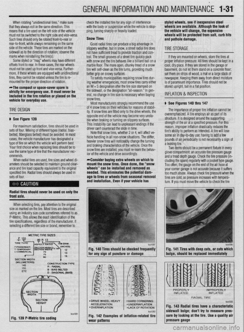
b See Figures 140 thru 147
TIRE DESIGN
p See Figure 139
for maximum satisfaction, tires should be used in
sets of four. Mixing of different types (radial, bias-
belted, fiberglass belted) must be avoided. In most
cases, the vehicle manufacturer has designated a
type of tire on which the vehicle will perform best.
Your first choice when replacing tires should be to
use the same type of tire that the manufacturer rec-
ommends.
When radial tires are used, tire sizes and wheel di-
ameters should be selected to maintain ground clear-
ante and tire load caoacitv eauivalent to the oriainal
specified tire. Radial tiresshould always be used in
sets of four. of 4 snow tires on their
lehicies for reasons of stabil-
ity. If snow tires are fitter
1 only to the drive wheels, the
opposite end of the vehil cle may become very unsta-
ble when braking or turn
ring on slippery surfaces.
This instability can lead to unpleasant endings if the
A*:,,“- r-..l, ^_.. ..& ^_^^, &I.
UIIVU MII I LUUII~~MLL iue slide in time.
Note that snow tires, whether 2 or 4, will affect ve-
hicle handling in all non-snow situations. The stiffer,
heavier snow tires will noticeably change the turning
and braking characteristics of the vehicle. Once the
snow tires are installed, you must re-learn the behav-
ior of the vehicle and drive accordingly.
*Consider buying extra wheels on which to
mount the snow tires. Once done, the “snow
iheeis” can be installed and removed as
needed. This eliminates the potential
dam- age to tires or wheels from seasonal removal
and installation. Even if your vehicle has
lb The importance of proper tire inflation cannot be
overemphasized. A tire employs air as part of its
structure. It is designed around the supporting
strength of the air at a specified pressure. For this
reason, improper inflation drastically reduces the
tire’s ability to perform as intended. A tire will lose
some air in day-to-day use; having to add a few
pounds of air periodically is not necessarily a sign of
a leaking tire.
Two items should be a permanent fixture in every
glove compartment: an accurate tire pressure gauge
and a tread depth gauge. Check the tire pressure (in-
eluding the spare) regularly with a pocket type gauge.
Too often, the gauge on the end of the air hose at
vnr rr corner narane is not accurate because it suffers
~rs check tire oressure when the
Radial tires should never be used on only the
XI I._.
‘-’ --“‘“’ J s too much abuse. Alwa!
tires are cold, as pressure increases with tempera-
ture. If you must move the vehicle to check the tire
front axle.
When selecting tires, pay attention to the original
size as marked on the tire. Most tires are described
using an industry size code sometimes referred to as
P-Metric. This allows the exact identification of the
tire specifications, regardless of the manufacturer. If
selecting a different tire size or brand, remember to
METRIC TIRE SIZES
(MILLIMETERS)
145 CDNStRUCtlDN l-6-E
R - RADIAL
D
WA9
Fig. 139 P-Metric tire coding Fig. 140 Tires should be checked frequently
I I Fig. 141 Tires with deep cuts, or cuts which
for any sion of auncture or damaoe
buioe, should be replaced immediately
l DRIVE WHEEL HEAW
ACCELERATION
l OVERINFLATION
*LACK OF ROTATION
Fig. 142 Examples of inflation-related tire
RADIAL TIRE
fig. 143 Radial tires have a characteristic
sidewall bulge; don’t try to measure pres-
sure by looking at the tire. Use a quality air
pressure gauge
Page 31 of 408
.
1-32 GENERALINFORMATIONAND MAINTENANCE
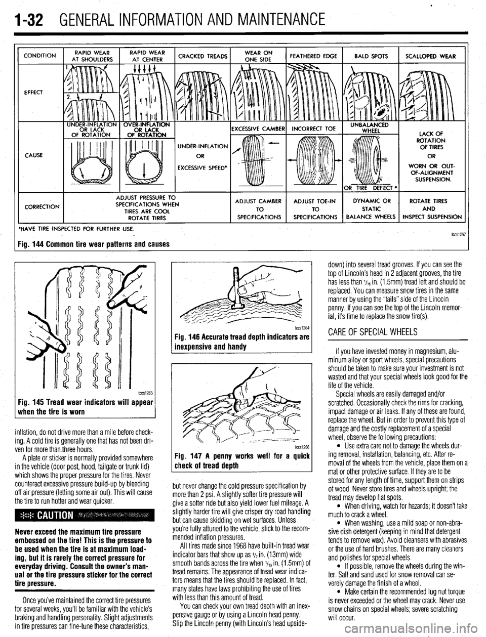
CONDITION
EFFECT
CAUSE
CORRECTION UNDER-INFLATION
EXCESSIVE SPEED’ WORN OR OUT-
OF-ALIGNMENT
ADJUST PRESSURE TO
SPECIFICATIONS WHEN
TIRES ARE COOL
ROTATE TIRES
/ BALANCE WHEELS INSPECT SUSPENSION
HAVE TIRE INSPECTED FOR FURTHER USE.
lCCSi267 ig. 144 Common tire wear patterns and causes
1~~~1265 Fig. 145 Tread wear indicators will appear
when the tire is worn
inflation, do not drive more than a mile before check-
ing. A cold tire is generally one that has not been dri-
ven for more than three hours.
A plate or sticker is normally provided somewhere
in the vehicle (door post, hood, tailgate or trunk lid)
which shows the proper pressure for the tires. Never
counteract excessive pressure build-up by bleeding
off air pressure (letting some air out). This will cause
the tire to run hotter and wear quicker.
Never exceed the maximum tire pressure
embossed on the tire! This is the pressure to
be used when the tire is at maximum load-
ing, but it is rarely the correct pressure for
everyday driving. Consult the owner’s man-
ual or the tire pressure sticker for the correct
tire pressure.
Once you’ve maintained the correct tire pressures
for several weeks, you’ll be familiar with the vehicle’s
braking and handling personality. Slight adjustments
in tire pressures can fine-tune these characteristics,
1~~~1264 Fig. 146 Accurate tread depth indicators are
inexuensive and handv
Fig. 147 A penny works well for a quick
check of tread death
but never change the cold pressure specification by
more than 2 psi. A slightly softer tire pressure will
give a softer ride but also yield lower fuel mileage. A
slightly harder tire will give crisper dry road handling
but can cause skidding on wet surfaces. Unless
you’re fully attuned to the vehicle, stick to the recom-
mended inflation pressures.
All tires made since 1968 have built-in tread wear
indicator bars that show up as j/2 in. (13mm) wide
smooth bands across the bre when V,~ in. (1.5mm) of
tread remains. The appearance of tread wear indica-
tors means that the tires should be replaced. In fact,
many states have laws prohibiting the use of tires
with less than this amount of tread.
You can check your own tread depth with an inex-
pensive gauge or by using a Lincoln head penny.
Shp the Lrncoln penny (with Lincoln’s head upside- down) into several tread grooves. If you can see the
top of Lincoln’s head in 2 adjacent grooves, the tire
has less than V,~ in. (1.5mm) tread left and should be
replaced. You can measure snow tires in the same
manner by using the “tails” side of the Lincoln
penny. If you can see the top of the Lincoln memor-
ial, its time to replace the snow tire(s).
CAREOFSPECIALWHEELS
If you have invested money in magnesium, alu-
minum alloy or sport wheels, special precautions
should be taken to make sure your investment is not
wasted and that your special wheels look good for the
life of the vehicle.
Special wheels are easily damaged and/or
scratched. Occasionally check the rims for cracking,
impact damage or air leaks. If any of these are found,
replace the wheel. But in order to prevent this type of
damage and the costly replacement of a special
wheel, observe the following precautions:
l Use extra care not to damage the wheels dur-
ing removal, installation, balancing, etc. After re-
moval of the wheels from the vehicle, place them on a
mat or other protective surface. If they are to be
stored for any length of time, support them on strips
of wood. Never store tires and wheels upright; the
tread may develop flat spots.
l When driving, watch for hazards; it doesn’t take
much to crack a wheel.
l When washing, use a mild soap or non-abra-
sive dish detergent (keeping in mind that detergent
tends to remove wax). Avoid cleansers with abrasives
or the use of hard brushes. There are many cleaners
and polishes for special wheels.
l If possrble, remove the wheels during the win-
ter. Salt and sand used for snow removal can se-
verely damage the finish of a wheel.
l Make certain the recommended lug nut torque
is never exceeded or the wheel may crack. Never use
snow chains on special wheels; severe scratching
will occur.
Page 38 of 408
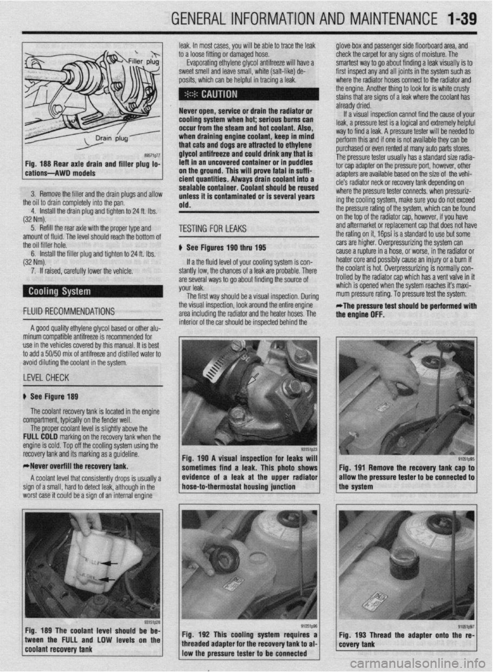
GENERALINFORMATIONAND MAINTENANCE 1-39
leak. In most cases, you will be able to trace the leak
to a loose fitting or damaged hose.
Evaporating ethylene glycol antifreeze will have a
sweet smell and leave small, white (salt-like) de-
oosits, which can be heloful in tracino a leak. glove box and passenger side floorboard area, and
check the carpet for any signs of moisture. The
smartest way to go about finding a leak visually is to
first inspect any and all joints in the system such as
where the radiator hoses connect to the radiator and
the engine. Another thing to look for is white crusty
stains that are signs of a leak where the coolant has
6. Install the filler plug and tighten to’24 ft. Ibs.
(32 Nm).
7. If raised, carefully lower the vehicle. amount of fluid. The level should ieach thk bottom of me rating on It, lap3 1s a danciara 10 use out some
the oil filler hole. A Qss
tin,t.as ran +tw,, 4liE cars are higher. Overpressurizing the system can
lose, or worse, in the radiator or
your cooling system is con- IIC~KI LUG MU PuaJbly cause an injury or a burn if
s of a leak are probable. There the coolant is hot. Overpressurizing is normally con-
WI” U”.VlUl ,.“,,I I” 9” about finding the source of trolled by the radiator cap which has a vent valve in it
your leak. which is opened when the system reaches it’s maxi-
The first wav should be a visual insnection. Durina mum pressure rating. To pressure test the system: 7 “1sl I ly”lsJa IJ” Wll” IJU
If a the fluid level of
stantly low, the chance cause a rupture in a I:
h.n+n. nrrrn nnA . . . . ..I.
FLUID RECOMMENDATIONS the visual inspection, look around the &tire engine -
area including the radiator and the heater hoses. The *The pressure test should be performed with
the enaine OFF.
A good quality ethylene glycol based or other alu-
minum compatible antifreeze is recommended for
use in the vehicles covered by this manual. It is best
to add a 50150 mix of antifreeze and distilled water to
avoid diluting the coolant in the system. interior of the car should be inspected behind the
LEVELCHECK
recovery tank and its marking as a guideline.
*Never overfill the recovery tank.
A coolant level that consistently drops is usually a
sign of a small, hard to detect leak, although in the
worst case it could be a sign of an internal engine “_y “,~--
1 Fia. 190 A visual insaection for leaks will 1
sometimes find a leak. This photo shows Fig. 191 Remove the recovery tank cap to
/ * ,, / evfdence of a leak at the upper radfator
* / /the system allow the pressure tester
to be connected to hose-to-thermostat housing junction
Fig. 189 The coolant level should be be-
1 coo,ant recovery tank tween the FULL and LOW levels on the
“‘~‘_I j Fig. 192 This cooling system requires a Fig. 193 Thread the adapter onto the re-
e’ffi1pg7 / g’051p96 / 1 covety tank threaded adapter for the recovery tank to al-
low the pressure tester to
be connected
Page 96 of 408
ENGINEANDENGINEOVERHAUL 3-35
Operating the engine without the proper
amount and type of engine oil will result in
severe engine damage.
33. Connect the negative battery cable and start
the engine.
34. Verify correct oil pressure
35. Inspect for leaks.
3.OL Engines
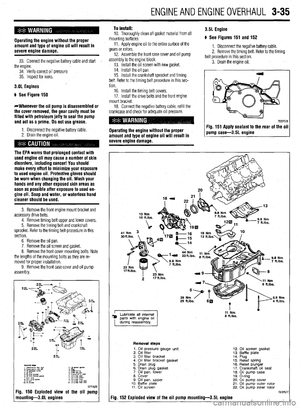
b See Figure 150
*Whenever the oil pump is disassembled or
the cover removed, the gear cavity must be
filled with petroleum jelly to seal the pump
and act as a prime. 00 not use grease.
1. Disconnect the negative battery cable.
2. Drain the engine oil.
The EPA warns that prolonged contact with
used engine oil may cause a number of skin
disorders, including cancer! You should
make every effort to minimize your exposure
to used engine oil. Protective gloves should
be worn when changing the oil. Wash your
hands and any other exposed skin areas as
soon as possible after exposure to used en-
gine oil. Soap and water, or waterless hand
cleaner should be used.
3. Remove the front engine mount bracket and
accessory drive belts.
4. Remove timing belt upper and lower covers.
5. Remove the timing belt and crankshaft
sprocket. Refer to the timing belt procedure in this
section.
6 Remove the oil pan.
7. Remove the oil screen and gasket.
8. Remove the front cover mounting bolts. Note
the lengths of the mounting bolts as they are re-
moved for proper installation.
9. Remove the front
assembly. and oil pump
9315393i 7g. 150 Exploded view of the oil pump
nounting-3.01 engines
To install:
10. Thoroughly clean all gasket material from all
mounting surfaces.
11. Apply engine oil to the entire surface of the
gears or rotors.
12. Assemble the front case cover and oil pump
assembly to the engine block.
13. Install the oil screen with new gasket.
14. Install the oil pan
15. Install the crankshaft sprocket and timing
belt. Refer to the timing belt procedure in this sec-
tion 3.5L Engine
p See Figures 151 and 152
1. Disconnect the negative battery cable.
2. Remove the timing belt. Refer to the timing
belt procedure in this section.
3. Drain the engine oil.
16. Install the timing belt covers.
17. Install the drive belts and the front engine
mount bracket.
18. Connect the negative battery cable, refill the
crankcase and check for adequate oil pressure.
Operating the engine without the proper
amount and type of engine oil will result in
severe engine damage. Fig. 151 Apply sealant to the rear of the oil
pump case-3.5L ermine
I 11 Nm
8 ft.lbs.
Removal steps
7g. 152 Exploded view of the oil pump mounting-3.51 engine
1. 011 pressure gauge unit
2. 011 filter
3. 011 filter bracket
4. 011 filter bracket gasket
5. Drain plug
6. Drawn plug gasket
7 011 lower pan,
8. Cover
9 011 pan, upper
10. Baffle date 11. 011 screen
12.
13.
14.
15.
16.
17.
10.
19.
20.
21.
22. Oil screen gasket
Baffle plate
Plug
Reltef spring
Relief plunger
Crankshaft oil seal
Oil pump case
0-ring
011 pump cover
011 pump outer rotor
011 pump inner rotor
Page 103 of 408
.
3-42 ENGINEANDENGINEOVERHAUL
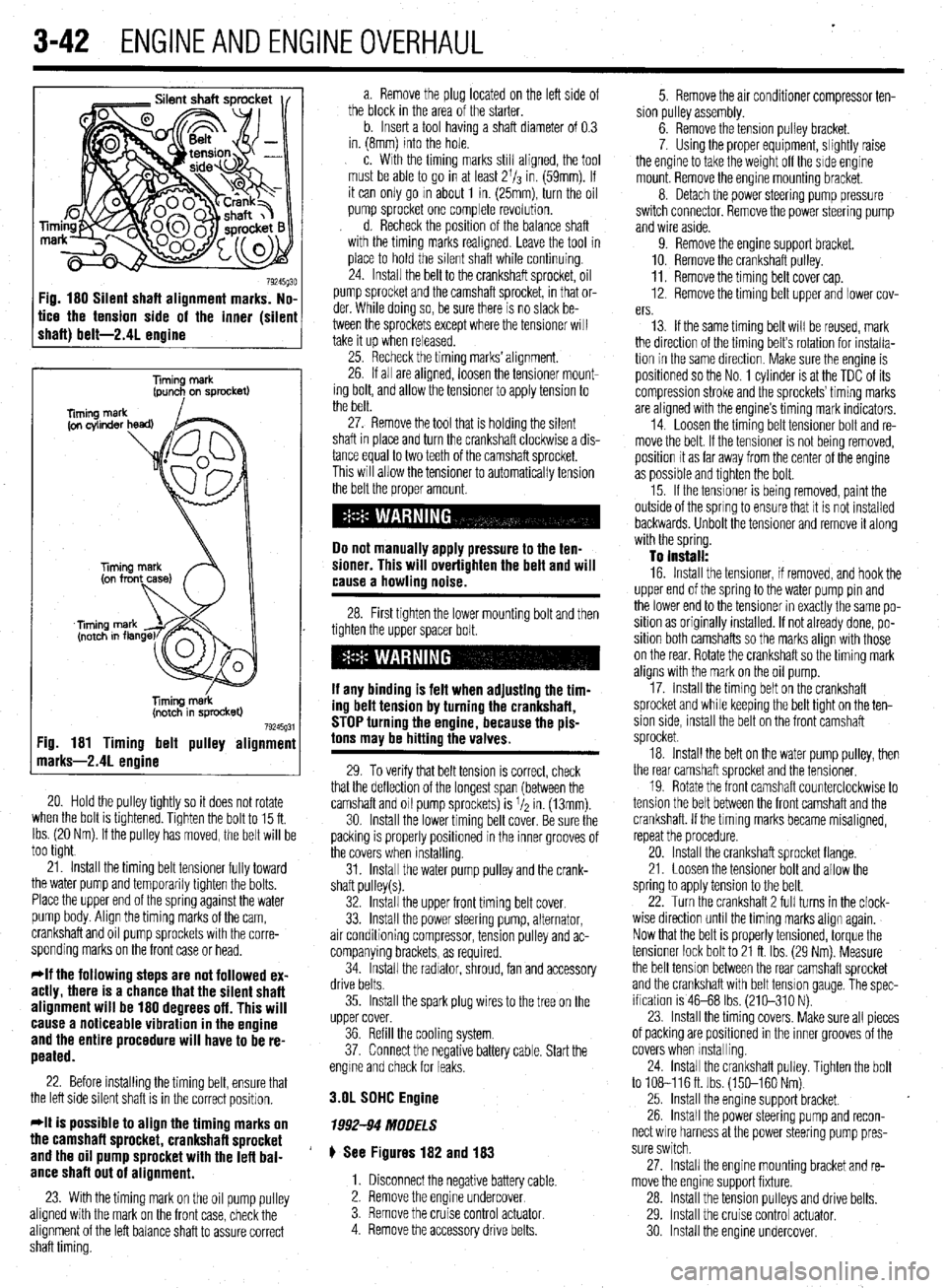
Fig. 180 Silent shaft alignment marks. No,
tice the tension side of the inner (silen
shaft) belt-2.41 enaine
Timing merk
(pun+ on sprocket)
liming m&k
(notch in sprocket)
79245g31 :ig. 181 Timing belt pulley alignmenl
narks-2.41 enoine
20. Hold the pulley tightly so it does not rotate
when the bolt is tlghtened. Tighten the bolt to 15 ft.
Ibs. (20 Nm). If the pulley has moved, the belt will be
too tight
21. Install the timing belt tensioner fully toward
the water pump and temporarily tighten the bolts.
Place the upper end of the spring against the water
pump body. Align the timing marks of the cam,
crankshaft and oil pump sprockets with the corre-
sponding marks on the front case or head.
*If the following steps are not followed ex-
actly, there is a chance that the silent shaft
alignment will be 180 degrees off. This will
cause a noticeable vibration in the engine
and the entire procedure will have to be re-
peated.
22. Before installing the timing belt, ensure that
the left side silent shaft is in the correct position.
*It is possible to align the timing marks on
the camshaft sprocket, crankshaft sprocket
and the oil pump sprocket with the lefl bal-
ance shaft out of alignment.
23. With the timing mark on the oil pump pulley
aligned with the mark on the front case, check the
alignment of the left balance shaft to assure correct
shaft timing. a. Remove the plug located on the left side of
the block in the area of the starter.
b. Insert a tool having a shaft diameter of 0.3
in. (8mm) into the hole.
c. With the timing marks still aligned, the tool
must be able to go in at least 2l/s in. (59mm). If
it can only go m about 1 in. (25mm), turn the oil
pump sprocket one complete revolution.
d. Recheck the position of the balance shaft
with the timing marks reahgned. Leave the tool in
place to hold the silent shaft while continuing.
24. Install the belt to the crankshaft sprocket, oil
pump sprocket and the camshaft sprocket, in that or-
der. While doing so, be sure there is no slack be-
tween the sprockets except where the tensioner will
take it up when released.
25. Recheck the timing marks’ alignment.
26. If all are aligned, loosen the tensioner mount-
ing bolt, and allow the tensioner to apply tension to
the belt.
27. Remove the tool that is holding the silent
shaft in place and turn the crankshaft clockwise a dis-
tance equal to two teeth of the camshaft sprocket.
This will allow the tensioner to automatically tension
the belt the proper amount.
Do not manually apply pressure to the ten-
sioner. This will overtighten the belt and will
cause a howling noise.
28. First tighten the lower mounting bolt and then
tighten the upper spacer bolt.
If any binding is felt when adiustino the tim-
ing delt tension by turning th;! crankshaft,
STOP turning the engine, because the pis-
tons may be hitting the valves.
29. To verify that belt tension is correct, check
that the deflection of the longest span (between the
camshaft and oil pump sprockets) is I/* in. (13mm).
30. Install the lower timing belt cover. Be sure the
packing is properly positioned in the inner grooves of
the covers when installing.
31. Install the water pump pulley and the crank-
shaft pulley(s).
32. Install the upper front timing belt cover.
33. Install the power steering pump, alternator,
air conditioning compressor, tension pulley and ac-
companying brackets, as required.
34. Install the radiator, shroud, fan and accessory
drive belts.
35. Install the spark plug wires to the tree on the
upper cover.
36. Refill the cooling system.
37. Connect the negative battery cable. Start the
engme and check for leaks.
3.OL SDHC Engine
1992-94 MODELS
# See Figures 182 and 183
1. Disconnect the negative battery cable.
2. Remove the engine undercover
3. Remove the cruise control
actuator 4. Remove the accessory drive belts. 5. Remove the air conditioner compressor ten-
sion pulley assembly.
6. Remove the tension pulley bracket.
7. Using the proper equipment, slightly raise
the engine to take the weight off the side engine
mount. Remove the engine mounting bracket.
8. Detach the power steering pump pressure
switch connector. Remove the power steering pump
and wire aside.
9. Remove the engine support bracket.
10. Remove the crankshaft pulley.
11. Remove the timing belt cover cap.
12. Remove the timing belt upper and lower cov-
ers.
13. If the same timing belt will be reused, mark
the direction of the timing belt’s rotation for installa-
tion in the same direction. Make sure the engine is
positioned so the No. 1 cylinder is at the TDC of its
compression stroke and the sprockets’ timing marks
are aligned with the engine’s timing mark indicators.
14. Loosen the timing belt tensioner bolt and re-
move the belt. If the tensioner is not being removed,
position it as far away from the center of the engine
as possible and tighten the bolt.
15. If the tensioner is being removed, paint the
outside of the spring to ensure that it is not installed
backwards. Unbolt the tensioner and remove it along
with the spring.
To install:
16. Install the tensioner, if removed, and hook the
upper end of the spring to the water pump pin and
the lower end to the tensioner in exactly the same po-
sition as originally installed. If not already done, po-
sition both camshafts so the marks align with those
on the rear. Rotate the crankshaft so the timing mark
aligns with the mark on the oil pump.
17. Install the timing belt on the crankshaft
sprocket and while keeping the belt tight on the ten-
sion side, install the belt on the front camshaft
sprocket.
18. Install the belt on the water pump pulley, then
the rear camshaft sprocket and the tensioner.
19. Rotate the front camshaft counterclockwise to
tension the belt between the front camshaft and the
crankshaft. If the tlmlng marks became misaligned,
repeat the procedure.
20. Install the crankshaft sprocket flange.
21. Loosen the tensioner bolt and allow the
spring to apply tension to the belt.
22. Turn the crankshaft 2 full turns in the clock-
wise direction until the timing marks align again.
Now that the belt is properly tensioned, torque the
tensioner lock bolt to 21 ft. Ibs. (29 Nm). Measure
the belt tension between the rear camshaft sprocket
and the crankshaft with belt tension gauge, The spec-
ification is 46-68 Ibs. (210-310 N).
23. Install the timing covers. Make sure all pieces
of packing are positioned in the inner grooves of the
covers when Installing.
24. install the crankshaft pulley. Tighten the bolt
to 108-116ft. Ibs. (150-160 Nm)
25. Install the engine support bracket.
26. Install the power steering pump and recon-
nect wire harness at the power steering pump pres-
sure switch.
27. Install the engine mounting bracket and re-
move the engine support fixture.
28. Install the tension pulleys and drive belts.
29. Install the cruise control actuator.
30 Install the engine undercover.
Page 128 of 408
ENGINEANDENGINEOVERHAUL 3-67
CONNECTING ROD
You should have the connecting rod checked for
StraiQhtness at a machine shop. If the connecting rod
is bent, it will unevenly wear the bearing and piston,
as well as place greater stress on these components.
Any bent or twisted connecting rods must be re-
placed. If the rods are straight and the wrist pin clear-
ance is within specifications, then only the bearing
end of the rod need be checked. Place the connecting
rod into a vice, with the bearing inserts in place, in-
stall the cap to the rod and torque the fasteners to
specifications. Use a telescoping gauge and carefully
measure the inside diameter of the bearings. Com-
pare this reading to the rods original crankshaft jour-
nal diameter measurement. The difference is the oil
clearance. If the oil clearance is not within specifica-
tions, install new bearings in the rod and take another
.
specifica- L
need to
shop as the pistons must be installed in the con measurement. it the Clearance is still out of :
tions, and the crankshaft is not, the rod will
be reconditioned by a machine shop.
*You can also use Plastigage’
@to check the
bearing clearances. The assen- . ...= - _______
Mm sectinn has complete instructions on its use.
Camshaft
Inspect the camshaft and lifters/followers as de
scribed earlier in this section.
Bearings
All of the enaine bearinos should be visuallv in-
~~~ I~ .- - -- ..-_-..,
spected for we; and/or damage. The bearing should
look evenly worn all around with no deep scores or
pits. If the bearing is severely worn, scored, pitted or
heat blued, then the bearing, and the components
that use it, should be brought to a machine shop for
block. ,ect
relationshipto the rod or engine damage can occur,
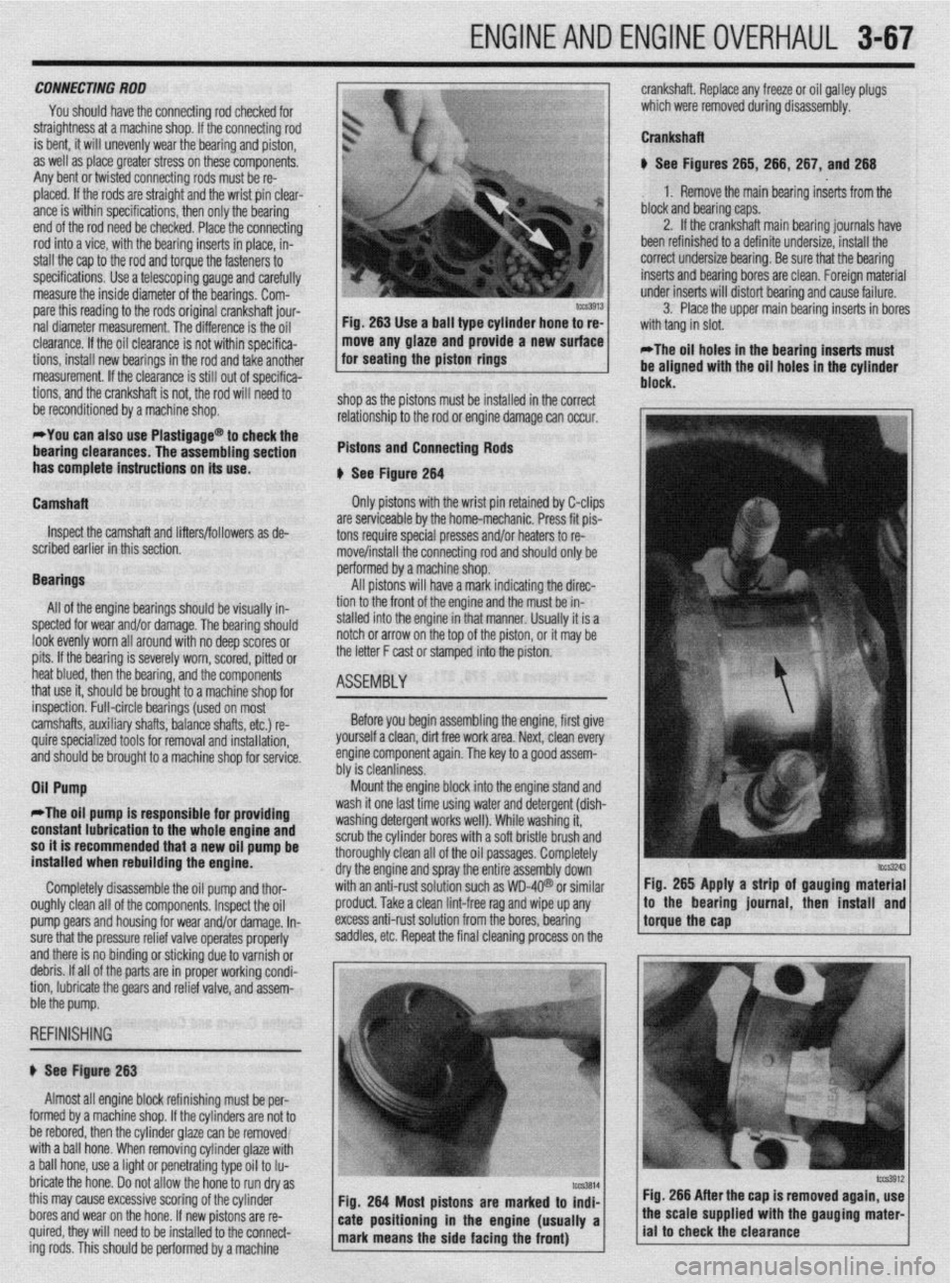
Pistons and Connecting Rods
I
b See Fiaute 264 --- --*------
Only pistons with the wrist pin retained by C-clips
are serviceable by the home-mechanic. Press fit pis-
tons require special presses and/or heaters to re- I”
rr
rove/install the connecting rod and should only be
PC srformed by a machine shop.
All pistons will have a mark indicating the direc-
tir 9n to the front of the engine and the must be in-
stalled into the engine in that manner. Usually it is a
notch or arrow on the top of the piston, or it may be
the letter F cast or stamped into the piston.
ASEtiBlY
1
crankshaft. Replace any freeze or oil galley plugs
which were removed during disassembly.
Crankshaft
u See Figures 265, 266, 267, and 266
1. Remove the main bearing inserts from the
block and bearing caps.
2. If the crankshaft main bearing journals have
been refinished to a definite undersize, install the
correct undersize bearina. Be sure that the bearina
inserts and bearing bores are clean. Foreign mateiial
under inserts will distort bearinq and cause failure.
3. Place the upper main bearing inserts in bores
*The oil holes in the bearing inserts must
be aligned with the oil holes in the cylinder
. . .
inspection. Full-circle bearings (used on most
camshafts, auxiliary shafts, balance shafts, etc.) re-
quire specialized tools for removal and installation, ’
and should be brought to a machine shop for service.
Oil Pump Before you begin assembling the engine, first give
yourself a clean, dirt free work area. Next, clean every
engine component again. The key to a QOOd assem-
hhr io da~nlinmw “‘I Ia ~rGiOllll,lc7.Ja. Mount the engine block into the engine stand and
II
*The oil pump is responsible fo
r providing wasn It one last time usmg water and detergent (dish-
unrhinn rldarnant ~nrirc well), While washing it, with a soft bristle brush and
: oil oassaoes. Comoletelv constant lubrication to the whole engine and 1ILl.M 0, ,y “GSGl ycx II ““1 n
so it is recommended that a new oil pump be scrub the cylinder bore:
installed when rebuilding the engine. thoroughly clean all oft
dry the engine and spra
Completely disassemble the oil pump and thor- with an anti-rust solutio
oughly clean all of the components. Inspect the oil
pro
pump Qears and housing for wear and/or damage. In- exe
sure that the pressure relief valve operates properly sac
and there is no binding or sticking due to varnish or
debris. If all of the parts are in proper working condi-
tion, lubricate the gears and relief valve, and assem-
r
j ht
y the entire assembly down’
in such as WD-4Q@ or similar Fig. 265 Apply a strip of gauging material
Iduct. Take a clean lint-free rag and wipe up any
less anti-rust solution from the bores, bearing
Idles, etc. Repeat the final cleaning process on the !torguethe~~p * ,’ / to the bearmg lournal, then mstall and
ble the pump.
REFINISHING
# See Figure 263
Almost all engine block refinishing must be per-
I
IUIIII~U uy a macnme snap. ir me cynnoers are nor ro
be rebored, then the cylinder glaze can be removed
with a ball hone. When removing cylinder glaze with
a ball hone, use a light or penetrating type oil to Iu-
bricate the hone. Do not allow the hone to run dry as
this may cause excessive scoring of the cylinder
bores and wear on the hone. If new pistons are re-
quired, they will need to be installed to the connect-
ing rods. This should be oerformed bv a machine Fig. 266 After the cap is removed again, use