1900 MITSUBISHI DIAMANTE tire pressure
[x] Cancel search: tire pressurePage 129 of 408
.
3-68 ENGINEANDENGINEOVERHAUL
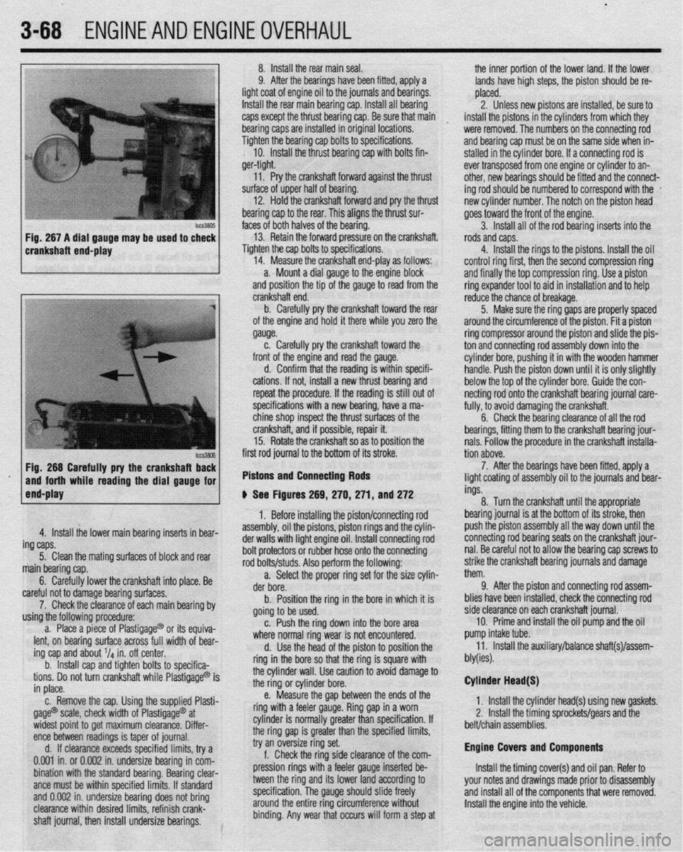
crankshaft end-play 8. Install the rear main seal.
the inner portion of the lower land. If the lower
9. After the bearings have been fitted, apply a
lands have high steps, the piston should be re-
light coat of engine oil to the journals and bearings.
placed.
Install the rear main bearing cap. Install all bearing
2. Unless new pistons are installed, be sure to
caps except the thiust bearing cap. Be sure that main
I
install the pistons in the cylinders from which they
bearing caps are installed in original locations.
were removed. The numbers on the connecting rod
Tighten the bearing cap bolts to specifications.
and bearing cap must be on the same side when in-
10. Install the thrust bearing cap with bolts fin-
stalled in the cylinder bore. If a connecting rod is
ger-tight.
ever transposed from one engine or cylinder to an-
11. Pry the crankshaft forward against the thrust
other, new bearings should be fitted and the connect-
surface of upper half of bearing.
ing rod should be numbered to correspond with the *
12. Hold the crankshaft forward and pry the thrust
new cylinder number. The notch on the piston head
bearing cap to the rear. This aligns the thrust sur-
goes toward the front of the engine.
faces of both halves of the bearing.
3. Install all of the rod bearing inserts into the
13. Retain the forward pressure on the crankshaft.
rods and caps.
Tighten the cap bolts to specifications.
4. Install the rings to the pistons. Install the oil
14. Measure the crankshaft end-play as follows:
control ring first, then the second compression ring
a. Mount a dial gauge to the engine block
and finally the top compression ring. Use a piston
and position the tip of the gauge to read from the
ring expander tool to aid in installation and to help
Fig. 266 Carefully pry the crankshafl Ez
and forth while reading the dial gauge for
end-play first rod journal to the bottom of its stroke.
Pistons and Connecting Rods
4. Install the lower main bearing inserts in bear-
ing caps.
5. Clean the mating surfaces of block and rear
main bearing cap.
6. Carefully lower the crankshaft into place. Be
careful not to damage bearing surfaces.
7. Check the clearance of each main bearing by
using the following procedure:
a. Place a piece of Plastigage@ or its equiva-
lent, on bearing surface across full width of bear-
ing cap and about V4 in. off center.
b. Install cap and tighten bolts to specifica-
tions. Do not turn crankshaft while Plastigage@ is
in place.
c. Remove the cap. Using the supplied Plasti-
gage@ scale, check width of Plastigage@ at
widest point to get maximum clearance. Differ-
ence between readings is taper of journal.
d. If clearance exceeds specified limits, try a
0.001 in. or 0.002 in. undersize bearing in com-
bination with the standard bearing. Bearing clear-
ante must be within specified limits. If standard
and 0.002 in. undersize bearing does not bring
clearance within desired limits, refinish crank-
shaft journal, then install undersize bearings. crankshaft end.
b. Carefully pry the crankshaft toward the rear
of the engine and hold it there while you zero the
gauge.
c. Carefully pry the crankshaft toward the
front of the engine and read the gauge.
d. Confirm that the reading is within specifi-
cations. If not, install a new thrust bearing and
repeat the procedure. If the reading is still out of
specifications with a new bearing, have a ma-
chine shop inspect the thrust surfaces of the
crankshaft, and if possible, repair it.
15. Rotate the crankshaft so as to position the
# See Figures 269, 270,271, and 272
1. Before installing the piston/connecting rod
assembly, oil the pistons, piston rings and the cylin-
der walls with light engine oil. Install connecting rod
bolt protectors or rubber hose onto the connecting
rod bolts/studs. Also perform the following:
a. Select the proper ring set for the size cylin-
der bore.
b. Position the ring in the bore in which it is
going to be used.
c. Push the ring down into the bore area
where normal ring wear is not encountered.
d. Use the head of the piston to position the
ring in the bore so that the ring is square with
the cylinder wall. Use caution to avoid damage to
the ring or cylinder bore.
e. Measure the gap between the ends of the
ring with a feeler gauge. Ring gap in a worn
cylinder is normally greater than specification. If
the ring gap is greater than the specified limits,
try an oversize ring set.
f. Check the ring side clearance of the com-
pression rings with a feeler gauge inserted be-
tween the ring and its lower land according to
specification. The gauge should slide freely
around the entire ring circumference without
binding. Any wear that occurs will form a step at reduce the chance of breakage.
5. Make sure the ring gaps are properly spaced
around the circumference of the piston. Fit a piston
ring compressor around the piston and slide the pis-
ton and connecting rod assembly down into the
cylinder bore, pushing it in with the wooden hammer
handle. Push the piston down until it is only slightly
below the top of the cylinder bore. Guide the con-
netting rod onto the crankshaft bearing journal care-
fully, to avoid damaging the crankshaft.
6. Check the bearing clearance of all the rod
bearings, fitting them to the crankshaft bearing jour-
nals. Follow the procedure in the crankshaft installa-
tion above.
7. After the bearings have been fitted, apply a
light coating of assembly oil to the journals and bear-
ings.
8. Turn the crankshaft until the appropriate
bearing journal is at the bottom of its stroke, then
push the piston assembly all the way down until the
connecting rod bearing seats on the crankshaft jour-
nal. Be careful not to allow the bearing cap screws to
strike the crankshaft bearing journals and damage
them.
9. After the piston and connecting rod assem-
blies have been installed, check the connecting rod
side clearance on each crankshaft journal.
10. Prime and install the oil pump and the oil
pump intake tube.
11. Install the auxiliary/balance shaft(s)/assem-
bly(ies).
Cylinder Head(S)
1. Install the cylinder head(s) using new gaskets.
2, Install the timing sprockets/gears and the
belt/chain assemblies.
Engine Covers and Components
Install the timing cover(s) and oil pan. Refer to
your notes and drawings made prior to disassembly
and install all of the components that were removed.
Install the engine into the vehicle.
Page 193 of 408
install the line to the fuel rail. Tighten the mounting
bolts,
19. Attach the PCV hose and the breather hose if
thev were disconnected.
20. Connect the negative battery cable. Pressur-
ize the fuel system and inspect all connections for
I
leaks.
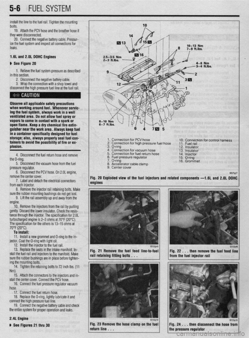
1.6L and 2.01 DOHC Engines
b See Figure 20
1. Relieve the fuel system pressure as described
in this section.
2. Disconnect the negative battery cable.
3. Wrap the connection with a shop towel and
disconnect the high pressure fuel line at the fuel rail.
Observe all applicable safety precautions
when working around fuel. Whenever servic-
ing the fuel system, always work in a well
ventilated area. Do not allow fuel spray or
vapors to come in contact with a spark or
open flame. Keep a dry chemical fire extin-
guisher near the work area. Always keep fuel
in a container specifically designed for fuel
storage; also, always properly seal fuel con-
* tainers to avoid the possibility of fire or ex-
plosion.
4. Disconnect the fuel return hose and remove
the O-ring.
5. Disconnect the vacuum hose from the fuel
pressure regulator.
6. Disconnect the PCV hose. On 2.OL engine,
remove the center cover.
1 x Connection for PCV hose
2. Connection for high pressure fuel hose
3. O-ring
4. Connection for vacuum hose
5. Connection for fuel return hose
&2 I=, 1c.1 nrncc*.ra regu,ator
lble clamD
7. Label and detach the electrical connectors
from each iniector.
8. Accelerator ca
9. Center cover . 10. Connection for control harness
11 Fuel rail
12. Insulator
13. Insulator
14. Injector
15. O-ring
16. Grommet
89575g27 Exploded view of the fuel injectors and related
components -1.6L and 2.QL DOHC
5-6 FUELSYSTEM
8. Remove the injector rail retaining bolts, Make
sure the rubber mounting bushings do not get lost.
9. Lift the rail assembly up and away from the
engine.
10. Remove the injectors from the rail by pulling
gently. Discard the lower insulator. Check the resis-
tance through the injector. The specification for 2.OL
turbocharged engine is 2-3 ohms at 70°F (20°C).
The specification for the others is 13-15 ohms at
70°F (20°C). To install:
11. Install a new grommet and O-ring to the in-
jector. Coat the O-ring with light oil.
12. install the injector to the fuel rail.
13. Replace the seats in the intake manifold. In-
stall the fuel rail and injectors to the manifold. Make
sure the rubber bushings are in place before tighten-
ing the mounting bolts.
14. Tighten the retaining bolts to 72 inch lbs. (11
Nm).
Fig. 21 Remove the fuel feed line-to-fuel
rail retaining fitting bolts . . .
15. Attach the connectors to the injectors and in-
stall the center cover. Connect the PCV hose.
16. Connect the fuel pressure regulator vacuum
hose.
17. Connect the fuel return hose.
18. Replace the O-ring, lightly lubricate it and
connect the high pressure fuel line.
19. Connect the negative battery cable and check
the entire system for proper operation and leaks. Fig. 22 . . . then remove the fuel feed line
from the fuel injector rail
2.4L Engine
b See Figures 21 thru 30
Page 195 of 408
5-8 FUELSYSTEM
9 ,npimr w1m.m
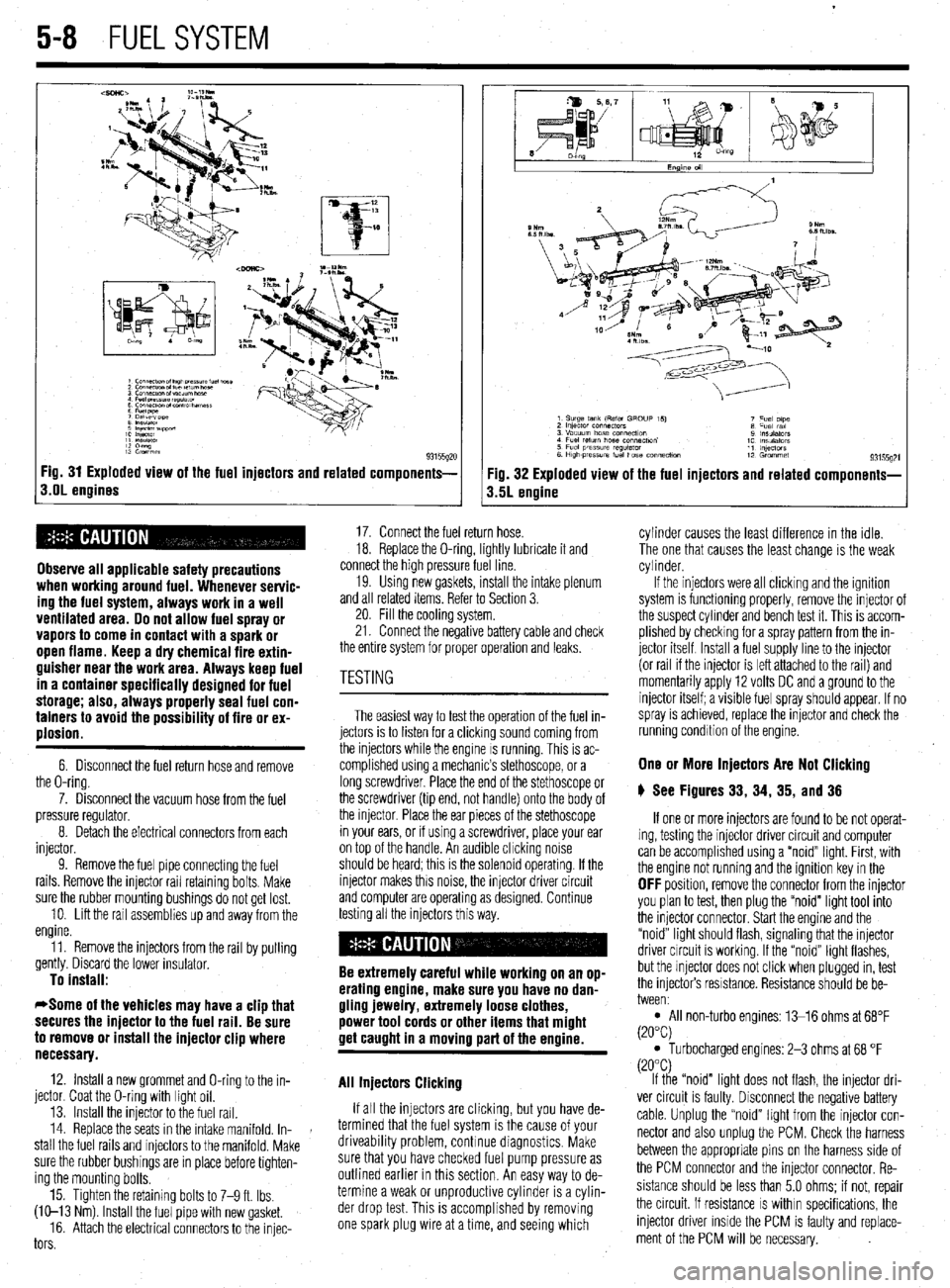
1: i”“L,
1: 82”w
93155gx Fig. 31 Exploded view of the fuel injectors and related components-
s.OL engines
Observe all applicable safety precautions
when working around fuel. Whenever servic-
ing the fuel system, always work in a well
ventilated area. Do not allow fuel spray or
vapors to come in contact with a spark or
open flame. Keep a dry chemical fire extin-
guisher near the work area. Always keep fuel
in a container specifically designed for fuel
storage; also, always properly seal fuel con-
tainers to avoid the possibility of fire or ex-
plosion.
6. Disconnect the fuel return hose and remove
the O-ring.
7. Disconnect the vacuum hose from the fuel
pressure regulator.
8. Detach the electrical connectors from each
injector.
9. Remove the fuel pipe connectmg the fuel
rails. Remove the injector rail retaining bolts. Make
sure the rubber mounting bushings do not get lost.
10. Lift the rail assemblies up and away from the
engine.
11. Remove the injectors from the rail by pulling
gently. Discard the lower insulator.
To install:
*Some of the vehicles may have a clip that
secures the injector to the fuel rail. Be sure
to remove or install the injector clip where
necessary.
12. Install a new grommet and O-ring to the in-
jector. Coat the O-ring with light oil.
13. Install the injector to the fuel rail.
14. Replace the seats in the intake manifold. In-
stall the fuel rails and injectors to the manifold. Make
sure the rubber bushings are in place before tighten-
ing the mounting bolts.
15. Tighten the retaining bolts to 7-9 ft. Ibs.
(W-13 Nm) Install the fuel pipe with new gasket.
16. Attach the electrical connectors to the injec-
tors
Fig. 32 Exploded view of the fuel injectors and related components-
3.5L engine
17. Connect the fuel return hose.
18. Replace the O-ring, lightly lubricate it and
connect the high pressure fuel line.
19. Usmg new gaskets, install the intake plenum
and all related items. Refer to Section 3.
20. Fill the cooling system.
21. Connect the negative battery cable and check
the entire system for proper operation and leaks.
The easiest way to test the operation of the fuel in-
jectors is to listen for a clicking sound coming from
the injectors while the engine IS running. This is ac-
complished using a mechanic’s stethoscope, or a
long screwdriver. Place the end of the stethoscope or
the screwdriver (tip end, not handle) onto the body of
the injector. Place the ear pieces of the stethoscope
in your ears, or if using a screwdriver, place your ear
on top of the handle. An audible chcking noise
should be heard; this is the solenoid operating. If the
injector makes this noise, the injector driver circuit
and computer are operating as designed. Continue
testing all the injectors this way.
Be extremely careful while working on an op-
erating engine, make sure you have no dan-
gling jewelry, extremely loose clothes,
power tool cords or other items that might
get caught in a moving part of the ermine.
All Injectors Clicking
If all the injectors are clicking, but you have de-
termined that the fuel system is the cause of your
driveability problem, continue diagnostics. Make
sure that you have checked fuel pump pressure as
outlined earlier in this section. An easy way to de-
termine a weak or unproductive cylinder is a cylin-
der drop test. This is accomplished by removing
one spark plug wire at a time, and seeing which cylinder causes the least difference in the idle.
The one that causes the least change is the weak
cylinder.
If the injectors were all clicking and the ignition
system is functioning properly, remove the injector of
the suspect cylinder and bench test it. This is accom-
plished by checking for a spray pattern from the in-
jector itself Install a fuel supply line to the injector
(or rail if the injector is left attached to the rail) and
momentarily apply 12 volts DC and a ground to the
injector itself; a visible fuel spray should appear. If no
spray is achieved, replace the injector and check the
running condition of the engine.
One or More Injectors Are Not Clicking
6 See Figures 33, 34, 35, and 36
If one or more injectors are found to be not operat-
ing, testing the injector driver circuit and computer
can be accomplished using a “noid” light. First, with
the engine not running and the ignition key in the
OFF position, remove the connector from the injector
you plan to test, then plug the “noid” light tool into
the injector connector. Start the engine and the
“noid” light should flash, signaling that the injector
driver circuit is working. If the “noid” light flashes,
but the injector does not click when plugged in, test
the injectors resistance. Resistance should be be-
tween:
l All non-turbo engines: 13-16 ohms at 68°F
(20°C)
l Turbocharged engines: 2-3 ohms at 68 “F
(20°C)
If the “noid” light does not flash, the injector dri-
ver circuit is faulty. Disconnect the negative battery
cable. Unplug the “noid” light from the injector con-
nector and also unplug the PCM. Check the harness
between the appropriate pins on the harness side of
the PCM connector and the injector connector. Re-
sistance should be less than 5.0 ohms; if not, repair
the circuit. If resistance
IS within specifications, the
injector driver inside the PCM is faulty and replace-
ment of the PCM will be necessary.
Page 197 of 408
5-10 FUELSYSTEM
1. _
Fuel tank pressure
-
relef vdive
REMOVAL &INSTALLATION
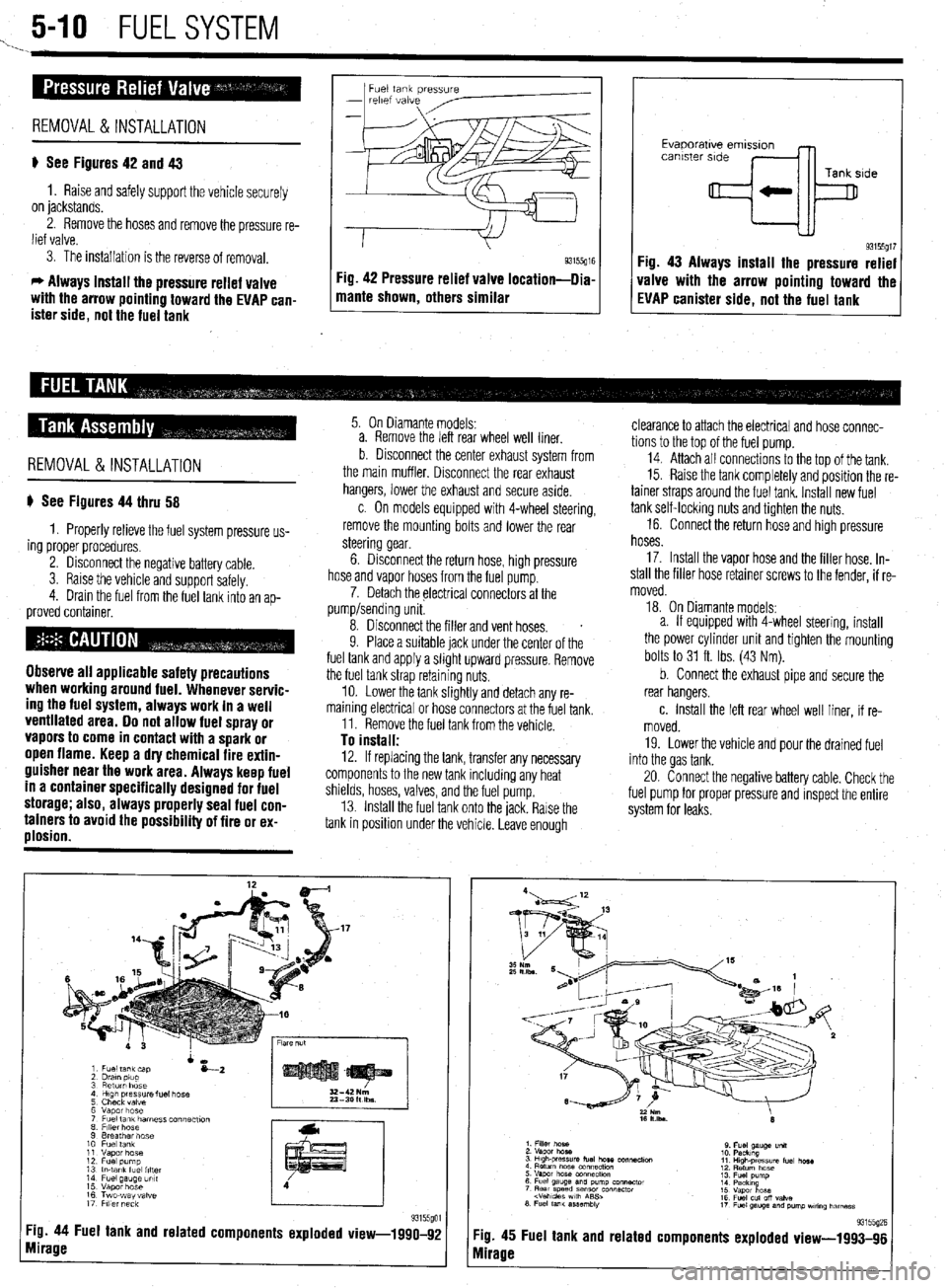
p See Figures 42 and 43
1. Raise and safely support the vehicle securely
on jackstands.
2. Remove the hoses and remove the pressure re-
lief valve.
3. The installation is the reverse of removal.
c, Always install the pressure relief valve
with the arrow pointing toward the EVAP can-
ister side, not the fuel tank 1 mame shown, others similar g3155g” Fig 42 Pressure relief valve location-llia
I I
Evaporatwe emlsslon
canister side
Tank side
+k
93155gt7 Fig. 43 Always install the pressure relief
valve with the arrow pointing toward the
EVAP canister side, not the fuel tank
REMOVAL&INSTALLATION
p See Figures 44 thru 58
1. Properly relieve the fuel system pressure us-
ing proper procedures.
2. Disconnect the negative battery cable.
3. Raise the vehicle and support safelv.
4. Drain the fuel from the fuel tank into an
ap- proved container.
Observe all applicable safety precautions
when working around fuel. Whenever servic-
ing the fuel system, always work in a well
ventilated area. Do not allow fuel spray or
vapors to come in contact with a spark or
open flame. Keep a dry chemical fire extin-
guisher near the work area. Always keep fuel
in a container specifically designed for fuel
storage; also, always properly seal fuel con-
tainers to avoid the possibility of fire or ex-
plosion.
5. On Diamante models:
a. Remove the left rear wheel well liner.
b Disconnect the center exhaust system from
the main muffler. Disconnect the rear exhaust
hangers, lower the exhaust and secure aside.
c. On models equipped with 4-wheel steering,
remove the mounting bolts and lower the rear
steering gear.
6. Disconnect the return hose, high pressure
hose and vapor hoses from the fuel pump.
7. Detach the electrical connectors at the
pump/sending unit.
8. Disconnect the filler and vent hoses.
s
9. Place a suitable jack under the center of the
fuel tank and apply a slight upward pressure. Remove
the fuel tank strap retaining nuts.
10. Lower the tank slightly and detach any re-
maining electrical or hose connectors at the fuel tank.
11. Remove the fuel tank from the vehicle.
To install: 12. If replacing the tank, transfer any necessary
components to the new tank including any heat
shields, hoses, valves, and the fuel pump.
13. Install the fuel tank onto the jack. Rarse the
tank in position under the vehicle. Leave enough
Tg. 44 Fuel tank and related components exploded view-1990-92
mirage
clearance to attach the electrical and hose connec-
tions to the top of the fuel pump.
14. Attach all connectrons to the top of the tank.
15. Raise the tank completely and position the re-
tainer straps around the fuel tank. Install new fuel
tank self-locking nuts and tighten the nuts.
16. Connect the return hose and high pressure
hoses.
17. Install the vapor hose and the filler hose. In-
stall the filler hose retainer screws to the fender, if re-
moved.
18. On Diamante models:
a. If equipped with 4-wheel steering, install
the power cylinder unit and tighten the mounting
bolts to 31 ft. Ibs. (43 Nm).
b. Connect the exhaust pipe and secure the
rear hangers.
c. Install the left rear wheel well liner, if re-
moved.
19. Lower the vehicle and pour the drained fuel
into the gas tank.
20. Connect the negative battery cable. Check the
fuel pump for proper pressure and inspect the entire
system for leaks.
:ig. 45
vlirage Fuel tank and related 93155(12E components exploded view-1993-96
Page 199 of 408
5-12 FUELSYSTEM
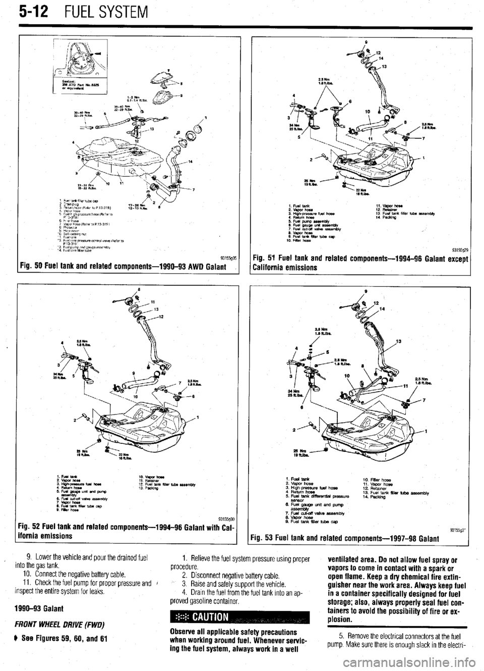
Fig. 50 Fuel tank and related components-1990-93 AWD Galant
:ig. 52 Fuel tank and related components-1994-96 Galant with Cal-
fornia emissions
9. Lower the vehicle and pour the drained fuel
into the gas tank. 1. Relieve the fuel system pressure using proper
procedure. ventilated area. Do not allow fuel spray or
10. Connect the negative battery cable.
11. Check the fuel pump for proper pressure and 2. Disconnect negative battery cable. vapors to come in contact with a spark or
J
inspect the entire system for leaks, 3. Raise and safely support the vehicle. open flame. Keep a dry chemical fire extin-
4. Drain the fuel from the fuel tank Into an ap- guisher near the work area. Always keep fuel
in a container specifically designed for fuel
1990-93 Galant
FRONT WHEEL DRIVE (FWD)
e See Figures 59, 60, and 61
proved gasoline container. storage; also, always properly seal fuel con-
tainers to avoid the possibility of fire or ex-
plosion.
Observe all applicable safety precautions
when working around fuel. Whenever servic-
ing the fuel system, always work in a well
5. Remove the electrical connectors at the fuel
pump. Make sure there is enough slack in the electri-
Page 201 of 408
.
5-14 FUEL SYSTEM
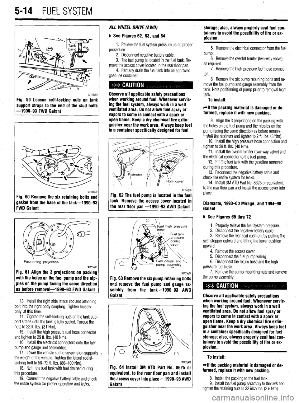
93155(10: ‘ig. 59 loosen self-locking nuts on tank
mpporf straps to the end of the stud bolts
-1990-93 FWD Galant
93i55Qo$ :ig. 60 Remove the six retaining bolts and
lasket from the base of the tank-1990-93
:WD Galant
Q m
0 a
cl@=
u a-
a al2
0
0
Q
a a
Posmdmng projectton 93155910 Fig. 61 Align the 3 projections on packing
with the holes on the fuel pump and the nip-
ples on the pump facing the same direction
as before removal-1990-93 FWD Galant
13. Install the right side lateral rod and attaching
bolt into the right body coupling. Tighten loosely
only, at this time.
14. Tighten the self-locking nuts on the tank sup-
port straps until the tank is fully seated. Torque the
nuts to 22 ft. Ibs. (31 Nm).
15. Install the high pressure fuel hose connector
and tighten to 29 ft. Ibs. (40 Nm).
16. Install the electrical connectors onto the fuel
pump and gauge unit assemblies.
17. Lower the vehicle so the suspension supports
the weight of the vehicle. Tighten the lateral rod at-
taching bolt to 58-72 ft Ibs. (So-100 Nm).
18. Refill the fuel tank with fuel drained during
this procedure.
19. Connect the negative battery cable and check
the entire system for proper operation and leaks. ALL WHEEL DRIVE (A WO)
# See Figures 62, 63, and 64
1. Relieve the fuel system pressure using proper
procedure.
2. Disconnect negative battery cable.
3. The fuel pump is located in the fuel tank. Re-
move the access cover located in the rear floor pan
4 Parbally drain the fuel tank into an approved
gasoline container.
Observe all applicable safety precautions
when workina around fuel. Whenever servic-
ing the fuel system, always work in a well
ventilated area. Do not allow fuel spray or
vapors to come in contact with a spark or
open flame. Keep a dry chemical fire extin-
guisher near the work area. Always keep fuel
in a container specifically designed for fuel
-ig. 62 The fuel pump is located in the fuel
r
ank. Remove the access cover located m
he rear floor pan -1990-93 AWD Galant
93155go7 Fig. 63 Remove the six pump retaining bolts
and remove the fuel pump and gauge as-
sembly from the tank-1990-93 AWD
1 Galant
93155goa Fig. 64 Install 3M ATD Part No. 8625 or
equivalent, to the rear floor pan and install
ihe access cover into place -1990-93 AWD
Ealant storage; also, always properly seal fuel con-
tainers to avoid the possibility of fire or ex-
plosion.
5 Remove the electrical connector from the fuel
pump.
6. Remove the overfill limiter (two-way valve),
as required.
7. Remove the high pressure fuel hose connec-
tor.
8. Remove the six pump retaming bolts and re-
move the fuel pump and gauge assembly from the
tank. Note positioning of pump prior to removal from
tank.
To install:
*If the packing material is damaged or de-
formed, replace it with new packing.
9. Align the 3 projections on the packing with
the holes on the fuel pump and the nipples on the
pump facmg the same direction as before removal.
Install the retainers and tlghten to 2 ft. Ibs. (3 Nm).
10. Install the high pressure hose connection and
tighten to 29 ft. Ibs. (40 Nm).
11. Install the overfill limiter (two-way valve) and
the electrical connector to the fuel pump.
12. Fill the fuel tank with the gasoline removed
during this procedure.
13. Reconnect the negative battery cable and
check the entire system for leaks.
14. Install 3M ATD Part No. 8625 or equivalent,
to the rear floor pan and install the access cover into
place.
Diamante, 1993-00 Mirage, and 1994-98
Galant
# See Figures 65 thru 72
1. Properly relieve the fuel system pressure.
2. Disconnect the negative battery cable.
3. Remove the rear seat cushion, by pulling the
seat stopper outward and lifting the lower cushion
upward.
4. Remove the access cover.
5. Disconnect the fuel pump wiring.
6. Disconnect the return hose and the high
pressure fuel hose.
7. Remove the pump mounting nuts and remove
the pump assembly.
Observe all applicable safety precautions
when working around fuel. Whenever servic-
ing the fuel system, always work in a well
ventilated area. Do not allow fuel spray or
vapors to come in contact with a spark or
open flame. Keep a dry chemical fire extin-
guisher near the work area. Always keep fuel
in a container specifically designed for fuel
storage; also, always properly seal fuel con-
tainers to avoid the possibility of fire or ex-
plosion.
To install:
rlf the packing material is damaged or de-
formed, replace it with new packing.
8. Install the packing to the fuel tank.
9. Install the fuel pump assembly to the tank and
tighten the retaining nuts to 22 inch Ibs. (2 5 Nm).
Page 202 of 408
FUELSYSTEM 5-15
*Tilt the float to the left of the vehicle, when
installing the pump assembly..
10. Connect the high pressure hose, return hose
and the fuel tank wiring.
11. Connect the negative battery cable.
12. Check the fuel pump for proper pressure and
inspect the entire system for leaks.
13. Apply sealant to the access cover and install
the cover.
14. Install the rear seat cushion.
1999-M Galant
b See Figures 65 thru 75 ’
1. Properly relieve the fuel system pressure.
2. Disconnect the negative battery cable.
3. Remove the rear seat cushion, by pulling the
seat stopper outward and lifting the lower cushion
upward.
4. Remove the access cover.
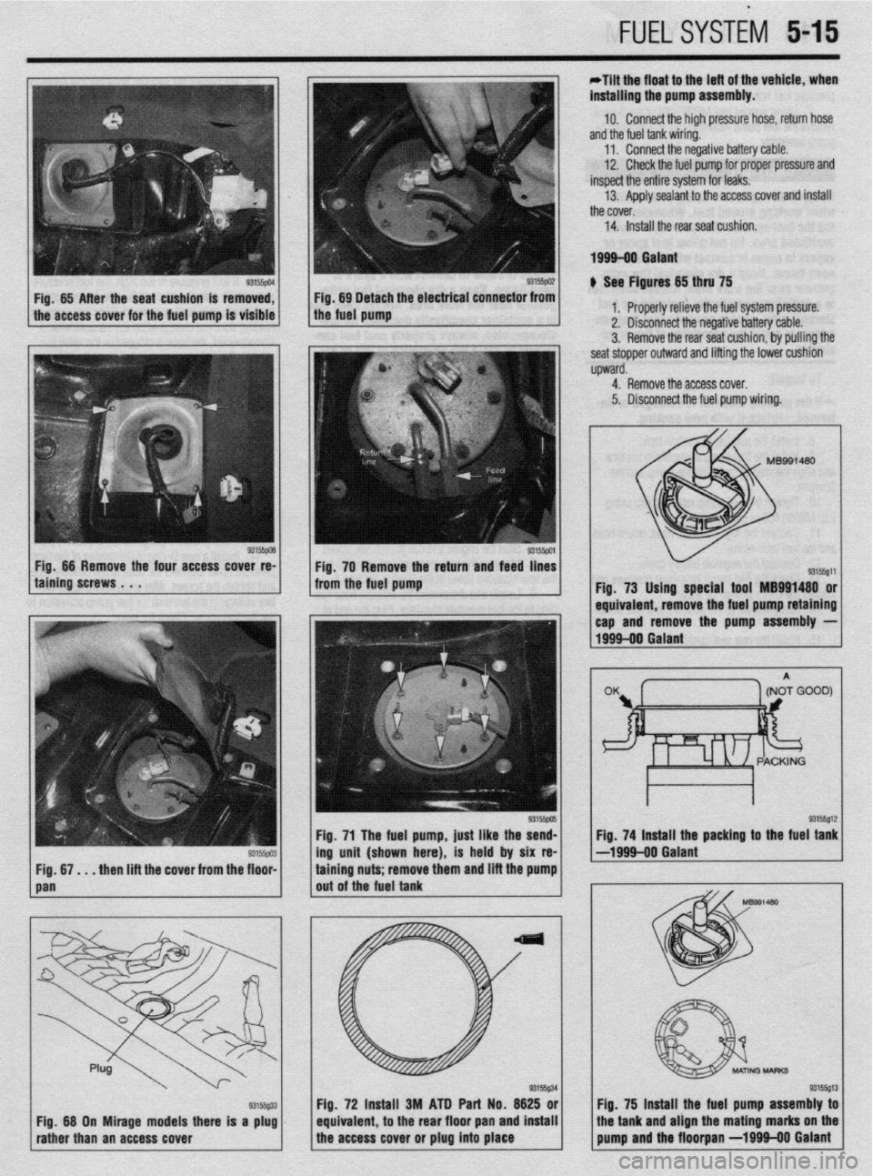
Fig. 73 Using special tool MB991480 or
1 equivaler It, remove the fuel pump retaining
I I
Fig. 71 The fuel pump, just like the send- Fig. 74 Install the packing to the fuel tank
-- 93155~03 ing unit (shown here), is held by six re- -1999-00 Galant
. _. ._. .
-. m and lift the pump
. . . then lift the cover from tne floor- tammg nuts; remove tne
out of the fuel tank
J I A/ -p,486
I
Fig. 75 lnsta
, II the fuel pump assembly toi
equivalent 72 Ins$ll 3M ATD Part No. 6625 ori /’
to the rear floor pan and install the tank and align the mating marks on the
the access cover or plug into place pump and the floorpan -1999110 Galant Fig, 68 On Mirage models there is a plug
rather than an access cover
Page 203 of 408
.
5-16 FUELSYSTEM
6. Disconnect the return hose and the high
pressure fuel hose.
7. Using special tool MB991480 or equivalent,
remove the fuel pump retaining cap and remove the
pump assembly.
Observe all applicable safety precautions
when working around fuel. Whenever servic-
ing the fuel system, always work in a well
ventilated area. Do not allow fuel spray or
vapors to come in contact with a spark or
open flame. Keep a dry chemical fire extin-
guisher near the work area. Always keep fuel
in a container specifically designed for fuel
storage; also, always properly seal fuel con-
tainers to avoid the possibility of fire or ex-
plosion.
To install:
*If the packing material is damaged or de-
formed, replace it with new packing.
8. Install the packing to the fuel tank.
9. Install the fuel pump assembly to the tank
and align the mating marks on the pump and the
floorpan.
10. Tighten the fuel pump retaining cap using
tool MB991480 or equrvalent.
11. Connect the high pressure hose, return hose
and the fuel tank wirmg.
12. Connect the negative battery cable.
13. Check the fuel pump for proper pressure and
inspect the entire system for leaks.
14. Apply sealant to the access cover and install
the cover.
15. Install the rear seat cushion.
TESTING
1. Relieve fuel system pressure.
2. Disconnect the battery negative cable.
3. Disconnect the fuel hrgh pressure hose at the
delivery pipe side.
Observe all applicable safety precautions
when working around fuel. Whenever servic-
ing the fuel system, always work in a well
ventilated area. Do not allow fuel spray or
vapors to come in contact with a spark or
open flame. Keep a dry chemical fire extin-
guisher near the work area. Always keep fuel
in a container specifically designed for fuel
storage; also, always properly seal fuel con-
tainers to avoid the possibility of fire or ex-
alosion.
4. Connect a fuel pressure gauge to tools
MD998709 and MD998742 or exact equivalent, with
appropriate adapters, seals and/or gaskets to prevent
leaks during the test. Install the gauge and adapter
between the delivery pipe and high pressure hose. In-
stall carefully to prevent leaks.
5. Connect the negative battery cable.
6. Apply battery voltage to the terminal for fuel
pump activation (located in the engine compartment)
to run the fuel pump, and check for leaks.
7. Start the engine and run at curb idle speed.
8. Measure the fuel pressure and compare to
the specifications listed in the chart in Section 1.
9. Locate and disconnect the vacuum hose run-
ning to the fuel pressure regulator. Plug the end of
the hose and record the fuel pressure again. The fuel
pressure should have increased approximately IO
psi. 10. Reconnect the vacuum hose the fuel pressure
regulator. After the fuel pressure stabilizes, race the
engine 2-3 times and check that the fuel pressure
does not fall when the engine is running at idle.
il. Check to be sure there is fuel pressure in the
return hose by gently pressing the fuel return hose
with fingers while racing the engine. There will be no
fuel pressure in the return hose when the volume of
fuel flow is low.
12. If fuel pressure is too low, check for a
clogged fuel filter, a defective fuel pressure regulator
or a defective fuel pump, any of which will require re-
placement.
13. If fuel pressure is too high, the fuel pressure
regulator is defective and will have to be replaced or
the fuel return is bent or clogged. If the fuel pressure
readmg does not change when the vacuum hose is
disconnected, the hose is clogged or the valve is
stuck in the fuel pressure regulator and it will have to
be replaced.
14. Stop the engine and check for changes in the
fuel pressure gauge. It should not drop. If the gauge
reading does drop, watch the rate of drop. If fuel
pressure drops slowly, the likely cause is a leaking
injector which will require replacement. If the fuel
pressure drops immediately after the engine is
stopped, the check valve in the fuel pump isn’t clos-
ing and the fuel pump will have to be replaced.
15. Relieve fuel system pressure.
16. Disconnect the high pressure hose and re-
move the fuel pressure gauge from the delivery pipe.
17. Install a new O-ring in the groove of the high
pressure hose. Connect the hose to the delivery pipe
and tighten the screws. After Installation, apply bat-
tery voltage to the terminal for fuel pump activation to
run the fuel pump. Check for leaks.