1900 MITSUBISHI DIAMANTE tire pressure
[x] Cancel search: tire pressurePage 295 of 408
.
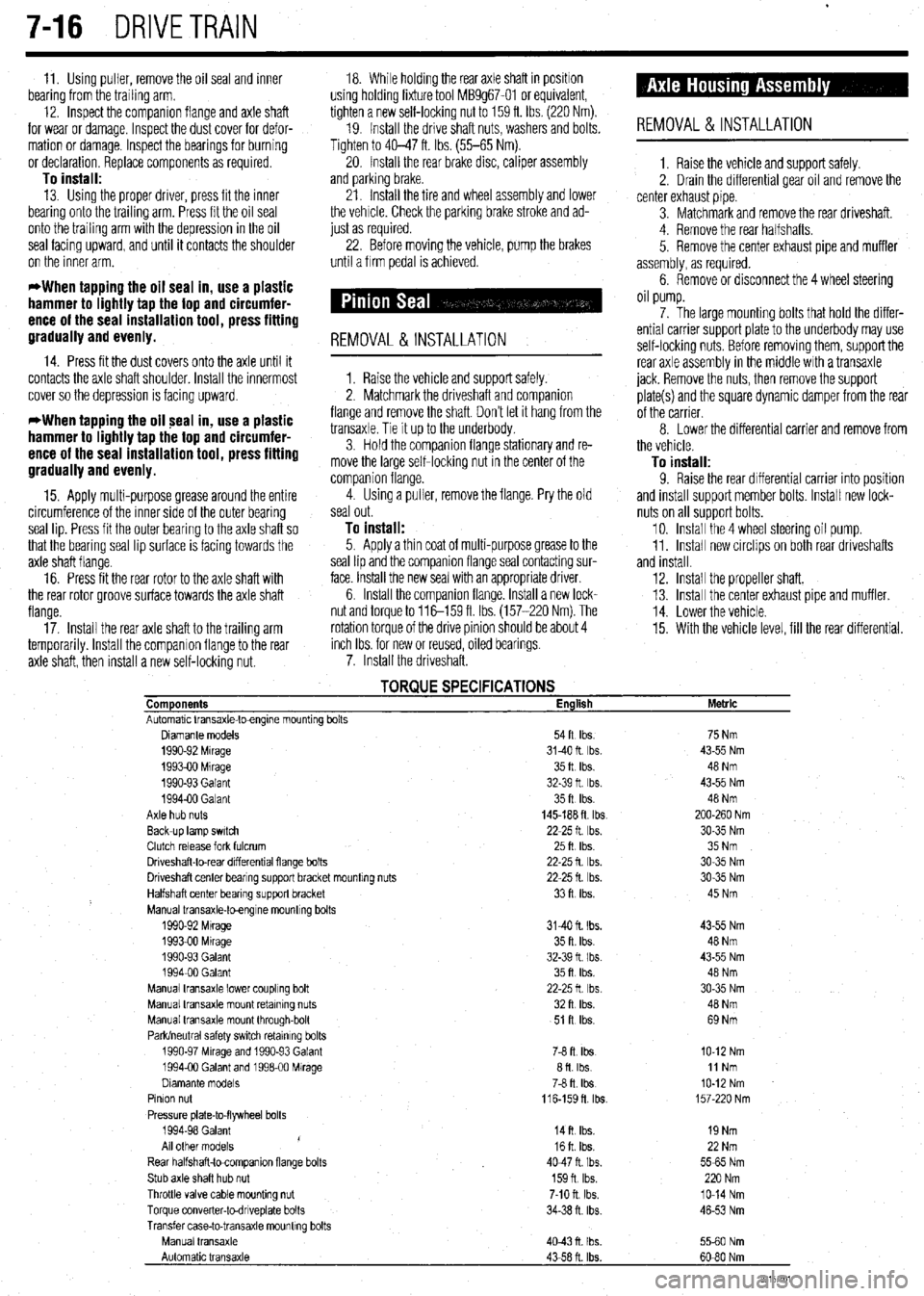
7-16 DRIVETRAIN
11. Using puller, remove the oil seal and inner 18. While holding the rear axle shaft in positron
bearing from the trailing arm. using holding fixture tool MB9g67-01 or equivalent,
12. Inspect the companion flange and axle shaft tighten a new self-locking nut to 159 ft. Ibs. (220 Nm).
for wear or damage. Inspect the dust cover for defor- 19. Install the drive shaft nuts, washers and bolts.
mation or damage. Inspect the bearings for burning Tighten to 40-47 ft. Ibs. (55-65 Nm).
or declaration. Replace components as required 20. Install the rear brake disc, caliper assembly
To install: and parking brake.
13. Using the proper driver, press fit the inner
bearing onto the trailing arm. Press fit the oil seal
onto the trailing arm with the depression in the oil
seal facing upward, and until it contacts the shoulder
on the inner arm. 21. Install the tire and wheel assembly and lower
the vehrcle. Check the parking brake stroke and ad-
just as required.
22. Before moving the vehicle, pump the brakes
until a firm pedal is achieved.
*When tapping the oil seal in, use a plastic
hammer to lightly tap the top and circumfer-
ence of the seal installation tool, press fitting
gradually and evenly.
14. Press fit the dust covers onto the axle until it
contacts the axle shaft shoulder. Install the innermost
cover so the deDression is facino
UDWard.
REMOVAL &INSTALLATION
1. Raise the vehicle and support safely.
2. Matchmark the driveshaft and comoanion . ,
*When tapping the oil seal in, use a plastic
hammer to lightly tap the top and circumfer-
ence of the seal installation tool, press fitting
gradually and evenly. flange and remove the shaft. Don’t let it hang from the
transaxle. Tie It up to the underbody.
3. Hold the companion flange stationary and re-
move the large self-locking nut in the center of the
comoanion flanoe.
15. Apply multi-purpose grease around the entire 4: Using a Gller, remove the flange. Pry the old
circumference of the Inner side of the outer bearing seal out.
seal lip. Press fit the outer bearing to the axle shaft so
To install: that the bearrng seal lip surface is facing towards the 5. Apply a thin coat of multi-purpose grease to the
axle shaft flange. seal lip and the companion flange seal contacting sur-
16. Press fit the rear rotor to the axle shaft with face. Install the new seal with an appropriate driver.
the rear rotor groove surface towards the axle shaft 6. Install the companion flange. Install a new lock-
flange. nut and torque to 116-159 fl Ibs. (157-220 Nm). The
17. Install the rear axle shaft to the trailing arm rotation torque of the drive pinion should be about 4
temporarily. Install the companion flange to the rear inch Ibs. for new or reused, oiled bearings
axle shaft, then install a new self-locking nut. 7. Install the driveshaft.
REMOVAL &INSTALLATION
1. Raise the vehicle and support safely.
2. Drain the differential gear oil and remove the
center exhaust pipe.
3. Matchmark and remove the rear driveshaft.
4. Remove the rear halfshafts.
5. Remove the center exhaust pipe and muffler
assembly, as required.
6. Remove or disconnect the 4 wheel steering
oil pump.
7. The large mounting bolts that hold the differ-
ential carrier support plate to the underbody may use
self-locking nuts. Before removing them, support the
rear axle assembly in the middle with a transaxle
jack. Remove the nuts, then remove the support
plate(s) and the square dynamic damper from the rear
of the carrier.
8 Lower the differential carrier and remove from
the vehicle.
To install: 9. Raise the rear differential carrier into position
and install support member bolts. Install new lock-
nuts on all support bolts.
10. Install the 4 wheel steering oil pump.
11. Install new circlips on both rear driveshafts
and install.
12. Install the propeller shaft.
13. Install the center exhaust pipe and muffler.
14. Lower the vehicle.
15. With the vehicle level, fill the rear differential.
TORQUE SPECIFICATIONS Components English
Automatic Vansaxle-toengme mountrng bolts
Diamante models 54ft Ibs.
1990-92 Mrrage 3140ft Ibs.
199390 Mrrage 35ft Ibs.
1990-93 Galant 32-39 ft Ibs.
199400 Galant 35ft Ibs.
Axle hub nuts 145-188 ft tbs
Back-up lamp swatch 22-25 ft Ibs.
Clutch release fork fulcrum 25ft Ibs
Driveshaft-to-rear drfferentral flange bolts 22-25 fl lb?..
Driveshaft center bearrng support bracket mountrng nuts 22-25 fl. Ibs.
Halfshaft center bearing support bracket 33ft Ibs.
Manual transaxle-toengrne mountrng bolts
1990-92 Mtrage 3140 ft. Ibs.
1993-00 Mrrage 35 ft. Ibs.
1990-93 Galant 32-39 fl I bs.
199400 Galant 35ft Ibs.
Manual transaxle lower coupling bolt 22-25ft Ibs
Manual transaxle mount retaining nuts 32ft Ibs.
Manual transaxle mount through-bolt 51 R Ibs.
Park/neutral safety swatch retainrng bolts
1990-97 Mrrage and 1990-93 Galant 76 ft. Ibs
1994-00 Galant and 199600 Mirage afl Ibs
Dramante models
78 fl. Ibs
Pinion nut
116-159fl lb?..
Pressure plate-to-flywheel bolts
1994-98 Galant
14ft Ibs.
/
All other models 16ft Ibs.
Rear halfshaft-tocompanron flange bolts 4047ft Ibs.
Stub axle shaft hub nut 159n Ibs.
Throttle valve cable mounting nut 7-10 ft. Ibs.
Torque converter-todnveplate bolts 34-38 n. ibs
Transfer case-to-transaxle mounttng bolts
Manual transaxle
4043n Ibs.
Automatic transaxle
43-58 ft. Ibs. Metric
75 Nm
43-55 Nm
48 Nm
43-55 Nm
48 Nm
200-260 Nm
30-35 Nm
35 Nm
30-35 Nm
30-35 Nm
45 Nm
43-55 Nm
48 Nm
43-55 Nm
48 Nm
30-35 Nm
40 Nm
69 Nm
IO-12 Nm
11 Nm
IO-12 Nm
157-220 Nm
19 Nm
22 Nm
5565 Nm
220 Nm
lo-14 Nm
46-53 Nm
5560 Nm
60-80 Nm
93157co1
Page 297 of 408
.
8-2 SUSPENSION AND STEERING
b
REMOVAL &INSTALLATION
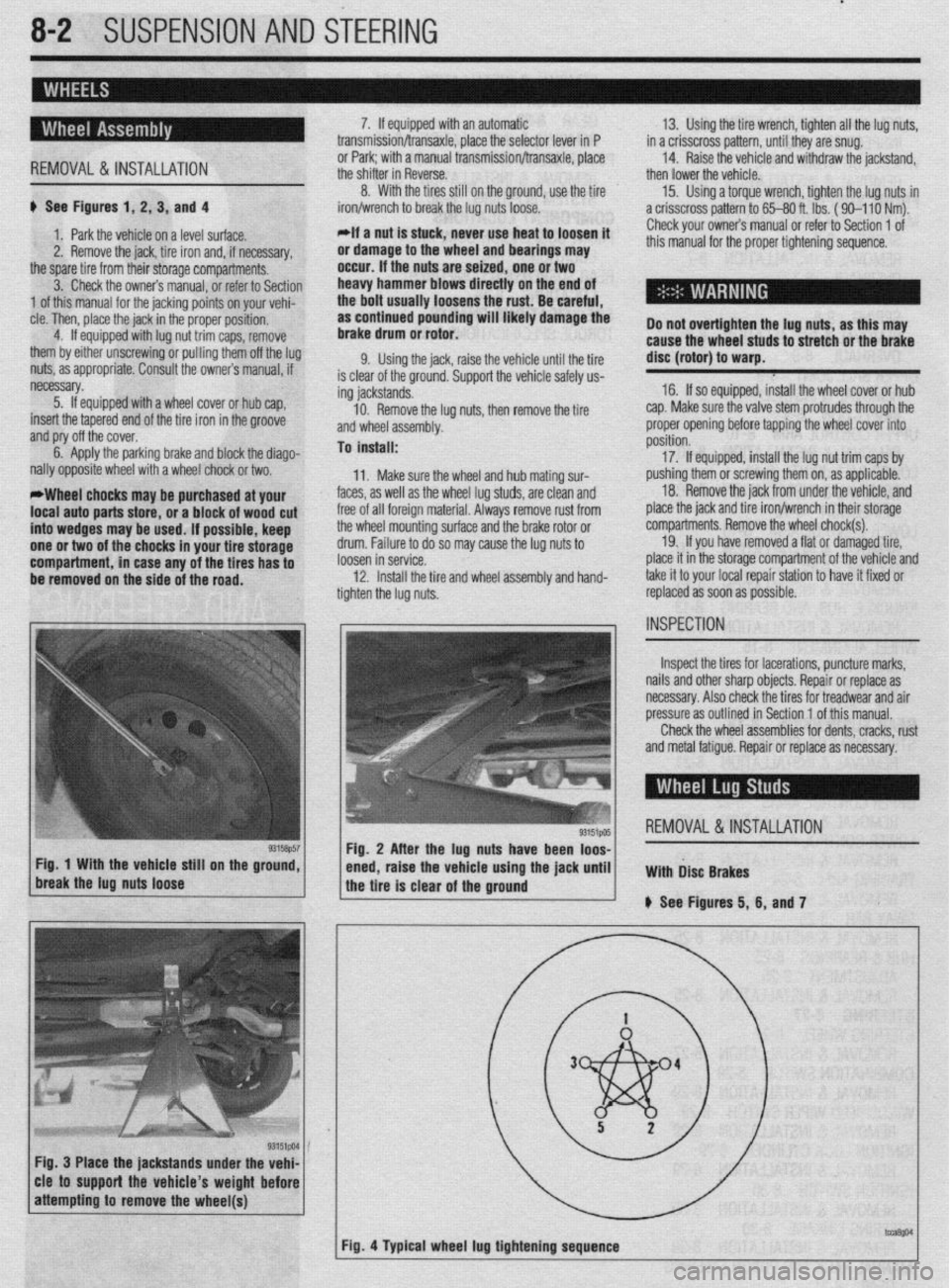
# See Figures 1, 2, 3, and 4
1. Park the vehicle on a level surface.
2. Remove the jack, tire iron and, if necessary,
the spare tire from their storage compartments.
3. Check the owners manual, or refer to Section
1 of this manual for the jacking points on your vehi-
cle. Then, place the jack in the proper position,
4. If equipped with lug nut trim caps, remove
them by either unscrewing or pulling them off the lug
nuts, as appropriate. Consult the owners manual, if
necessary.
5. If equipped with a wheel cover or hub cap,
insert the tapered end of the tire iron in the groove
and pry off the cover.
6. Apply the parking brake and block the diago-
nally opposite wheel with a wheel chock or two.
*Wheel chocks may be purchased at your
local auto parts store, or a block of wood cut
into wedges may be used. If possible, keep
one or two of the chocks in your tire storage
compartment, in case any of the tires has to
be removed on the side of the road. 7. If equipped with an automatic
transmission/transaxle, place the selector lever in P
or Park; with a manual transmission/transaxle, place
the shifter in Reverse.
8. With the tires still on the ground, use the tire
iron/wrench to break the lug nuts loose.
*If a nut is stuck, never use heat to loosen it
or damage to the wheel and bearings may
occur. If the nuts are seized, one or two
heavy hammer blows directly on the end of
the bolt usually loosens the rust. Be careful,
as continued pounding will likely damage the
brake drum or rotor.
9. Using the jack, raise the vehicle until the tire
is clear of the ground. Support the vehicle safely us-
ing jackstands.
10. Remove the lug nuts, then remove the tire
and wheel assembly.
To install:
11. Make sure the wheel and hub mating sur-
faces, as well as the wheel lug studs, are clean and
free of all foreign material. Always remove rust from
the wheel mounting surface and the brake rotor or
drum. Failure to do so may cause the lug nuts to
loosen in service.
12. Install the tire and wheel assembly and hand-
tighten the lug nuts. 13. Using the tire wrench, tighten all the lug nuts,
in a crisscross pattern, until they are snug.
14. Raise the vehicle and withdraw the jackstand,
then lower the vehicle.
15. Using a torque wrench, tighten the lug nuts in
a crisscross pattern to 65-80 ft. lbs. ( 90-l 10 Nm).
Check your owners manual or refer to Section 1 of
this manual for the proper tightening sequence.
Do not overtighten the lug nuts, as this may
cause the wheel studs to stretch or the brake
disc (rotor) to warp.
16. If so equipped, install the wheel cover or hub
cap. Make sure the valve stem protrudes through the
proper opening before tapping the wheel cover into
position.
17. If equipped, install the lug nut trim caps by
pushing them or screwing them on, as applicable.
18. Remove the jack from under the vehicle, and
place the jack and tire iron/wrench in their storage
compartments. Remove the wheel chock(s).
19. If you have removed a flat or damaged tire,
place it in the storage compartment of the vehicle and
take it to your local repair station to have it fixed or
replaced as soon as possible.
Inspect the tires for lacerations, puncture marks,
nails and other sharp objects. Repair or replace as
necessary. Also check the tires for treadwear and air
pressure as outlined in Section 1 of this manual.
Check the wheel assemblies for dents, cracks, rust
and metal fatigue. Repair or replace as necessary.
REMOVAL&INSTALLATION
Fig. 3 Place the jackstands under the vehi-
cle to support the vehicle’s weight before
Page 305 of 408
‘. . ^ .s ”
840 SUSPENSION ANY ik%iiiG
6. Remove thethrough-bolts that attach the up-
per arm to the shafts , . , ,
Except 199
REMOVAL&INSTALLATION
M-98 Galant
These vehicles use a strut type front suspension,
No uooer control arm is used.
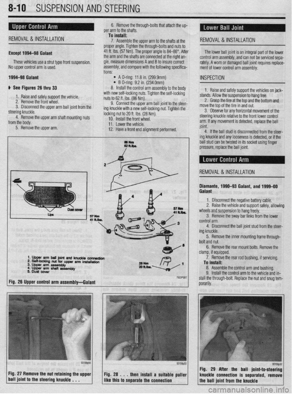
1994-98 Galant
# See Figures 26 thru 33 tions: -
l A O-ring: 11.8 in. (299.9mm) l B O-ring: 9.2 in. (234.0mm)
8. Install the control arm ass
To install:
7. Assemble the upper arm to the shafts at the
proper angle. Tighten the through-bolts and nuts to
41 ft. Ibs. (57 Nm). The proper angle is 84-86”. After
the arm and the shafts are connected at the right an-
gle, measure dimensions A and B to insure correct
assembly, and comoare with the following specifica- REMOVAL& INSTALLATION
The lower ball joint is an integral part of the lower
control arm assembly, and can not be serviced sepa-
rately. A worn or damaged ball joint requires replace-
ment of lower control arm assembly.
embly to the body
_ IL_ --at I-., ..-
INSPECTION
1. Raise and safely support the vehicles on jack-
with new self-locking nuts. Tighten one sea-rockrng
nuts to 62 ft. Ibs. (86 Nm).
9. Connect the upper arm ball joint to the steer-
ing knuckle with a new self-locking nut. Tighten the
locking ^_ ~. I- -
10.
11 . L”WCl LI It: “Cl Illx.
12. Have
a front end alinnmen
nut to 20 ft. Ibs. (28 Nm). ve for any horizontal movement of the
Install the front wheel. steering knuckle relative to the front lower control
I ml.,,.* ,I.+. .,^l.:^l^ arm. If any movement is detected, replace the ball
t performed. joint.
---g -
4. If the ball stud is disconnected from the steer-
ing knuckle and any looseness is detected, or if the
~~ k hall dir! ran ho twiatm-l in itr cnrlmt II&WI finnnr ““.I VLVV “Yll YY L..l”L”” #II IIU UY”I\“L u.l,,,y ““y”’
/ pressure, replace the ball joint, stands. Allow the suspension to hang free.
2. Grasp the tire at the top and the bottom and
move the tar
3. Obser 1. Raise and safely support the vehicle.
2. Remove the front wheel.
3. Disconnect the upper arm ball joint from the
steering knuckle.
4. Remove the upper arm shaft mounting nuts
from the body.
5. Remove the upper arm.
d REMOVAL &INSTALLATION
rck ,-.-.
Diamante, 1990-93 Galant, and 1994-00
3. Remove the sway bar links from the lower
..^^l-^l ^--
titJIILIlJI alIll. 4. Disconnect the bail joint stud from the steer-
ing knuckle.
5. Remove the inner mounting frame through-
bolt and nut.
6. Remove the rear mount bolts. Remove the
clamp, if equipped.
‘YUN
- ,-. R \_ 1 2m.lk~ -
7923Fw7
7. Remove the rear rod bushing, if servicing.
To install:
8. Assemble the control arm and bushing.
9. Install the control arm to the vehicle and in-
stall the through-bolt. Replace the,nut and snua tem-
porarily. - 1 Fig. 26 Upper control arm assembly-Galant
Fig. 27 Remove the nut retaining the upper
1 ball joint to the steering knuckle , . . Fig. 29 A
Fig. 28 . , . then install a suitable puller
I I knuckle COI
like this to separate the connection Galant
1, Disconnect the negative battery cable.
2. Raise the vehicle and support safely, allowing
wheels and suspension to hang freely.
Page 338 of 408
9-2 BRAKES
Hydraulic systems are used to actuate the brakes
of all modern automobiles. The system transports the
power required to force the frictional surfaces of the
braking system together from the pedal to the indi-
vidual brake units at each wheel. A hydraulic system
is used for two reasons.
First, fluid under pressure can be carried to all
parts of an automobile by small pipes and flexible
hoses without taking up a significant amount of room
or posing routing problems.
Second, a great mechanical advantage can be
given to the brake pedal end of the system, and the
foot pressure required to actuate the brakes can be
reduced by making the surface area of the master
cylinder pistons smaller than that of any of the pis-
tons in the wheel cylinders or calipers.
The master cylinder consists of a fluid reservoir
along with a double cylinder and piston assembly.
Double type master cylinders are designed to sepa-
rate the front and rear braking systems hydraulically
in case of a leak. The master cylinder converts me-
chanical motion from the pedal into hydraulic pres-
sure within the lines. This pressure is translated back
into mechanical motion at the wheels by either the
wheel cylinder (drum brakes) or the caliper (disc
brakes).
Steel lines carry the brake fluid to a point on the
vehicle’s frame near each of the vehicle’s wheels. The
fluid is then carried to the calipers and wheel cylin-
ders by flexible tubes in order to allow for suspen-
sion and steering movements.
In drum brake systems, each wheel cylinder con-
tains two pistons, one at either end, which push out-
ward in opposite directions and force the brake shoe
into contact with the drum.
In disc brake systems, the cylinders are part of the
calipers. At least one cylinder in each caliper is used
to force the brake pads against the disc.
All pistons employ some type of seal, usually
made of rubber, to minimize fluid leakage. A rubber
dust boot seals the outer end of the cylinder against
dust and dirt. The boot fits around the outer end of
the piston on disc brake calipers, and around the
brake actuating rod on wheel cylinders.
The hydraulic system operates as follows: When at
rest, the entire system, from the piston(s) in the mas-
ter cylinder to those in the wheel cylinders or
calipers, is full of brake fluid. Upon application of the
brake pedal, fluid trapped in front of the master cylin-
der piston(s) is forced through the lines to the wheel
cylinders. Here, it forces the pistons outward, in the
case of drum brakes, and inward toward the disc, in
the case of disc brakes. The motion of the pistons is
opposed by return springs mounted outside the
cylinders in drum brakes, and by spring seals, in disc
brakes.
Upon release of the brake pedal, a spring located
inside the master cylinder immediately returns the
master cylinder pistons to the normal position. The
pistons contain check valves and the master cylinder
I
has compensating ports drilled in it. These are un-
covered as the pistons reach their normal position.
The piston check valves allow fluid to flow toward the
wheel cylinders or calipers as the pistons withdraw.
Then, as the return springs force the brake pads or
shoes into the released position, the excess fluid
reservoir through the compensating ports. It is during the time the pedal is in the released position that any
fluid that has leaked out of the system will be re-
placed through the compensating ports.
Dual circuit master cylinders employ two pistons,
located one behind the other, in the same cylinder.
The primary piston is actuated directly by mechanical
linkage from the brake pedal through the power
booster. The secondary piston is actuated by fluid
trapped between the two pistons. If a leak develops in
front of the secondary piston, it moves forward until it
bottoms against the front of the master cylinder, and
the fluid trapped between the pistons will operate the
rear brakes. If the rear brakes develop a leak, the pri-
mary piston will move forward until direct contact
with the secondary piston takes place, and it will
force the secondary piston to actuate the front brakes.
In either case, the brake pedal moves farther when the
brakes are applied, and less braking power is avail-
able.
All dual circuit systems use a switch to warn the
driver when only half of the brake system is opera-
tional. This switch is usually located in a valve body
which is mounted on the firewall or the frame below
the master cylinder. A hydraulic piston receives pres-
sure from both circuits, each circuits pressure being
applied to one end of the piston. When the pressures
are in balance, the piston remains stationary. When
one circuit has a leak, however, the greater pressure
in that circuit during application of the brakes will
push the piston to one side, closing the switch and
activating the brake warning light.
In disc brake systems, this valve body also con-
tains a metering valve and, in some cases, a propor-
tioning valve. The metering valve keeps pressure
from traveling to the disc brakes on the front wheels
until the brake shoes on the rear wheels have con-
tacted the drums, ensuring that the front brakes will
never be used alone. The proportioning valve con-
trols the pressure to the rear brakes to lessen the
chance of rear wheel lock-up during very hard brak-
ing.
Warning lights may be tested by depressing the
brake pedal and holding it while opening one of the
wheel cylinder bleeder screws. If this does not cause
the light to go on, substitute a new lamp, make conti-
nuity checks, and, finally, replace the switch as nec-
essary.
The hydraulic system may
be checked for leaks by applying pressure to the pedal gradually and steadily.
If the pedal sinks very slowly to the floor, the system
has a leak. This is not to be confused with a springy
or spongy feel due to the compression of air within
the lines. If the system leaks, there will be a gradual
change in the position of the pedal with a constant
pressure.
Check for leaks along all lines and at wheel cylin-
ders. If no external leaks are apparent, the problem is
inside the master cylinder,
DISC BRAKES
Instead of the traditional expanding brakes that
press outward against a circular drum, disc brake
systems utilize a disc (rotor) with brake pads posi-
tioned on either side of it. An easily-seen analogy is
the hand brake arrangement on a bicycle. The pads
squeeze onto the rim of the bike wheel, slowing its
motion. Automobile disc brakes use the identical principle but apply the braking effort to a separate
disc instead of the wheel.
The disc (rotor) is a casting, usually equipped with
cooling fins between the two braking surfaces. This
enables air to circulate between the braking surfaces
making them less sensitive to heat buildup and more
resistant to fade. Dirt and water do not drastically af-
fect braking action since contaminants are thrown off
by the centrifugal action of the rotor or scraped off
the by the pads. Also, the equal clamping action of
the two brake pads tends to ensure uniform, straight
line stops. Disc brakes are inherently self-adjusting.
There are three general types of disc brake:
1. A fixed caliper.
2. A floating caliper.
3. A sliding caliper.
The fixed caliper design uses two pistons
mounted on either side of the rotor (in each side of
the caliper). The caliper is mounted rigidly and does
not move.
The sliding and floating designs are quite similar.
In fact, these two types are often lumped together. In
both designs, the pad on the inside of the rotor is
moved into contact with the rotor by hydraulic force.
The caliper, which is not held in a fixed position,
moves slightly, bringing the outside pad into contact
with the rotor. There are various methods of attaching
floating calipers. Some pivot at the bottom or top,
and some slide on mounting bolts. In any event, the
end result is the same.
DRUM BRAKES
Drum brakes employ two brake shoes mounted on
a stationary backing plate. These shoes are posi-
tioned inside a circular drum which rotates with the
wheel assembly. The shoes are held in place by
springs. This allows them to slide toward the drums
(when they are applied) while keeping the linings and
drums in alignment. The shoes are actuated by a
wheel cylinder which is mounted at the top of the
backing plate. When the brakes are applied, hydraulic
pressure forces the wheel cylinder’s actuating links
outward. Since these links bear directly against the
top of the brake shoes, the tops of the shoes are then
forced against the inner side of the drum. This action
forces the bottoms of the two shoes to contact the
brake drum by rotating the entire assembly slightly
(known as servo action). When pressure within the
wheel cylinder is relaxed, return springs pull the
shoes back away from the drum.
Most modern drum brakes are designed to self-
adjust themselves during application when the vehi-
cle is moving in reverse. This motion causes both
shoes to rotate very slightly with the drum, rocking
an adjusting lever, thereby causing rotation of the ad-
justing screw. Some drum brake systems are de-
signed to self-adjust during application whenever the
brakes are applied. This on-board adjustment system
reduces the need for maintenance adjustments and
keeps both the brake function and pedal feel satisfac-
tory.
POWER BOOSTERS
Virtually all modern vehicles use a vacuum as-
sisted power brake system to multiply the braking
force and reduce pedal effort. Since vacuum is always
available when the engine is operating, the system is
Page 339 of 408
BRAKiS 9-3
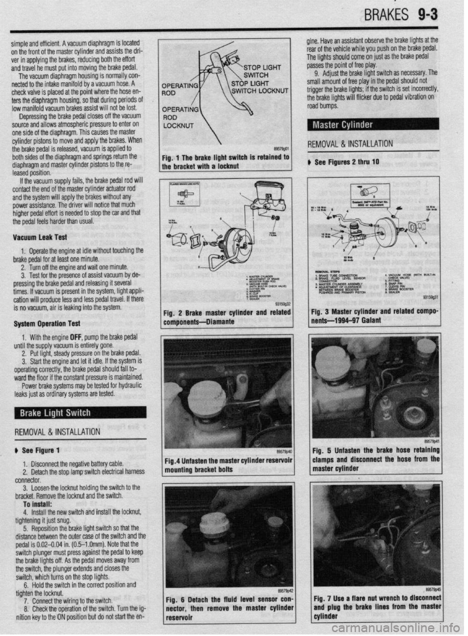
simple and efficient. A vacuum diaphragm is located gine. Have an assistant observe the brake lights at the
on the front of the master cylinder and assists the dri- rear of the vehicle while you push on the brake pedal.
ver in applying the brakes, reducing both the effort The lights should come on just as the brake pedal
and travel he must put into moving the brake pedal. passes the point of free play.
The vacuum diaphragm housing is normally con- 9.
Adjust the brake light switch as necessary. The
netted to the intake manifold by a vacuum hose. A small amount of free play in the
pedal should not
check valve is placed at the point where the hose en-
ters the diaphragm housing, so that during periods
Of low manifold vacuum brakes assist will not be lost.
Depressing the brake pedal closes off the vacuum
source and allows atmospheric pressure to enter on
one side of the diaphragm. This causes the master
cylinder pistons to move and apply the brakes. When
the brake pedal is released, vacuum is applied to
REMOVAL &INSTALLATION
both sides of the diaphragm and springs return the
diaphragm and master cylinder pistons to the re- ) See Figures 2 thru 10
leased position.
If the vacuum supply fails, the brake pedal rod will
contact the end of the master cylinder actuator rod
and the system will apply the brakes without any
power assistance. The driver will notice that much
higher pedal effort is needed to stop the car and that
the pedal feels harder than usual.
Vacuum leak Test
1. Operate the engine at idle without touching the
brake pedal for at least one minute.
2. Turn off the engine and wait one minute.
3. Test for the presence of assist vacuum by de-
pressing the brake pedal and releasing it several
3 MASTER N- 188A11Ly
times. If vacuum is present in the system, light appli- . KLNsIMEm 0s CLWRANCE
BETWEEN BRAKE WOSTER
cation will produce less and less pedal travel. If there PUSHROO AN0 PRIMARY PISTCU
is no vacuum, air is leaking into the system.
System Operation Test
1. With the engine OFF, pump the brake pedal
until the supply vacuum is entirely gone.
2. Put light, steady pressure on the brake pedal.
3. Start the engine and let it idle. If the system is
operating correctly, the brake pedal should fall to-
ward the floor if the constant pressure is maintained.
Power brake systems may be tested for hydraulic
leaks just as ordinary systems are tested.
REMOVAL&INSTALLATION
$ See Figure 1
1. Disconnect the negative battery cable.
2. Detach the stop lamp switch electrical harness
connector.
3. Loosenthe locknut holding the switch to the
bracket. Remove the locknut and the switch.
To install:
4.
Install the new switch and install the locknut,
tightening it just snug.
5. Reposition the brake light switch so that the
distance between the outer case of the switch and the
pedal is 0.02-0.04 in. (0.5-l .Omm). Note that the
switch plunger must press against the pedal to keep
the brake lights off. As the pedal moves away from
the switch, the plunger extends and closes the
switch, which turns on the stop lights.
6.
Hold the switch in the correct position and
tighten the locknut.
7. Connect the wiring to the switch.
8. Check the operation of the switch. Turn the ig-
nition key to the ON position but do not start the en-
Page 342 of 408
.
9-6 BRAKES
REMOVAL & INSTALLATION
I) See Figure 2
1. Disconnect the negative battery cable.
2. Locate the proportioning valve, usually below
the master cylinder.
3. Tag and disconnect the brake lines from the
valve.
Brake fluid contains poiygiycoi ethers and
poiygiycois. Avoid contact with the eyes and
wash your hands thoroughly after handling
brake fluid. if you do get brake fluid in your
eyes, flush your eyes with clean, running wa-
ter for 15 minutes. if eye irritation persists,
or if you have taken brake fluid internally,
IMMEDIATELY seek medical assistance.
4. Remove the proportioning valve from the en-
gine compartment.
To install:
5. The installation is the reverse of the removal
procedure. Bleed the brakes in the following order:
6. Diamante
a. Right rear caliper
b. Left front caliper
c. Left rear caliper
d. Right front caliper
7. Mirage and Gaiant
a. Left rear wheel cylinder or caliper
b. Right front cylinder
c. Right rear wheel cylinder or caliper
d. Left front caliper
8. Connect the negative battery cable and check
the brakes for proper operation.
Clean, high quality brake fluid is essential to
the safe and proper operation of the brake
system. You should always buy the highest
quality brake fluid that is available. if the
brake fluid becomes contaminated, drain and
flush the system, then refill the master cyiin-
der with new fluid. Never reuse any brake
fluid. Any brake fluid that is removed from
the system should be discarded. Also, do not
allow any brake fluid to come in contact with
a painted surface; it will damage the paint.
Metal lines and rubber brake hoses should be
checked frequently for leaks and external damage.
Metal lines are particularly prone to crushing and
kinking under the vehicle. Any such deformation can
restrict the proper flow of fluid and therefore impair
braking at the wheels. Rubber hoses should be
checked for cracking or scraping; such damage can
create a weak spot in the hose and it could fail under
pressure.
Any time the lines are removed or disconnected,
extreme cleanliness must be observed. Clean all
joints and connections before disassembly (use a stiff bristle brush and clean brake fluid); be sure to
plug the lines and ports as soon as they are opened.
New lines and hoses should be flushed clean with
brake fluid before installation to remove any contami-
nation. REMOVAL&INSTALLATION
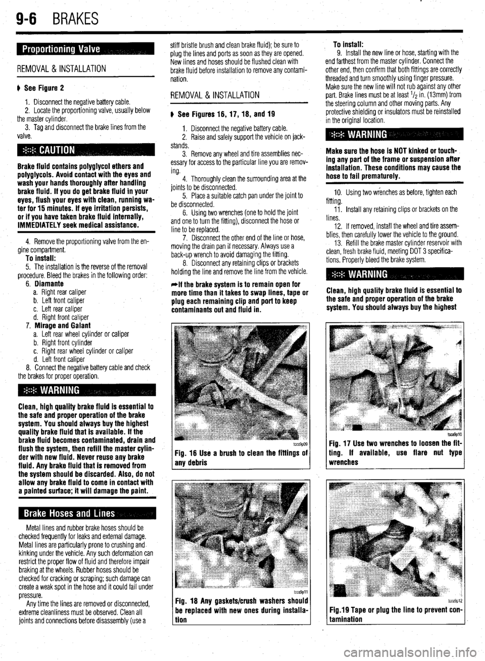
) See Figures 16, 17, 18, and 19
1. Disconnect the negative battery cable.
2. Raise and safely support the vehicle on jack-
stands.
3. Remove any wheel and tire assemblies nec-
essary for access to the particular line you are remov-
ing.
4. Thoroughly clean the surrounding area at the
joints to be disconnected.
5. Place a suitable catch pan under the joint to
be disconnected.
6. Using two wrenches (one to hold the joint
and one to turn the fitting), disconnect the hose or
line to be replaced.
7. Disconnect the other end of the line or hose,
moving the drain pan if necessary. Always use a
back-up wrench to avoid damaging the fitting.
8. Disconnect any retaining clips or brackets
holding the line and remove the line from the vehicle.
-if the brake system is to remain open for
more time than it takes to swap lines, tape or
plug each remaining clip and port to keep
contaminants out and fluid in.
I tcca9p09 tcca9p09 Fig. 16 Use a brush to clean the fittings of Fig. 16 Use a brush to clean the fittings of
any debris any debris
tcca9pll Fig. 18 Any gaskets/crush washers should
be replaced with new ones during instaiia-
tion To install:
9. Install the new line or hose, starting with the
end farthest from the master cylinder. Connect the
other end, then confirm that both fittings are correctly
threaded and turn smoothly using finger pressure.
Make sure the new line will not rub against any other
part. Brake lines must be at least l/z in. (13mm) from
the steering column and other moving parts. Any
protective shielding or insulators must be reinstalled
in the original location.
Make sure the hose is NOT kinked or touch-
ing any part of the frame or suspension after
installation. These conditions may cause the
hose to fail prematurely.
10. Using two wrenches as before, tighten each
fitting.
Ii. Install any retaining clips or brackets on the
lines.
12. If removed, install the wheel and tire assem-
blies, then carefully lower the vehicle to the ground.
13. Refill the brake master cylinder reservoir with
clean, fresh brake fluid, meeting DOT 3 specifica-
tions. Properly bleed the brake system.
Clean, high quality brake fluid is essential to
the safe and proper operation of the brake
system. You should always buy the highest
tcca9p10 Fig. 17 Use two wrenches to loosen the fit-
ting. If available, use flare nut type
wrenches
tcca9p12 Fig.19 Tape or plug the line to prevent con-
tamination
Page 360 of 408
9-24 BRAKES
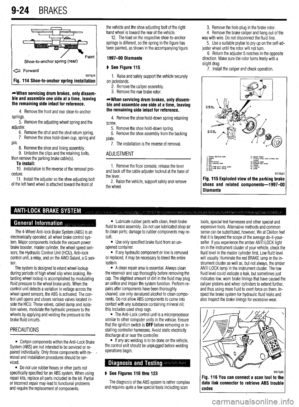
Shoe-to-anchor spring (rear)
e Forward
69579946 Fig. 114 Shoe-to-anchor spring installation
*When servicing drum
brakes, only dissem-
ble and assemble one side at a time, leaving
the remaining side intact for reference.
4. Remove the front and rear shoe-to-anchor
springs.
5. Remove the adjusting wheel spring and the
adjuster.
6. Remove the strut and the strut return spring.
7. Remove the shoe hold-down cup, spring and
pin.
8. Remove the shoe and lining assembly.
9. Unfasten the clips and the retaining bolts,
then remove the parking brake cable(s).
To install: 10. Installation is the reverse of the removal pro-
cedure.
11. Install the adjuster so the shoe adjusting bolt
of the left hand wheel is attached toward the front of the vehicle and the shoe adjusting bolt of the right
hand wheel is toward the rear of the vehicle. -
12. The load on the respective shoe-to-anchor
springs is different, so the spring in the figure has
hen painteb, a> shm in the a~~0mparrying figure.
1997-00 Diamante
‘) See Figure 115
1. Raise and safely support the vehicle securely
on jackstands.
2. Remove the caliper assembly.
3. Remove the rear brake rotor.
*When servicing drum brakes, only dissem-
ble and assemble one side at a time, leaving
the remaining side intact for reference.
4. Remove the shoe hold-down spring retaining
screw.
5. Remove the shoe hold-down spring.
6. Remove the shoe assembly from the backing
plate.
7. The installation is the reverse of removal.
ADJUSTMENT
1. Remove the floor console, release the lever
and back off the cable adjuster locknut at the base of
the lever.
2. Raise the vehicle, support safely and remove
the wheel. 3. Remove the hole plug in the brake rotor.
4. Remove the brake caliper and hang out of the
way with wire. Do not disconnect the fluid line.
5. Use a suitable prybar to pry up on the self-ad-
juskr V&I&I unti tie T&IT wi\ not tirn.
6. Return the adjuster 5 notches in the opposite
direction. Make sure the rotor turns freely with a
slight drag.
7. Install the caliper and check operation.
9. Shoe 93159go3 Fig. 115 Exploded view of the parking brake
shoes and related components-l 997-00
Diamante
The 4-Wheel Anti-lock Brake System (ABS) is an
electronically operated, all wheel brake control sys-
tem. Major components include the vacuum power
brake booster, master cylinder, the wheel speed sen-
sors, the Hydraulic Control Unit (HCU), Anti-lock
control unit, a relay, and on the AWD Galant, a G sen-
sor.
The system is designed to retard wheel lockup
during periods of high wheel slip when braking. Re-
tarding wheel lockup is accomplished by modulating
fluid pressure to the wheel brake units. When the
control unit detects a variation in voltage across the
wheel speed sensors, the ABS is activated. The con-
trol unit opens and closes various valves located in-
side the HCU. These valves, called dump and isola-
tion valves, modulate the hydraulic pressure to the
wheels by applying and venting the pressure to the
brake fluid circuits.
PRECAUTIONS
l Certain components within the Anti-Lock Brake
System (ABS) are not intended to be serviced or re-
paired individually. Only those components with re- !
moval and installation procedures should be ser-
viced.
0 Do not use rubber hoses or other parts not
specifically specified for an ABS system. When using
repair kits, replace all parts included in the kit. Partial
or incorrect repair may lead to functional problems
and require the replacement of components.
l Lubricate rubber parts with clean, fresh brake
fluid to ease assembly. Do not use lubricated shop air
to clean parts; damage to rubber components may re-
sult.
l Use only specified brake fluid from an un-
opened container.
l If any hydraulic component or line is removed
or replaced, it may be necessary to bleed the entire
system.
l A clean repair area is essential. Always clean
the reservoir and cap thoroughly before removing the
cap. The slightest amount of dirt in the fluid may plug
an orifice and impair the system function. Perform re-
pairs after components have been thoroughly
cleaned; use only denatured alcohol to clean compo-
nents. Do not allow ABS components to come into
contact with any substance containing mineral oil;
this includes used shop rags.
l The Anti-Lock control unit is a microprocessor
similar to other computer units in the vehicle. Ensure
that the ignition switch is
OFF before removing or in-
stalling controller harnesses. Avoid static electricity
discharge at or near the controller.
l If any arc welding is to be done on the vehicle,
the control unit should be unplugged before welding
operations begin.
) See Figures 116 thru 123
The diagnosis of the ABS system is rather complex
and requires quite a few special tools including scan tools, special test harnesses and other special and
expensive tools. Alternative methods and common
sense can be substituted, however, We at Chilton feel
that it is beyond the scope of the average do-it-your-
selfer. If you experience the amber ANTI LOCK light
on in the instrument cluster of your vehicle, check the
fluid level in the master cylinder first. Low fluid level
will usually illuminate the red BRAKE lamp in the in-
strument cluster as well as, but not always, the amber
ANTI LOCK lamp in the instrument cluster. The low
fluid level could indicate a leak, but sometimes just
indicates low, worn brake linings that have caused the
caliper pistons and wheel cylinders to extend further,
and thus using more fluid to exert force on them. In-
spect the brake system for hydraulic fluid leaks and
also inspect the brake linings for excessive wear.
89579956 Fig. 116 You can connect a scan tool to the
data link connector to retrieve ABS trouble
codes
Page 383 of 408

TROUBLESHOOTING INDEX 11-2
SECTION 1: ENGINE 11-2
SECTION 2: DRIVE TRAIN
11-3
SECTION 3:BRAKESYSTEM 11-3
SECTION 4:WHEELS,TIRES, STEERING,
AND SUSPENSION II-4
SECTION 5: ELECTRICAL
ACCESSORIES II-4
SECTION 6:lNSTRUMENTSAND
GAUGES II-5
SECTION 7:CLlMATE CONTROL II-5
DIAGNOSTIC PROCEDURES II-6
SECTION 1: ENGINE II-6
ENGINE STARTING PROBLEMS II-6
ENGINE RUNNING CONDITIONS II-7
ENGINE NOISES,ODORSAND
VIBRATIONS II-8
ENGINE ELECTRICALSYSTEM 11-8
ENGINE COOLING SYSTEM II-8
ENGINE EXHAUSTSYSTEM II-9
SECTION 2: DRIVE TRAIN
II-9
AUTOMATIC TRANSMISSION II-9
MANUALTRANSMISSION II-10
CLUTCH II-10
DIFFERENTIAL AND FINAL
DRIVE II-10
TRANSFER ASSEMBLY II-10
DRIVESHAFT II-10
AXLES II-II
OTHER DRIVE TRAIN
CONDITIONS II-II
SECTION 3:BRAKE SYSTEM II-II
BRAKESYSTEM
TROUBLESHOOTING II-II
SECTION 4:WHEELS, TIRES, STEERING
AND SUSPENSION II-12
WHEELSAND WHEEL
BEARINGS II-12
TIRES II-12
STEERING II-12
SUSPENSION II-12
DRIVING NOISES AND
VIBRATIONS II-13
SECTION 5:ELECTRlCAL
ACCESSORIES II-13 -
HEADLIGHTS II-13
TAIL, RUNNING AND SIDE MARKER
LIGHTS II-13
INTERIOR LIGHTS II-14
BRAKE LIGHTS II-14
WARNING LIGHTS II-14
TURN SlGNALAND4-WAYHAZARD
LIGHTS II-15
WINDSHIELD WIPERS II-15
SECTION 6:lNSTRUMENTSAND
GAUGUES II-15
I
SPEEDOMETER(CABLE
OPERATED) II-15
SPEEDOMETER(ELECTRONICALLY
OPERATED) II-16
FUEL,TEMPERATUREAkJD OIL
PRESSURE GAUGES II-16 SECTION 7:CLlMATECON
AIR CONDITIONER ll-
HEATER II-16 TR(
-16 IL II-16