Page 148 of 408

,
DRIVEABILITYAND EMISSIONS CONTROLS 4-5
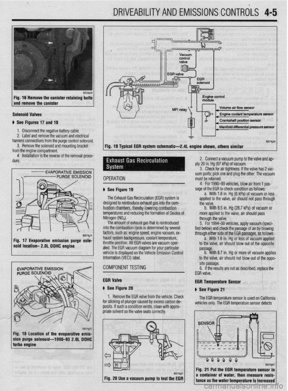
Fig. 16 Remove the canister retaining bolts
and remove the canister
Solenoid Valves
u See Figures 17 and 18
1 b Disconnect the negative battery cable.
2. Label and remove the vacuum and electrical
harness connections from the purge control solenoid.
3. Remove the solenoid and mounting bracket
from the engine compartment.
4. Installation is the reverse of the removal proce-
dure.
I
- EVAPORATIVE EMISSION
Fig. 18 location of the evaporative emis-
purge solenoid-1990-93 2.OL DDHC
Volume air flow seneftr I
I Manifold diierential pressure m
&a$34
Fig. 19 Typical EGR system schematie-2.4L engine shown, others similar
IPERATION uum ports; pick one and plug the other. The vacuum
must be retained.
1 See Figure 19
The Exhaust Gas Recirculation (EM) system is
lesigned to reintroduce exhaust gas into the com-
ttii valve.
rustion chambers, thereby lowering combustion b. With 8.5 in. Hg (28.7 kPa) of vacuum or
emperatures and reducing the formation of Oxides of more applied to the valve, air should pass 4. For 1990-93 vehicles. blow air from 1 oas-
sage of the EGR to check condition as foffows--
a. With 1.8 in. Hg (6 kPa) of vacuum or less
aoolied to the valve. air should not oass throuah
litrogen (NO,).
The amount of exhaust gas that is reintroduced
Ito the combustion cycle is determined by several
actors, such as: engine speed, engine vacuum, ex-
raust system backpressure, coolant temperature,
Irottle position. All EGR valves are vacuum oper-
ted. The EGR vacuum diagram for your particular
chicle is displayed on the Vehicle Emission Control
iformation (VECI) label. through the valve.
5. For 1994-00 vehicles, apply vacuum (speci-
fied below) and check the passage of air by blowing
through either side of the EGR passages, as follows:
a. With 1 .?I in. Hg or less of vacuum applied
to the valve, air should blow out of the opposite
passa e.
b. %ith 8.7 in. Hg or more of vacuum applies
to the valve, air should not blow out of the oppo-
:OMPONENTTESTiNG site passage.
6. If the results are not as described, replace the
EGR valve.
iGR Valve
t See Figure 20
1. Remove the EGR valve from the vehicle. Check
I”..““.
:or sticking of plunger caused by excess carbon de-
losits. If such a condition exists, clean with appro- EGR Temperature Lan*nr
u See Figure 21
The EGR temperature sensor is used on California
vehicles only. The EGR temperature sensor detects
Fig. 20 Use a vacuum pump to test the EGR
I I
a coni tance i of water. then measure resis-
I ms the water temperature is increased
Page 158 of 408

DRIVEABILITYAND EMlSSlONSCONTROiS 4-15
it into a pulse signal. The PCM receiv
es this signal
and then computes the engine speed ad controls the
fuel injector timing and ignition timing based on this
input.
TESTING
This sensor produces a pulse signal based on in-
formation gathered while the engine is running. Test-
ing the CKP sensor requires several special tools that
are very expensive to purchase. Due to this fact, we at
Chilton have determined testing this sensor to be be-
yond the scope of the do-it-yourself mechanic. The
sensor can be monitored with an appropriate scan
tool using a data display or other data stream infor-
mation Follow the instructions included with the
scan tool for information on accessing the data.
REMOVAL<jSTALLATlON
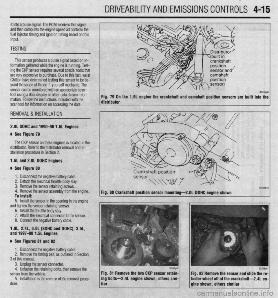
2.OL SDHC and 1990-96 1.5L Engines are built
89574ga3 into the
9 See Figure 79
The CKP sensor on these engines is located in the
distributor. Refer to the distributor removal and in-
stallation procedure in Section 2.
1.6L and 2.OL DDHC Engines
b See Figure 80
1. Disconnect the negative battery cable.
2. Detach the electrical throttle body stay.
3. Remove the sensor retaining screws,
4. Remove the sensor assembly from the engine.
To install:
5. Install the sensor in the openina in the enaine
and tighten the sensor retaining’screvk -
6. Install the throttle body stay,
7. Attach the electrical connector to the sensor.
8. Connect the negative battery cable.
1.8L, 2.4L, 3.OL (SOHC and DOHC), 3.5L,
and 1997-00 1.5L Engines
b See Figures 81 and 82
1. Disconnect the negative battery cable.
2. Remove the timing belt, as outlined in Section
3 of this manual.
3. Unplug the sensor connector.
4. Unfasten the retaining bolts, then remove the
sensor from the vehicle.
5. Installation is the reverse of the removal proce-
dure. ’ Fig. 81 Remove the two CKP sensor retain-
Fig. 82 Remove the sensor and slide the re-
1 / gfne shown, others similar ’ -1 ing bolts-2 4L engine shown others sim-
ilar . ’ luctor wheel off of the crankshaft-2 4L en
Page 362 of 408

Diagnostic InspeclM item
trouble
code no. Detection
conditions
11 Front right wheel speed sensor
12 Front left wheel speed sensor
13 Rear right wheel speed sensor Open circuit
6 c
14
Rear left wheel speed sensor
16
Power supply system
21 Front right wheel speed sensor
22 Front left wheel speed sensor Short circuit 4 0. C
0, c
23
Rear right wheel speed sensof
24 Rear left wheel speed sensor
25 Front right wheel speed sensor
26 Front left wheel speed sensor Excessive gap
B, c
27 / Rear right wheel speed sensor
26 1 Rear left wheel speed sew
33
Stop light switch system
35 Front right wheel speed sensor
36 Front left wheel speed sensor
37 Rear right wheel speed sensor Pulse orocessina
pheei speed in&t
corresponding to a
vehicle speed of 300
46 Rear left solenoid valve (outside)
51
Valve relay
52 Vti relay
53
Motor relay
54
Motor relay ON impossible ,
A B. C
OFF impossrble
A
ON impossible
B
OFF impossible
B, c
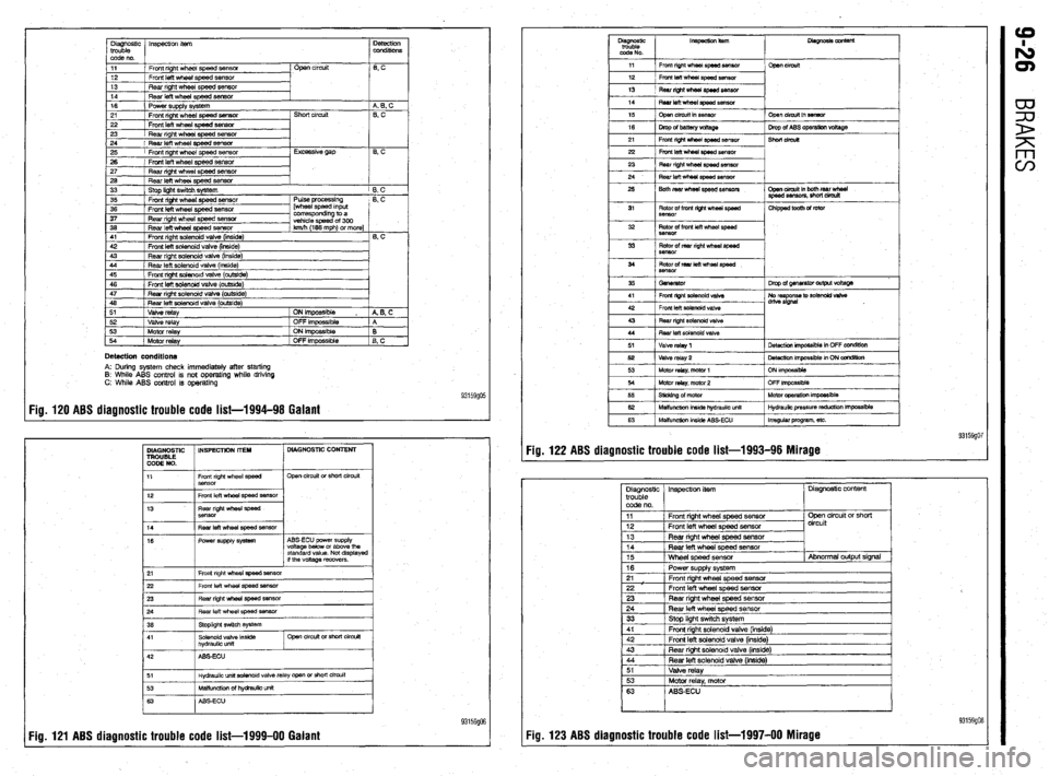
Detection conditions A: During system check immediately after starting
8: While ABS control is not operating while driving
C: While ABS control is operating
Fig. 120 ABS diagnostic trouble code list-1994-98 Galant 93159go5
DIAGNOSTIC INSPECTION IT’EH DIAGNOSTIC CONTENT
TROUBLE
CODE NO.
11 Front right wheel speed
Sensor Open circuit or short circuit
12
13 Front left wheel speed sensor
Rear right wheel speed
SBnsor
14
16 Fear left wheel speed ssnsor
Power supply system ABS-ECU power supply
voltage below or above the
standard value. Not displayed
if the voltage recovers.
21 Front right wheel speed sensor
22 Front left wheel speed sensor
23 Rear right whesl sped sensor
~
Hydraulic unit aolenoid valve relay open or short circuit
93159906
Fig. 121 ABS diagnostic trouble code list-1999-00 Galant Fig. 122 ABS diagnostic trouble code list-1993-96 Mirage