1900 MITSUBISHI DIAMANTE battery location
[x] Cancel search: battery locationPage 5 of 408
1-6 GENERALINFORMATIONAND MAINTENANCE
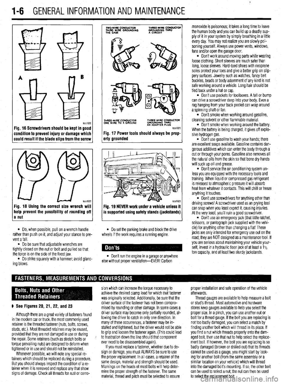
Fig. 16 Screwdrivers should be kept in good
:ondition to prevent injury or damage which
:ould result it the blade slips from the screw
0
0
PP tccs1022 Fig. 16 Using the correct size wrench will
help prevent the possibility of rounding off
a nut
7
lwo.WIRE CouDuClOR TMREE-WIRE CONO”CTOI
MIRD WIRE GROUNDING GROUNDING TNRU
THE CASE A CmxlIT
.
i$Y$$pQ
p-+
TNHREE-WIRE CONDUCTOR THREE-WIRE CONDUCTOR
ONE WIRE TO 4 GROUND GROUNOlNG TMRU
AN ADAPTER PLUG
tccm21
Fig. 17 Power tools should always be prop-
erly grounded
Fig. 19 NEVER work under a vehicle unless it
is supported using safety stands (jackstands)
l Do, when possible, pull on a wrench handle l Do set the parking brake and block the drive
rather than push on it, and adjust your stance to pre-
vent a fall. wheels if the work requires a running engine.
l Do be sure that adjustable wrenches are
tightly closed on the nut or bolt and pulled so that
the force is on the side of the fixed jaw.
l Do strike squarely with a hammer; avoid glanc-
ing blows. l Don’t run the engine in a garage or anywhere
else without proper ventilation-EVER! Carbon monoxide is poisonous; it takes a long time to leave
the human body and you can build up a deadly sup-
ply of it in your system by simply breathing in a !ittle
every day. You may not realize you are slowly poi-
soning yourself. Always use power vents, windows,
fans and/or open the garage door.
l Don’t work around moving parts while wearing
loose clothing. Short sleeves are much safer than
long, loose sleeves. Hard-toed shoes with neoprene
soles protect your toes and give a better grip on slip-
pery surfaces. Jewelry such as watches, fancy belt
buckles, beads or body adornment of any kind is not
safe working around a vehicle. Long hair should be
tied back under a hat or cap.
l Don’t use pockets for toolboxes. A fall or bump
can drive a screwdriver deep into your body. Even a
rag hanging from your back pocket can wrap around
a spinning shaft or fan.
l Don’t smoke when working around gasoline,
cleaning solvent or other flammable material.
l Don’t smoke when workrng around the battery.
When the battery is being charged, it gives off explo-
sive hydrogen gas.
l Don’t use gasoline to wash your hands; there
are excellent soaps available. Gasoline contains dan-
gerous additives which can enter the body through a
cut or through your pores. Gasoline also removes all
the natural oils from the skin so that bone dry hands
will suck up oil and grease.
l Don’t service the air conditioning system un-
less you are equipped with the necessary tools and
trainmg. When liquid or compressed gas refrigerant
is released to atmospheric pressure it will absorb
heat from whatever it contacts. This will chill or freeze
anything it touches.
l Don’t use screwdrivers for anything other than
driving screws! A screwdriver used as an prying tool
can snap when you least expect it, causing injuries.
At the very least, you’ll ruin a good screwdriver.
. Don’t use an emergency jack (that little ratchet,
scissors, or pantograph jack supplied with the vehi-
cle) for anything other than changing a flat! These
jacks are only Intended for emergency use out on the
road; they are NOT designed as a maintenance tool. If
you are serious about mamtaining your vehicle your-
self, invest in a hydraulic floor jack of at least a 1%
ton capacity, and at least two sturdy jackstands.
sion which can increase the torque necessary to proper installation and safe operation of the vehicle
achieve the desired clamp load for which that fastener afterwards.
was originally selected. Additionally, be sure that the Thread gauges are available to help measure a bolt
p See Figures 20, 21, 22, and 23 driver surface of the fastener has not been compro- or stud’s thread. Most automotive and hardware
mised by rounding or other damage. In some cases a stores keep gauges available to help you select the
Although there are a great variety of fasteners found driver surface may become only partially rounded, al- proper size. In a pinch, you can use another nut or
in the modern car or truck, the most commonly used lowing the driver to catch in only one direction. In bolt for a thread gauge. If the bolt you are replacing is
retainer is the threaded fastener (nuts, bolts, screws, many of these occurrences, a fastener may be in- not too badly damaged, you can select a match by
studs, etc.). Most threaded retainers may be reused, stalled and tightened, but the driver would not be able finding another bolt which will thread in its place. If
provided that they are not damaged in use or during to grip and loosen the fastener again. (This could lead you find a nut which threads properly onto the dam-
the repair. Some retainers (such as stretch bolts or J to frustration down the line should that component aged bolt, then use that nut to help select the replace-
torque prevailing nuts) are designed to deform when ever need to be disassembled again). ment bolt If however, the bolt you are replacing is so
tightened or in use and should not be reinstalled. If you must replace a fastener, whether due to de- badly damaged (broken or drilled out) that its threads
Whenever possible, we will note any special re- sign or damage, you must ALWAYS be sure to use cannot be used as a gauge, you might start by look-
tainers which should be replaced during a procedure. the proper replacement In all cases, a retainer of the ing for another bolt (from the same assembly or a
But you should always inspect the condition of a re- same design, material and strength should be used. similar location on your vehicle) which will thread
tainer when It is removed and replace any that show Markings on the heads of most bolts will help deter- into the damaged bolt’s mounting. If so, the other bolt
signs of damage. Check all threads for rust or corro- mine the proper strength of the fastener. The same
can be used to select a nut; the nut can then be used
material, thread and pitch must be selected to assure
to select the replacement bolt.
Page 10 of 408
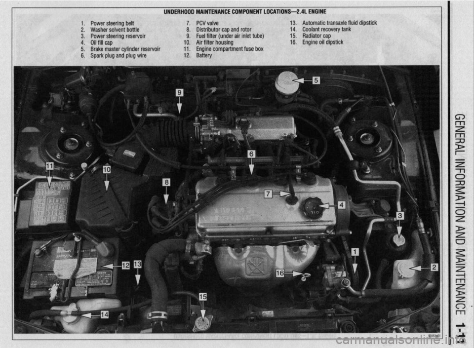
UNDERHDDD MAINTENANCE COMPONENT LOCATIONS-2AL ENGINE
II
1. Power steering belt 7. PCV valve
2. Washer solvent bottle 8. Distributor cap and rotor
3. Power steering reservoir 9. Fuel filter (under air inlet tube)
4. Oil fill cap 10. Air filter housing
5. Brake master cylinder reservoir 11. Engine compartment fuse box
6. Spark plug and plug wire 12. Battery 13. Automatic transaxle fluid dipstick
14. Coolant recovery tank
15. Radiator cap
16. Engine oil dipstick
Page 11 of 408
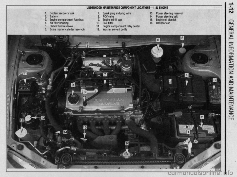
UNDERHOOD MAINTENANCE COMPONENT LOCATIONS-l .8L ENGINE
1. Coolant recovery tank
2. Battery
3. Engine compartment fuse box
4. Air filter housing
5. Clutch fluid reservoir
6. Brake master cylinder reservoir 7. Spark plug and plug wire
8. PCV valve
9. Engine oil fill cap
10. Fuel filter
11. Engine compartment relay center
12. Washer solvent bottle 13. Power steering reservoir
14. Power steering belt
15. Engine oil dipstick
16. Radiator cap
Page 15 of 408
*
l-16 GENERALINFORMATIONAND MAINTENANCE
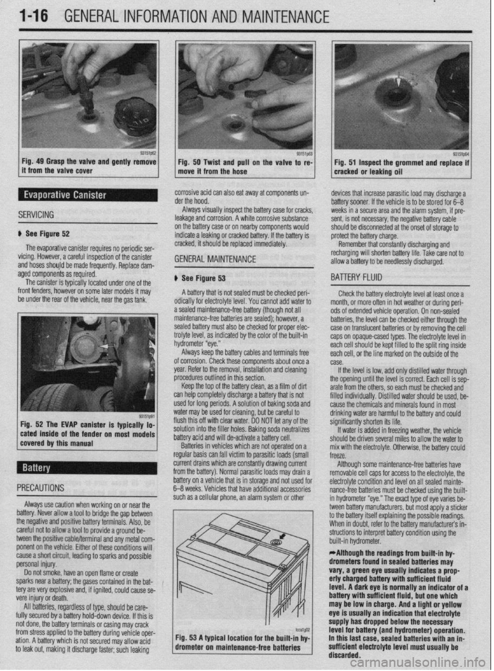
Fig. 49 Grasp the valve and gently remove
Fig. 50 Twist and pull on the valve to re-
it from the valve cover
move it from the hose Fig. 51 Inspect the grommet and replace if
cracked or leaking oil
SERVICING
corrosive acid can also eat away at components un-
der the hood.
Always visually inspect the battery case for cracks,
leakage and corrosion. A white corrosive substance
u See Figure 52
The evaporative canister requires no periodic ser-
vicing. However, a careful inspection of the canister
and hoses should be made frequently, Replace dam- on the battery case or on nearby components would
indicate a leaking or cracked battery. If the battery is
cracked, it should be replaced immediately. GENERALMAINTENANCE '_
devices that increase parasitic load may discharge a
battery sooner. If the vehicle is to be stored for 6-B
weeks in a secure area and the alarm system, if pre-
sent, is not necessary, the negative battery cable
should be disconnected at the onset of storage to
protect the battery charge.
Remember that constantly discharging and
recharging will shorten battery life. Take rare not to
allow a battery to be needlessly discharged.
aged components as required.
The canister is typically located under one of the
front fenders, however on some later models it may
be under the rear of the vehicle, near the gas tank,
r on most models # See Figure 53
A battery that is not sealed must be checked peri-
odically for electrolyte level. You cannot add water to
a sealed maintenance-free battery (though not all
maintenance-free batteries are sealed); however, a
sealed battery must also be checked for proper elec-
trolyte level, as indicated by the color of the built-in
hydrometer “eye.”
Always keep the battery cables and terminals free
of corrosion. Check these components about once a
year. Refer to the removal, installation and cleaning
procedures outlined in this section,
Keep the top of the battery clean, as a film of dirt
can help completely discharge a battery that is not
used for long periods. A solution of baking soda and
water may be used for cleaning, but be careful to
flush this off with clear water. DO NOT let any of the
solution into the filler holes. Baking soda neutralizes
battery acid and will de-activate a battery cell.
Batteries in vehicles which are not operated on a
regular basis can fall victim to parasitic loads (small
BA-ITERY FLUID
Check the battery electrolyte level at least once a
month. or more often in hot weather or during peri-
ods of extended vehicle operation. On non-sealed
batteries, the level can be checked either through the
case on translucent batteries or by removing the cell
caps on opaque-cased types. The electrolyte level in
each cell should be kept filled to the split ring inside
each ceil, or the line marked on the outside of the
case.
If the level is low, add only distilled water through
the opening until the level is correct. Each cell is sep-
arate from the others, so each must be checked and
filled individuallv. Distilled water should be used, be-
cause the chemicals and minerals found in most
drinking water are harmful to the battery and could
significantly shorten its life.
If water is added in freezing weather, the vehicle
should be driven several miles to allow the water to
mix with the electrolyte. Otherwise, the battery could
freeze.
current drains which are constantly drawing current
from the battery). Normal parasitic loads may drain a Although some maintenance-free batteries have
removable cell caos for access to the electrolyte, the
cause a short circuit, leading to sparks and possible
personal injury.
Do not smoke, have an open flame or create
sparks near a battery; the gases contained in the bat-
tery are very explosive and, if ignited, could cause se-
vere injury or death.
All batteries, regardless of type, should be care-
fully secured by a battery hold-down device. If this is
not done, the battery terminals or casing may crack
from stress applied to the battery during vehicle oper-
ation. A battery which is not secured may allow acid
to leak out, making it discharge faster; such leaking m / built-in hydrometer. .
*Although the readings from built-in hy-
drometers found in sealed batteries may
vary, a green eye usually indicates a prop
erly charged battery with sufficient fluid
level. A dark eye is normally an indicator of a
battery wlth sufficient fluid, but one which
may be low in charge. And a light or yellow
eye is usually an indication that electrolyte
supply has dropped below the necessary
tcu1@32 Fig. 53 A typical location for the built-in hv- level for battery (and hydrometer) operation.
drometer on maintenan
ce-free batteries ’ I In this last case. sealed batteries with an in-
sufficient electrolyte level must usually be
’ discarded.
Page 49 of 408
.~ P.X I_ - “, .- I .-., IS ” .~.I .r
2-2 ENGINE ELECTRICAL
nn
ity and trouble: shooting electrical circuits,
please refer to Section 6 of this manual.
I
The ignition system on the 1.5L, 1993-96 1.8L,
2.OL SOHC, 1994-98 2.4L SOHC, 3.OL SOHC, and
3.5L engines uses a pointless type distributor, whose
advance mechanism is controlled by the Engine Con-
trol Unit (ECU). On the 1.5L, 1.8L, 2.4L and 3.5L en-
gines, the distributor houses a built in ignition coil
and ignition power transistor. The 2.8L SOHC and
3.OL SOHC engines utilize a separate coil and tran-
sister assemblv.
When the ignition switch is turned ON, battery
voltage is applied to the ignition coil primary winding.
As the shaft of the distributor rotates, signals are
transmitted from the oowertrain control module to the
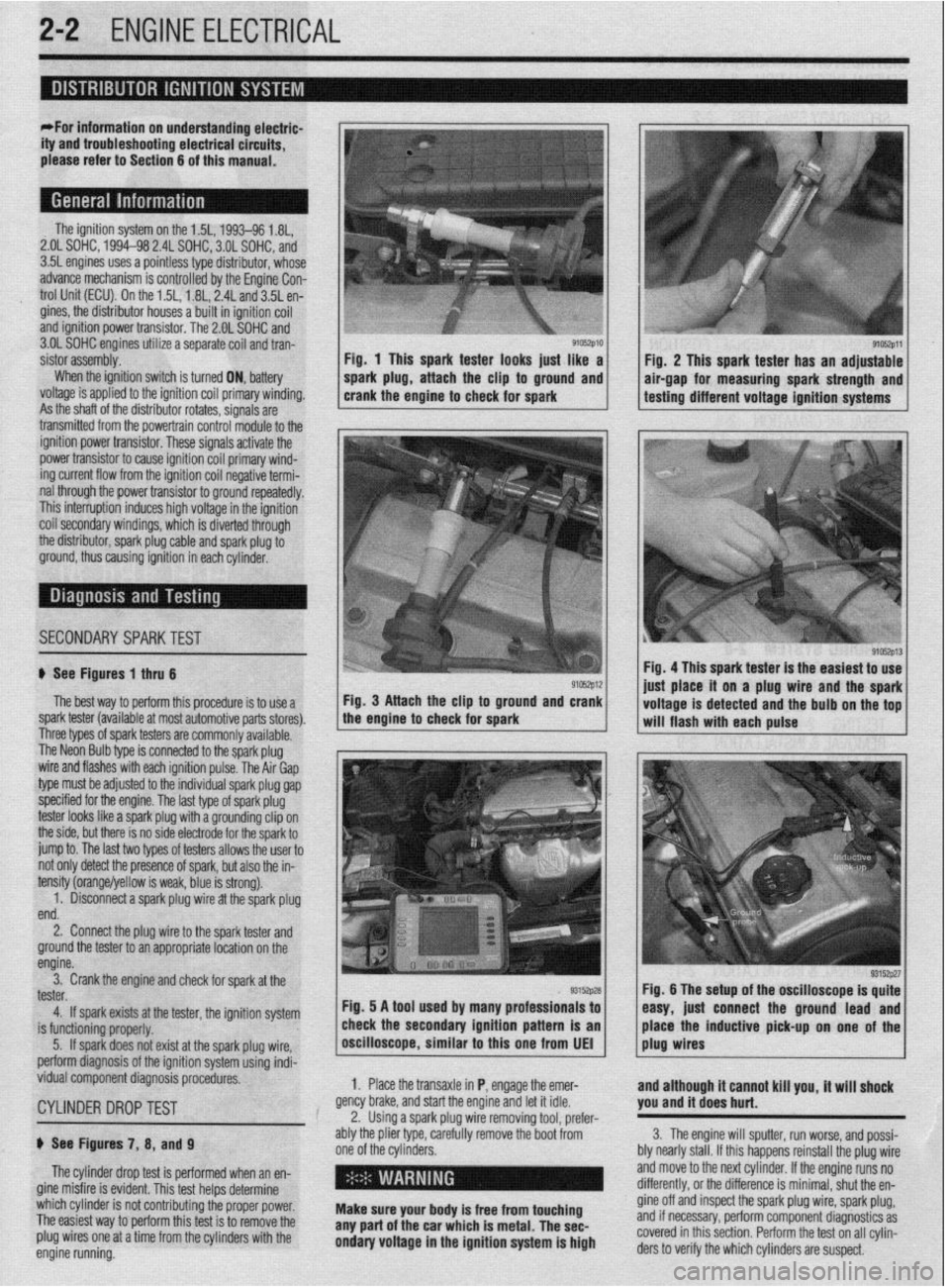
9105zp11 Fig. 1 This spark tester looks iust like a
Fiu. 2 This spark tester has an adjustable
spark plug, attach the clip to ground and air-gap for measuring spark strength and
crank the engine to check for spark testing different voltage ignition systems
.
ignition power trar rsistor. These signals activate the
power transistor to cause ignition coil primary wind-
ing current flow from the ignition coil negative termi-
nal through the power transistor to ground repeatedly.
This interruption induces high voltage in the ignition
coil secondarv windinas, which is diverted throuah
the distributor, spark plug cable and spark plug 6
ground, thus causing ignition in each cylinder.
I
SECONDARYSPARKTEST l;h.4-
! ,L ".~
'$ >,%
If See Figures 1 thru 6
91rJszp12 Fig. 4 This spark tester is the easiest to use
iust alace it on a plug wire and the spark
The best way to perform this procedure is to use a Fig. 3 Attach the clip to ground and crank
spark tester (available at most automotive parts stores). the engine to check for spark
I I voltage is detected and the bulb on the tof
-. will flash with each pulse
I nree types ot spark testers are commonly available.
The Neon Bulb type is connected to the spark plug
wire and flashes with each ignition pulse. The Air Gap
type must be adjusted to the individual spark plug gap
specified for the engine. The last type of spark plug
tester looks like a spark plug with a grounding clip on
the side, but there is no side electrode for the spark to
jump to. The last two types of testers allows the user to
not only detect the presence of spark, but also the in-
tensity (orange/yellow is weak, blue is strong).
1. Disconnect a spark plug wire at the spark plug
end.
2. Connect the plug wire to the spark tester and
ground the tester to an appropriate location on the
engine.
3. Crank the engine and check for spark at the
tester.
4. If spark exists at the tester, the ignition system
is functioning properly.
5. If spark does not exist at the spark plug wire,
perform diagnosis of the ignition system using indi-
vidual component diagnosis procedures,
CYLINDER DROPTEST
p See Figures 7, 8, and 9
The cylinder drop test is performed when an en-
gine misfire is evident. This test helps determine
which cylinder is not contributing the proper power.
The easiest way to perform this test is to remove the
plug wires one at a time from the cylinders with the
engine running. 1. Place the transaxle in P, engage the emer-
gency brake, and start the engine and let it idle.
2. Using a spark plug wire removing tool, prefer-
ably the plier type, carefully remove the boot from
one of the cylinders.
i ’
Make sure your body is free from touching
any part of the car which is metal. The sec-
ondary voltage in the ignition system is high and although it cannot kill you, it will shock
you and it does hurt.
3. The engine will sputter, run worse, and possi-
bly nearly stall. If this happens reinstall the plug wire
and move to the next cylinder. If the engine runs no
differently, or the difference is minimal, shut the en-
gine off and inspect the spark plug wire, spark plug,
and if necessary, perform component diagnostics as
covered in this section. Perform the test on all cylin-
ders to verify the which cylinders are suspect.
Page 58 of 408
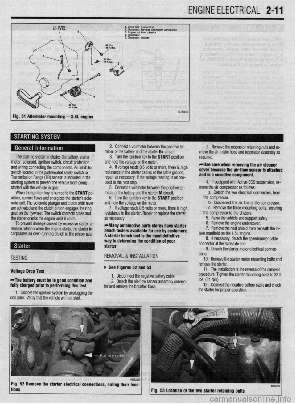
ENGINE ELECTRICAL 2-11
l.unVeMlil(GSflWtWJ
2.Gwwator harness con- connectk,,,
3. Engme OS, level d,pst,&
4 Generator
Fig. 51 Alternator mounting -3.51 engine
The starting system includes the battery, starter
motor, solenoid, ignition switch, circuit protection
and wiring connecting the components. An inhibitor
switch located in the park/neutral safety switch or
Transmission Range (TR) sensor is included in the
starting system to prevent the vehicle from being
started with the vehicle in gear.
When the ignition key is turned to the START po-
sition, current flows and energizes the starters sole-
noid coil. The solenoid plunger and clutch shift lever
are activated and the clutch pinion engages the ring
gear on the flywheel. The switch contacts close and
the starter cranks the engine until it starts.
To prevent damage caused by excessive starter ar-
mature rotation when the engine starts, the starter in-
corporates an over-running clutch in the pinion gear. 2. Connect a voltmeter between the positive ter-
minal of the battery and the starter B+ circuit.
3. Turn the ignition key to the START position
and note the voltage on the meter.
4. If voltage reads 0.5 volts or more, there is high
resistance in the starter cables or the cable ground,
repair as necessary. If the voltage reading is ok pro-
teed to the next step.
5. Connect a voltmeter between the positive ter-
minal of the battery and the starter M circuit,
6. Turn the ignition key to the START position
and note the voltage on the meter.
7. If voltage reads 0.5 volts or more, there is high
resistance in the starter. Repair or replace the starter
as necessary.
*Many automotive parts stores have starter
bench testers available for use by customers.
A starter bench test is the most definitive
way to determine the condition of your
starter. 3. Remove the resonator retaining nuts and re-
move the air intake hose and resonator assembly as
required.
rllse care when removing the air cleaner
cover because the air-flow sensor is attached
and is a sensitive component.
4. If equipped with Active-ECS suspension, re-
move the air compressor as follows:
a. Detach the two electrical connectors, from
the compressor.
b. Disconnect the air line at the compressor.
c. Remove the three mounting bolts, securing
the compressor to the chassis.
5. Raise the vehicle and support safely.
6. Remove the engine undercover.
7. Remove the heat shield from beneath the in-
take manifold on the 1.5L engine.
8. If necessary, detach the speedometer cable
connector at the transaxle end.
9. Detach the starter motor electrical connac-
TESTING
Voltage Drop Test
*The battery must be in good condition and
fully charged prior to performing this test. REMOVAL&INSTALLATION
# See Figures 52 and 53
1. Disconnect the negative battery cable.
2. Detach the air-flow sensor assembly connec-
tor and remove the breather hose.
1. Disable the ignition system by unplugging the
coil pack. Verify that the vehicle will not start. tions.
10. Remove the starter motor mounting bolts and
remove the starter.
11. The installation is the reverse of the removal
procedure. Tighten the starter mounting bolts to 22 ft.
Ibs. (31 Nm).
12. Connect the negative battery cable and check
the starter for proper operation.
9315zp19 Fig. 53 Location of the two starter retaining bolts
Page 66 of 408
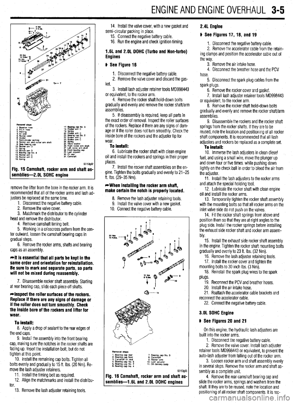
ENGINEANDENGINEOVERHALJL 3-5
Fig. 15 Camshaft, rocker arm and shaft as-
remblies-2.01 SOHC engine
remove the lifter from the bore in the rocker arm. It is
recommended that all of the rocker arms and lash ad-
justers be replaced at the same time.
1. Disconnect the negative battery cable.
2. Remove the valve cover.
3. Matchmark the distributor to the cylinder
head and remove the distributor.
4. Remove camshaft timing belt.
5. Working in a crisscross pattern from the cen-
ter outward, loosen the camshaft bearing caps in
gradual steps.
6. Remove the rocker arms, shafts and bearing
caps as an assembly.
*It is essential that all parts be kept in the
same order and orientation for reinstallation.
Be sure to mark and separate parts, so parts
will not be mixed during reassembly.
7. Disassemble rocker shaft assembly. Starting
at rear bearing cap, slide each piece off shafts.
*Inspect the roller surfaces of the rockers.
Replace if there are any signs of damage or
if the roller does not turn smoothly. Check
the inside bore of the rockers and lifter for
wear.
To install:
8. Apply a drop of sealant to the rear edges of
the end caps.
9. Install the assembly into the front bearing
cap, making sure the notches in the rocker shafts are
facing up. Insert the installation bolt, but do not
tighten at this point.
10. Install the remaining cap bolts. Tighten all
bolts evenly and gradually to 15 ft. Ibs. (20 Nm). Re-
move the lash adjuster retainers.
11. Install the timing belt as required.
12. Align the matchmarks and install the distribu-
tor.
13. Remove the lash adjuster retaining tools. 14. Install the valve cover, with a new gasket and
semi-circular packing in place.
15. Connect the negative battery cable.
16. Run the engine and check ignition timing.
1.6L and 2.OL DOHC (Turbo and Non-turbo)
Engines
6 See Figure 16
1. Disconnect the negative battery cable.
2. Remove the valve cover and discard the gas-
ket.
3. Install lash adjuster retainer tools MD998443
or equivalent, to the rocker arm.
4. Remove the rocker shaft hold-down bolts
gradually and evenly and remove the rocker shaft/arm
assemblies.
5. If disassembly is required, keep all parts in
the exact order of removal. Inspect the roller surfaces
of the rockers. Replace if there are any signs of dam-
age or if the roller does not turn smoothly. Check the
inside bore of the rockers and the adjuster tip for
wear.
To install: 6. Lubricate the rocker shaft with clean engine
oil and install the rockers and springs in their proper
places.
7. Install the rocker shaft assemblies on the en-
gine. Tighten the bolts gradually and evenly to 21-25
ft. Ibs. (29-35 Nm).
*When installing the rocker arm shaft,
make certain the notch is properly located.
8. Remove the lash adiuster retainina tools
9. Install the valve cover with a new gasket.
10. Connect the negative battery cable.
F :ig. 16 Camshaft, rocker arm and shaft as
s iemblies-1.6L and 2.OL DOHC engines
*o Nm
IILlbs -
9315390 3
2.4L Engine
# See Figures 17, 16, and 19
1. Disconnect the negative battery cable.
2. Remove the accelerator cable from the retain-
ing clamps and position the accelerator cable out of
the way.
3. Remove the air intake hose.
4. Disconnect the breather hose and the PCV
hose.
5. Disconnect the spark plug cables from the
spark plugs.
6. Remove the rocker cover and gasket.
7. Install lash adjuster retainer tools MD998443
or equivalent, to the rocker arm.
8. Remove the rocker shaft hold-down bolts
gradually and evenly and remove the rocker shaft/arm
assemblies.
9. Disassemble the rockers and the rocker shaft
springs from the rocker shafts. If they are to be
reused, note the location and positionrng of all rocker
shaft components. It is recommended that all lash
adjusters and rockers be replaced as a complete set.
To install: 10. Immerse the lash adjusters in clean diesel
fuel, and using a small wire, move the plunger up
and down four or five times. while pushing down
lightly on the check ball in order to bleed the air from
the adjuster.
11. Install the lash adjusters to the rocker arms
and attach the special holding tool.
12. Lubricate the rocker shaft with clean engine
oil and install the rocker arms.
13. Temporarily tighten the rocker shaft assembly
with the mounting bolts so that all rocker arms on the
inlet valve side do not push on the valves,
14. Fit the rocker shaft springs from above and
position them so that they are at right angles to the
plug side. Install the rocker springs before installing
the exhaust side rocker shaft and rocker arm assem-
bly.
15. Install the exhaust side rocker shaft assembly
in the engine. Tighten the rocker shaft mounting bolts
gradually and evenly to 23 ft. Ibs. (32 Nm).
16. Remove the lash adjuster retaining tools.
17. Install the rocker cover and tighten the
mounting bolts to 30 inch Ibs. (3 Nm).
18. Reinstall the spark plug wires to the spark
plugs.
19. Reconnect the PCV and breather hoses.
20. Install the air intake hose.
21. Reattach the accelerator cable brackets and
reconnect the accelerator cable.
22. Connect the negative battery cable.
3.OL SOHC Engine
6 See Figures 20 and 21
On this engine, the hydraulic lash adjusters are
built into the rocker arms,
1. Disconnect the negative battery cable.
2. Remove the valve cover. Install lash adjuster
retainer tools MD998443 or equivalent, to prevent the
auto-lash adjuster from falling out of the rocker arm.
3. Loosen rocker arm and shaft assembly evenly
in several steps. Remove the rocker arm and shaft as-
sembly as a complete unit.
4. Remove the rear camshaft bearing cap and
slide the rocker arms, springs and washers from the
shaft. If they are to be reused, note the location and
positioning of all rocker shaft components. It is rec-
Page 68 of 408
ENGINEANDENGINEOVERHAUL 3-7
4. Remove the center cover, breather and PCV
hoses, and spark plug cables.
5. Remove the rocker cover.
6. Remove the throttle body stay, both camshaft
sprockets, and oil seals.
7. Remove the Camshaft Position fCMP) sensor 3. install the lash adjuster clips on the rocker
arms, then loosen the bearing cap bolts. Do not re-
move the bolts from the bearing caps.
4. Remove the rocker arms, shafts and bearing
caps as an assembly.
lo hlstall: unless it is contaminated or is several years old.
3. Remove any necessary components to access
the thermostat.
4. Remove the thermostat housinq retaininq
nd adapter from the rear of the camshah. ’
8. Remove the intake and exhaust camshafts.
9. Remove rocker arms and lash adjusters from
he head. It is recommended that all lash adjusters
md rockers be replaced as a complete set.
To Install:
10. Immerse the lash adjusters in clean diesel
uel. Using a small wire, move the plunger of the lash
tdjuster up and down four or five times while push-
ng down lightly on the check ball in order to bleed
jut the air. Lubricate and install the lash adjusters in
he cylinder head.
11. Lubricate the camshafts with clean enqine oil
nd position the camshafts on the cylinder head.
12. Install the bearing caps. Tighten the caps in
sequence, in 2 or 3 steps. Caps 2,3 and 4 have a
ront mark. Install with the mark aligned with the front
nark on the cylinder head. Intake caps have I
stamped on the cap and exhaust caps have E. Also,
)e sure the rocker arm is correctly mounted on the
ash adjuster and the valve stem end. Torque the front
md rear retaining cap bolts to 14 ft. Ibs. (20 Nm) and
ighten the center 3 retaining cap bolts to 8 ft. Ibs.
11 Nm).
13. Apply a coating of engine oil to the oil seals
md install.
14. Install the timing belt, valve cover and all re-
ated parts. Refer to the timing belt procedure in this
;ection. 5. Install the bearing caps/rocker arm assem-
blies. Tighten the bolts to 23 ft. Ibs. (31 Nm).
6. Remove the lash adjuster clips.
7. Install the rocker arm cover using a new gas-
ket.
8. Connect the negative battery cable.
REMOVAL &INSTALLATION
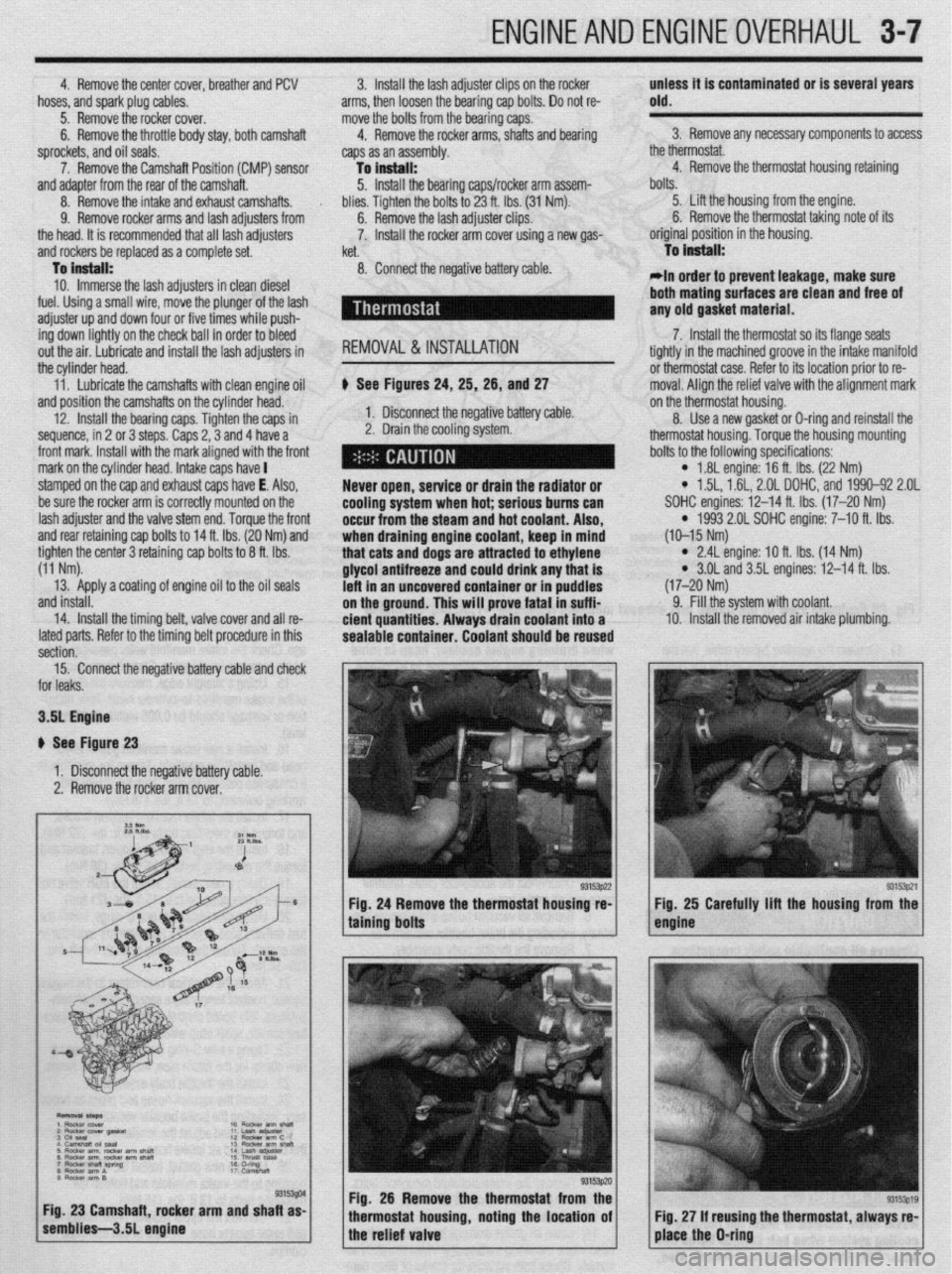
b See Figures 24, 25, 26, and 27
1. Disconnect the negative battery cable.
2. Drain the cooling system.
Never open, service or drain the radiator or
cooling system when hot; serious bums can
occur from the
steam and hot coolant. Also,
when draining engine coolant, keep in mind
that cats and dogs are attracted to ethylene
glycol antifreeze and could drink any that is
left in an uncovered container or in puddles
on the ground. This will prove fatal in suffi-
cient quantities. Always drain coolant into a
sealable container. Coolant should be reused bolts.
5. Lift the housing from the engine.
6. Remove the thermostat taking note of its
original position in the housing.
To Install:
*In order to prevent leakage, make sure
both mating
surfaces are clean and free of
any old gasket material.
7. Install the thermostat so its flange seats
tightly in the machined groove in the intake manifold
or thermostat case. Refer to its location prior to re-
moval. Aliqn the relief valve with the alignment mark
on the thermostat housing.
8. Use a new gasket or D-ring and reinstall the
thermostat housing. Torque the housing mounting
bolts to the following specifications:
l 1.8L engine: 16 ft. Ibs. (22 Nm) l 1.5L, 1.61, 2.OL DOHC, and 1990-92 2.OL
SOHC engines: 12-14 ft. Ibs. (17-20 Nm)
l 1993 2.01 SOHC engine: 7-10 ft. Ibs.
(10-15 Nm)
l 2.4L engine: IO ft. Ibs. (14 Nm) l 3.OL and 3.5L engines: 12-14 ft. Ibs.
(17-20 Nm)
9. Fill the system with coolant.
10. Install the removed air intake plumbing.
15. Connect the negative battery cable and check
or leaks.
3.51 Engine
I See Figure 23
1. Disconnect the negative battery cable.
2. Remove the rocker arm cover.
g. 26 Remove the thermostat from the
ousing, noting the location of using the thermostat, always re-