1900 MITSUBISHI DIAMANTE battery location
[x] Cancel search: battery locationPage 293 of 408
7-14 DRIVETRAIN
The only model covered by this manual equipped
with a transfer case is the 1990-93 AWD Galant. assembly. Place a drain pan under the rear of the
transfer assembly to catch any fluid that leaks out.
3. Usinq a flat-bladed prying tool, carefully re-
REMOVAL &INSTALLATION
move the ofi seal from the transfer dust seal guard
To install: 4. Using proper size seal driver tool, install the
seal into the dust seal quard and the transfer assem-
blv.
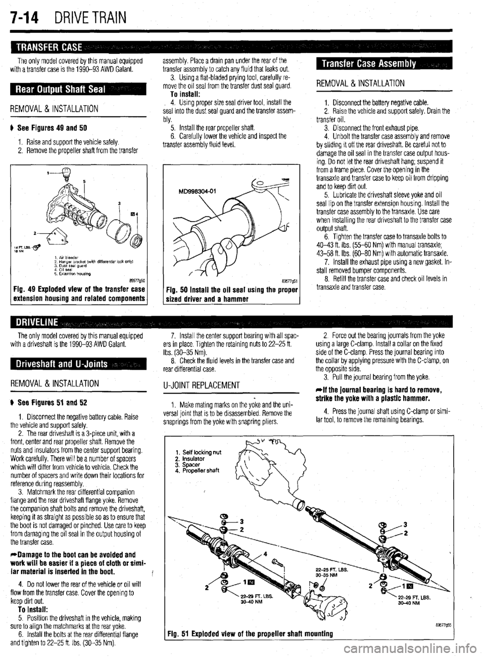
# See Figures 49 and 50
1. Raise and support the vehicle safely.
2. Remove the propeller shaft from the transfer ‘5. Install the rear propeller shaft.
6. Carefully lower the vehicle and inspect the
transfer assembly fluid level.
a9577g50 1 Fig. 49 Exploded view of the transfer case
1 extension housing and related components a9577g51 Fig. 50 Install the oil seal using the proper
sized driver and a hammer REMOVAL &INSTALLATION
1. Disconnect the battery negative cable.
2. Raise the vehicle and support safely. Drain the
transfer oil.
3. Disconnect the front exhaust pipe.
4. Unbolt the transfer case assembly and remove
by sliding it off the rear driveshaft. Be careful not to
damage the oil seal in the transfer case output hous-
ing. Do not let the rear driveshaft hang; suspend it
from a frame piece. Cover the opening in the
transaxle and transfer case to keep oil from dripping
and to keep dirt out.
5. Lubricate the driveshaft sleeve yoke and oil
seal lipan the transfer extension housing. Install the
transfer case assembly to the transaxle. Use care
when installing the rear driveshaft to the transfer case
output shaft.
6. Tighten the transfer case to transaxle bolts to
40-43 ft. Ibs. (55-60 Nm) with manual transaxle;
43-58 ft. Ibs. (60-80 Nm) with automatic transaxle.
7. Install the exhaust pipe using a new gasket. In-
stall removed bumper components.
8. Refill the transfer case and check oil levels in
transaxle and transfer case.
The only model covered by this manual equipped
with a driveshaft is the 1990-93 AWD Galant.
REMOVAL &INSTALLATION
) See Figures 51 and 52
1. Disconnect the negative battery cable. Raise
the vehicle and support safely.
2. The rear driveshaft is a 3-piece unit, with a
front, center and rear propeller shaft. Remove the
nuts and msulators from the center support bearing.
Work carefully. There will be a number of spacers
which will differ from vehicle to vehicle. Check the
number of spacers and write down their locations for
reference during reassembly.
3. Matchmark the rear differential companion
flange and the rear driveshaft flange yoke. Remove
the companion shaft bolts and remove the driveshaft,
keeping it as straight as possible so as to ensure that
the boot is not damaged or pinched. Use care to keep
from damaging the oil seal in the output housing of
the transfer case.
*Damage to the boot can be avoided and
work will be easier if a piece of cloth or simi-
lar material is inserted in the boot.
4. Do not lower the rear of the vehicle or oil will
flow from the transfer case. Cover the opening to
keep dirt out.
To install: 5. Position the driveshaft in the vehicle, making
sure to align the matchmarks at the rear yoke.
6. Install the bolts at the rear differential flange
and tighten to 22-25 ft. Ibs. (30-35 Nm). 7. Install the center support bearing with all spac- 2 Force out the bearing journals from the yoke
ers in place. Tighten the retaining nuts to 22-25 ft. using a large C-clamp. Install a collar on the fixed
Ibs. (3C-35 Nm). side of the C-clamp. Press the journal bearing into
8. Check the fluid levels in the transfer case and the collar by applying pressure with the C-clamp, on
rear differential case. the opposite side.
U-JOINTREPLACEMENT
1. Make mating marks on the yoke and the uni-
versa1 joint that is to be disassembled. Remove the
snaprings from the yoke with snapring pliers. 3. Pull the journal bearing from the yoke.
rlf the journal bearing is hard to remove,
strike the yoke with a plastic hammer.
4. Press the journal shaft using C-clamp or simi-
lar tool, to remove the remaining bearings.
Fiu. 51 Exploded view of the proueller shafl mounting
Page 342 of 408
.
9-6 BRAKES
REMOVAL & INSTALLATION
I) See Figure 2
1. Disconnect the negative battery cable.
2. Locate the proportioning valve, usually below
the master cylinder.
3. Tag and disconnect the brake lines from the
valve.
Brake fluid contains poiygiycoi ethers and
poiygiycois. Avoid contact with the eyes and
wash your hands thoroughly after handling
brake fluid. if you do get brake fluid in your
eyes, flush your eyes with clean, running wa-
ter for 15 minutes. if eye irritation persists,
or if you have taken brake fluid internally,
IMMEDIATELY seek medical assistance.
4. Remove the proportioning valve from the en-
gine compartment.
To install:
5. The installation is the reverse of the removal
procedure. Bleed the brakes in the following order:
6. Diamante
a. Right rear caliper
b. Left front caliper
c. Left rear caliper
d. Right front caliper
7. Mirage and Gaiant
a. Left rear wheel cylinder or caliper
b. Right front cylinder
c. Right rear wheel cylinder or caliper
d. Left front caliper
8. Connect the negative battery cable and check
the brakes for proper operation.
Clean, high quality brake fluid is essential to
the safe and proper operation of the brake
system. You should always buy the highest
quality brake fluid that is available. if the
brake fluid becomes contaminated, drain and
flush the system, then refill the master cyiin-
der with new fluid. Never reuse any brake
fluid. Any brake fluid that is removed from
the system should be discarded. Also, do not
allow any brake fluid to come in contact with
a painted surface; it will damage the paint.
Metal lines and rubber brake hoses should be
checked frequently for leaks and external damage.
Metal lines are particularly prone to crushing and
kinking under the vehicle. Any such deformation can
restrict the proper flow of fluid and therefore impair
braking at the wheels. Rubber hoses should be
checked for cracking or scraping; such damage can
create a weak spot in the hose and it could fail under
pressure.
Any time the lines are removed or disconnected,
extreme cleanliness must be observed. Clean all
joints and connections before disassembly (use a stiff bristle brush and clean brake fluid); be sure to
plug the lines and ports as soon as they are opened.
New lines and hoses should be flushed clean with
brake fluid before installation to remove any contami-
nation. REMOVAL&INSTALLATION
) See Figures 16, 17, 18, and 19
1. Disconnect the negative battery cable.
2. Raise and safely support the vehicle on jack-
stands.
3. Remove any wheel and tire assemblies nec-
essary for access to the particular line you are remov-
ing.
4. Thoroughly clean the surrounding area at the
joints to be disconnected.
5. Place a suitable catch pan under the joint to
be disconnected.
6. Using two wrenches (one to hold the joint
and one to turn the fitting), disconnect the hose or
line to be replaced.
7. Disconnect the other end of the line or hose,
moving the drain pan if necessary. Always use a
back-up wrench to avoid damaging the fitting.
8. Disconnect any retaining clips or brackets
holding the line and remove the line from the vehicle.
-if the brake system is to remain open for
more time than it takes to swap lines, tape or
plug each remaining clip and port to keep
contaminants out and fluid in.
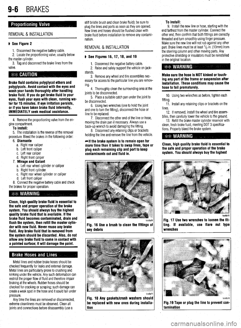
I tcca9p09 tcca9p09 Fig. 16 Use a brush to clean the fittings of Fig. 16 Use a brush to clean the fittings of
any debris any debris
tcca9pll Fig. 18 Any gaskets/crush washers should
be replaced with new ones during instaiia-
tion To install:
9. Install the new line or hose, starting with the
end farthest from the master cylinder. Connect the
other end, then confirm that both fittings are correctly
threaded and turn smoothly using finger pressure.
Make sure the new line will not rub against any other
part. Brake lines must be at least l/z in. (13mm) from
the steering column and other moving parts. Any
protective shielding or insulators must be reinstalled
in the original location.
Make sure the hose is NOT kinked or touch-
ing any part of the frame or suspension after
installation. These conditions may cause the
hose to fail prematurely.
10. Using two wrenches as before, tighten each
fitting.
Ii. Install any retaining clips or brackets on the
lines.
12. If removed, install the wheel and tire assem-
blies, then carefully lower the vehicle to the ground.
13. Refill the brake master cylinder reservoir with
clean, fresh brake fluid, meeting DOT 3 specifica-
tions. Properly bleed the brake system.
Clean, high quality brake fluid is essential to
the safe and proper operation of the brake
system. You should always buy the highest
tcca9p10 Fig. 17 Use two wrenches to loosen the fit-
ting. If available, use flare nut type
wrenches
tcca9p12 Fig.19 Tape or plug the line to prevent con-
tamination
Page 370 of 408
IO-2 BODYANDTRIM
6. Remove the hinge bolts and remove the door
assembly.
REMOVAL &INSTALLATION To install:
7. Position the door into place and finger
ti See Figures 1, 2, and 3
*This procedure applies to both the front
and rear doors.
1. Disconnect the negative battery cable.
2. Support the door, by placing a floor jack and
.a piece of wood underneath the door.
3. Remove the bolts from the door check arm.
4. Rotate the collar on the main wiring harness
connector to unplug it. Unplug any other applicable
wiring connectors.
5. Matchmark the location of the hinges on the
door. tighten the hinge bolts.
s 8. Align the door with the hinge marks made
earlier and tighten the bolts, as follows:
’
a. 1990-92 Mirage and 1990-93 Galant:
12-19 ft. Ibs. (6l7,26 Nm&
b. 1993-9 Mirage, 1 94-00 Galant and all
Diamante: 16 ft. Ibs. (22 Nm)
c. 1997-00 Mirage: 20 ft. Ibs. (27 Nm)
9. Attach the wiring connectors.
IO. Attach the door check arm and tighten the re-
taining bolts.
II. Remove the supporting jack.
12. Connect the negative battery cable.
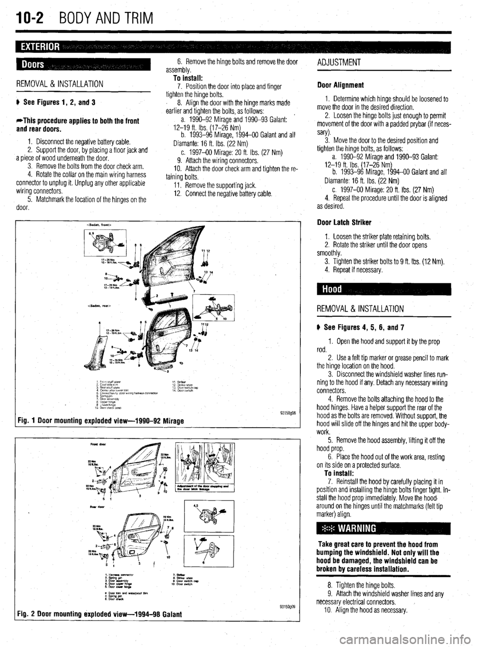
Fig. 1 Door mounting exploded view-1990-92
Mirage 9315oQo8
9315oQog 1
Fig. 2 Door mounting ixploded view-1994-98 Galanf ADJUSTMENT
Door Alignment
1. Determine which hinge should be loosened to
move the door in the desired direction.
2. Loosen the hinge bolts just enough to permit
movement of the door with a padded prybar (if neces-
sary).
3. Move the door to the desired position and
tighten the hinge bolts, as follows:
a. 1990-92 Mirage and 1990-93 Galant:
12-19 ft. Ibs. ($7-26 Nmg
b. 1993-9 Mirage, 1 94-00 Galant and all
Diamante: 16 ft. Ibs. (22 Nm)
c. 1997-00 Mirage: 20 ft. Ibs. (27 Nm)
4. Repeat the procedure until the door is aligned
as desired.
Door Latch Striker
1. Loosen the striker plate retaining bolts.
2. Rotate the striker until the door opens
smoothly.
3. Tighten the striker
bolts to 9 ft. Ibs. (12 Nm).
4. Repeat if necessary.
REMOVAL & INSTALLATION
ti See Figures 4, 5, 6, and 7
1, Open the hood and support it by the prop
rod.
2. Use a felt tip marker or grease pencil to mark
the hinge location on the hood.
3. Disconnect the windshield washer lines run-
ning to the hood if any. Detach any necessary wiring
connectors.
4. Remove the bolts attaching the hood to the
hood hinges. Have a helper support the rear of the
hood as the bolts are removed. Without support, the
hood will slide off the hinges and hit the upper body-
work.
5. Remove the hood assembly, lifting it off the
hood prop.
6. Place the hood out of the work area, resting
on its side on a protected surface.
To install: 7. Reinstall the hood by carefully placing it in
position and instaliing the hinge bolts finger tight. In-
stall the hood prop immediately. Move the hood.
around on the hinges until the matchmarks (felt tip
marker) align.
Take great care to prevent the hood from
bumping the windshield. Not only will the
hood be damaged, the windshield can be
broken by careless installation.
8. Tighten the hinge bolts.
9. Attach the windshield washer lines and any
necessary electrical connectors. )
IO. Align the hood as necessary.
Page 374 of 408
IO-6 BODYANDTRIM
1994-98 Galant .
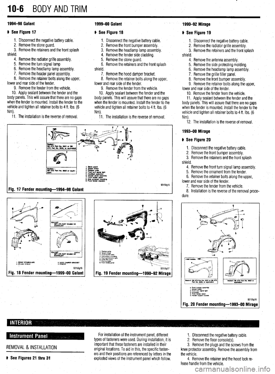
I) See Figure 17
1. Disconnect the negative battery cable.
2. Remove the stone guard. -
3. Remove the retainers and the front splash
shield.
4. Remove the radiator grille assembly.
5. Remove the turn signal lamp
6. Remove the headlamp lamp assembly.
7. Remove the header panel assembly.
8. Remove the retainer bolts along the upper,
lower and rear side of the fender.
9. Remove the fender from the vehicle.
10. Apply sealant between the fender and the
body panels, This will assure that there are no gaps
when the fender is mounted. Install the fender to the
vehicle and tighten all retainer bolts to 4 ft. Ibs. (6
Nm).
I
L
1999-00 Galant
I) See Figure 18
1. Disconnect the negative battery cable.
2. Remove the front bumper assembly.
3. Remove the headlamp lamp assembly.
4. Remove the fender side cladding.
I 5. Remove the stone guard.
6. Remove the retainers and the front splash
shield.
7. Remove the hood damper bracket.
8. Remove the retainer bolts along the upper,
lower and rear side of the fender.
9. Remove the fender from the vehicle.
10. Apply sealant between the fender and the
body panels. This will assure that there are no gaps
when the fender is mounted. Install the fender to the
vehicle and tighten all retainer bolts to 4 ft. Ibs. (6
Nm).
i 1. The installation is the reverse of removal. 11. The installation is the reverse of removal.
Fig. 17 Fender mounting-1994-98 Galant
9315Og16 Fig. 18 Fender mounting-1999-00 Galant
Fig. 19 Fender mounting-1990-92 Mirage 93150917
1990-92 Mirage
+ See Figure 19
1. Disconnect the negative battery cable.
2. Remove the radiator grille assembly.
3. Remove the retainers and the front splash
shield.
4. Remove the antenna assembly.
5. Remove the side protecting molding.
6. Remove the headlamp lamp assembly. a
7. Remove the grille filler panel.
8. Remove the front bumper assembly.
9. Remove the retainer bolts along the upper,
lower and rear side of the fender.
IO. Remove the fender from the vehicle. ~
11. Apply sealant between the fender
and the
body panels. This will assure that there are no gaps
when the fender is mounted. Install the fender to the
vehicle and tighten all retainer bolts to 4 ft. Ibs. (6
Nm).
12. The installation is the reverse of removal.
1993-00 Mirage
b See Figure 20
I. Disconnect the negative battery cable.
2. Remove the front bumper assembly.
3. Remove the retainers and the front splash
shield.
4. Remove the front turn signal lamp assembly.
5. Remove the ornament from the fender.
6. Remove the retainer bolts along the upper,
lower and rear side of the fender.
7. Remove the fender from the vehicle.
8. Installation is the reverse of the removal proce-
dure.
l Font bummer pISeWtbly 1 Splash shield
; !$yum~ slgwl l!gM 4. From lander panal
5Fenderswtlbracket 93150918 Fig. 20 Fender mounting-1993-00 Mirage
REMOVAL &INSTALLATION
6 See Figures 21 thru 31
For installation of the instrument panel, different
types of fasteners were used. During installation, it is
important that these fasteners are installed in their
original locations. To aid in this, the specific fasten-
ers and their positions are referenced by letters in the
exploded views of the instrument panel which follow. 1. Disconnect the negative battery cable.
2. Remove the floor console(s).
3. Remove the plugs and the screws from the
knee protector assembly. Remove the assembly from
the vehicle.
4. Remove the retainer and the hood lock re-
lease handle from the vehicle.
Page 384 of 408
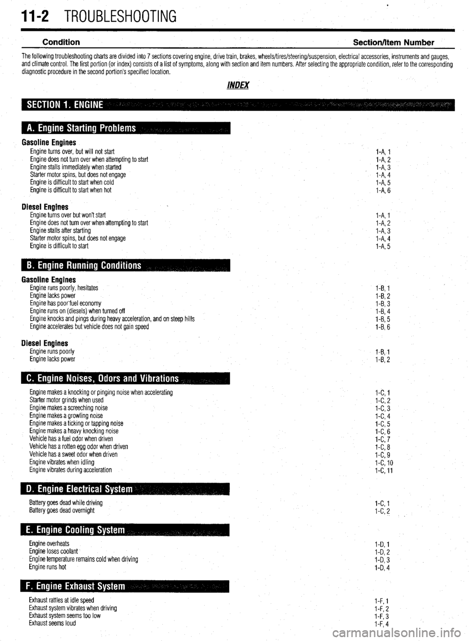
11-2 TROUBLESHOOTING
Condition
Section/Item Number
The following troubleshooting charts are divided into 7 sections covering engine, drive train, brakes, wheels/tires/steering/suspension, electrical accessories, instruments and gauges,
and climate control. The first portion (or index) consists of a list of symptoms, along with section and item numbers. After selecting the appropriate condition, refer to the corresponding
diagnostic procedure in the second portion’s specified location.
INDEX
Gasoline Engines Engine turns over, but will not start
Engine does not turn over when attempting to start
Engine stalls immediately when started
Starter motor spins, but does not engage
Engine is difficult to start when cold
Engine is difficult to start when hot
Diesel Engines Engine turns over but won’t start
Engine does not turn over when attempting to start
Engine stalls after starting
Starter motor spins, but does not engage
Engine is difficult to start I-A, 1
l-A, 2
I-A, 3
I-A, 4
I-A, 5
I-A, 6
I-A, 1
l-A, 2
I-A, 3
I-A, 4
l-A, 5
Gasoline Engines Engine runs poorly, hesitates
Engine lacks power
Engine has poorfuel economy
Engine runs on (diesels) when turned off
Engine knocks and pings during heavy acceleration, and on steep hills
Engine accelerates but vehicle does not gain speed
Diesel Engines Engine runs poorly
Engine lacks power l-B, 1
I-B, 2
l-B, 3
I-B, 4
l-B, 5
I-B, 6
l-B,-1
l-B, 2
Engine makes a knocking or pinging noise when accelerating
Starter motor grinds when used
Engine makes a screeching noise
Engine makes a growling noise
Engine makes a ticking or tapping noise
Engine makes a heavy knocking noise
Vehicle has a fuel odor when driven
Vehicle has a rotten egg odor when driven
Vehicle has a sweet odor when driven
Engine vibrates when idling
Engine vibrates during acceleration
Battery goes dead while driving
Battery goes dead overnight
Engine overheats
Engine loses coolant
Engine temperature remains cold when driving
Engine runs hot
Exhaust rattles at idle speed
Exhaust system vibrates when driving
Exhaust system seems too low
Exhaust seems loud l-C, 1
l-C, 2
l-C, 3
I-C, 4
l-C, 5
I-C, 6
l-C, 7
l-C, 8
I-C, 9
I-C, 10
l-C, 11
l-C, 1
I-C, 2
I-D, 1
I-D, 2
I-D, 3
I-D, 4
l-F, 1
l-F, 2
I-F, 3
I-F, 4
Page 396 of 408
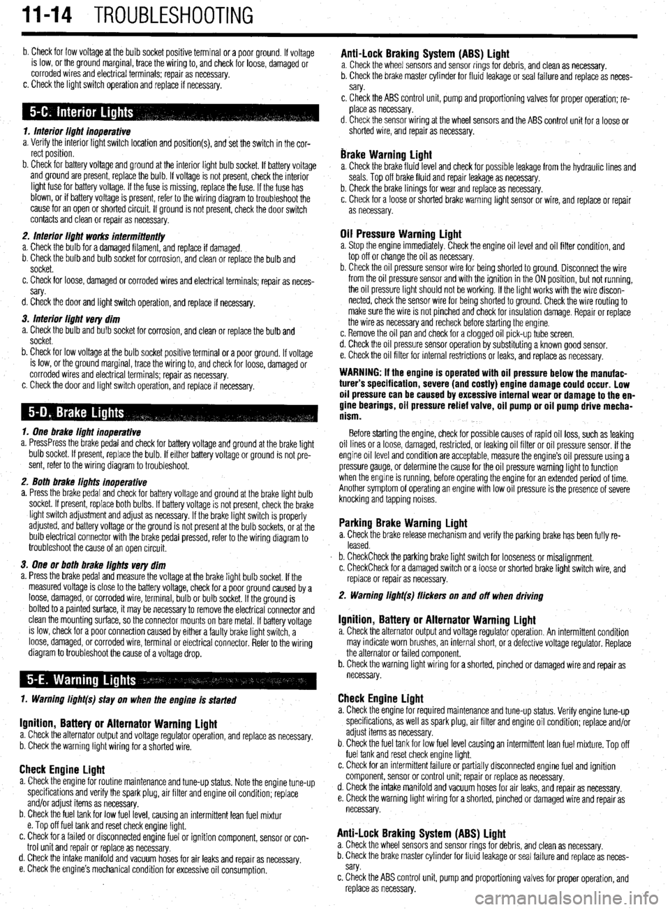
II-14 TROUBLESHOOTING
b. Check for low voltage at the bulb socket positive terminal or a poor ground. If voltage
is low, or the ground marginal, trace the wiring to, and check for loose, damaged or
corroded wires and electrical terminals; repair as necessary.
c. Check the light switch operation and replace if necessary.
1. Interior light inoperative
a. Verify the interior light switch location and position(s), and set the switch in the cor-
rect position.
b. Check for battery voltage and ground at the interior light bulb socket. If battery voltage
and ground are present, replace the bulb. If voltage is not present, check the interior
light fuse for battery voltage. If the fuse is missing, replace the fuse. If the fuse has
blown, or if battery voltage is present, refer to the wiring diagram to troubleshoot the
cause for an open or shorted circuit. If ground is not present, check the door switch
contacts and clean or repair as necessary.
2. Interior light works intermittent/y
a. Check the bulb for a damaged filament, and replace if damaged.
b. Check the bulb and bulb socket for corrosion, and clean or replace the bulb and
socket.
c. Check for loose, damaged or corroded wires and electrical terminals; repair as neces-
sary.
d. Check the door and light switch operation, and replace if necessary.
3. Interior light very dim
a. Check the bulb and bulb socket for corrosion, and clean or replace the bulb and
socket.
b. Check for low voltage at the bulb socket positive terminal or a poor ground. If voltage
is low, or the ground marginal, trace the wiring to, and check for loose, damaged or
corroded wires and electrical terminals; repair as necessary.
c. Check the door and light switch operation, and replace if necessary.
1. One brake light inoperative
a. PressPress the brake pedal and check for battery voltage and ground at the brake light
bulb socket. If present, replace the bulb. If either battery voltage or ground is not pre-
sent, refer to the wiring diagram to troubleshoot.
2. Both brake lights inoperative
a. Press the brake pedal and check for battery voltage and grou’nd at the brake light bulb
socket. If present, replace both bulbs. If battery voltage is not present, check the brake
light switch adjustment and adjust as necessary. If the brake light switch is properly
adjusted, and battery voltage or the ground is not present at the bulb sockets, or at the
bulb electrical connector with the brake pedal pressed, refer to the wiring diagram to
troubleshoot the cause of an open circuit.
3. One or both brake lights very dim
a. Press the brake pedal and measure the voltage at the brake light bulb socket. If the
measured voltage is close to the battery voltage, check for a poor ground caused by a
loose, damaged, or corroded wire, terminal, bulb or bulb socket. If the ground is
bolted to a painted surface, it may be necessary to remove the electrical connector and
clean the mounting surface, so the connector mounts on bare metal. If battery voltage
is low, check for a poor connection caused by either a faulty brake light switch, a
loose, damaged, or corroded wire, terminal or electrical connector. Refer to the wiring
diagram to troubleshoot the cause of a voltage drop.
1. Warning light(s) stay on when the engine is started
Ignition, Battery or Alternator Warning light a. Check the alternator output and voltage regulator operation, and replace as necessary.
b. Check the warning light wiring for a shorted wire.
Check Engine Light a. Check the engine for routine maintenance and tune-up status. Note the engine tune-up
specifications and verify the spark plug, air filter and engine oil condition; replace
and/or adjust items as necessary.
b. Check the fuel tank for low fuel level, causing an intermittent lean fuel mixtur
e. Top off fuel tank and reset check engine light.
c. Check for a failed or disconnected engine fuel or ignition component, sensor or con-
trol unit and repair or replace as necessary.
d. Check the intake manifold and vacuum hoses for air leaks and repair as
necessary.
e. Check the engine’s mechanical condition for excessive oil consumption.
Anti-Lock Braking System (ABS) Light a. Check the wheel sensors and sensor rings for debris, and clean as necessary.
b. Check the brake master cylinder for fluid leakage or seal failure and replace as neces-
sary.
c, Check the ABS control unit, pump and proportioning valves for proper operation; re-
place as necessary.
d. Check the sensor wiring at the wheel sensors and the ABS control unit for a loose or
shorted wire, and repair as necessary.
brake Warning Light a. Check the brake fluid level and check for possible leakage from the hydraulic lines and
seals. Top off brake fluid and repair leakage as necessary.
b. Check the brake linings for wear and replace as necessary.
c. Check for a loose or shot-ted brake warning light sensor or wire, and replace or repair
as necessary.
Oil Pressure Warning Light a. Stop the engine immediately. Check the engine oil level and oil filter condition, and
top off or change the oil as necessary.
b. Check the oil pressure sensor wire for being shorted to ground. Disconnect the wire
from the oil pressure sensor and with the ignition in the ON position, but not running,
the oil pressure light should not be working. If the light works with the wire discon-
nected, check the sensor wire for being shorted to ground. Check the wire routing to
make sure the wire is not pinched and check for insulation damage. Repair or replace
the wire as necessary and recheck before starting the engine.
c. Remove the oil pan and check for a clogged oil pick-up tube screen.
d. Check the oil pressure sensor operation by substituting a known good sensor.
e. Check the oil filter for internal restrictions or leaks, and replace as necessary.
WARNING: If the engine is operated with oil pressure below the manufac-
turer’s specification, severe (and costly) engine damage could occur. Low
oil pressure can be caused by excessive internal wear or damage to the en-
gine bearings, oil pressure relief valve, oil pump or oil pump drive mecha-
nism.
Before starting the engine, check for possible causes of rapid oil loss, such as leaking
oil lines or a loose, damaged, restricted, or leaking oil filter or oil pressure sensor. If the
engine oil level and condition are acceptable, measure the engine’s oil pressure using a
pressure gauge, or determine the cause for the oil pressure warning light to function
when the engine is running, before operating the engine for an extended period of time.
Another symptom of operating an engine with low oil pressure is the presence of severe
knocking and tapping noises.
Parking Brake Warning Light a. Check the brake release mechanism and verify the parking brake has been fully re-
leased.
b. CheckCheck the parking brake light switch for looseness or misalignment.
c. CheckCheck for a damaged switch or a loose or shorted brake light switch wire, and
replace or repair as necessary.
2. Warning light(s) flickers on and off when driving
Ignition, Battery or Alternator Warning Light a. Check the alternator output and voltage regulator operation. An intermittent condition
may indicate worn brushes, an internal short, or a defective voltage regulator. Replace
the alternator or failed component.
b. Check the warning light wiring for a shorted, pinched or damaged wire and repair as
necessary.
Check Engine Light a. Check the engine for required maintenance and tune-up status. Verify engine tune-up
specifications, as well as spark plug, air filter and engine oil condition; replace and/or
adjust items as necessary.
b. Check the fuel tank for low fuel level causing an intermittent lean fuel mixture. Top off
fuel tank and reset check engine light.
c. Check for an intermittent failure or partially disconnected engine fuel and ignition
component, sensor or control unit; repair or replace as necessary.
d. Check the intake manifold and vacuum hoses for air leaks, and repair as necessary.
e. Check the warning light wiring for a shorted, pinched or damaged wire and repair as
necessary.
Anti-Lock Braking System (ABS) Light a. Check the wheel sensors and sensor rings for debris, and clean as necessary.
b. Check the brake master cylinder for fluid leakage or seal failure and replace as neces-
sary.
c. Check the ABS control unit, pump and proportioning valves for proper operation, and
replace as necessary.